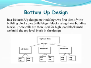
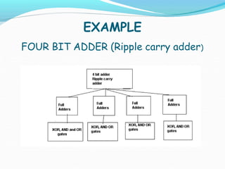
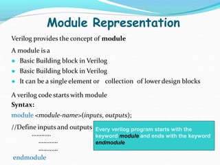
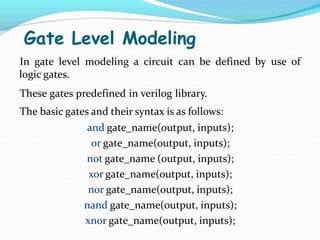
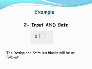
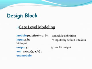
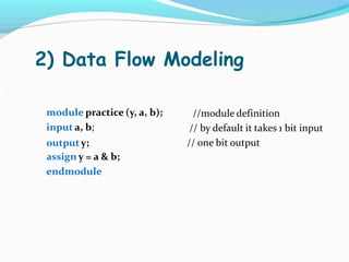
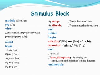
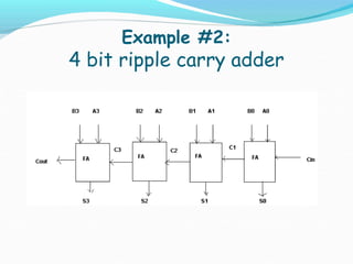
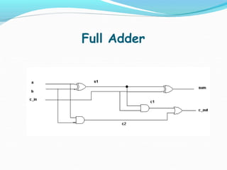
This document provides an overview of hardware description languages (HDLs) like Verilog and VHDL. It discusses that HDLs allow designing and simulating digital hardware at different levels of abstraction before fabrication. It then focuses on Verilog, describing that it is commonly used in the US while VHDL is more common in Europe. Key concepts covered include Verilog modules, simulation, levels of abstraction like gate-level and data flow modeling. Examples provided include a 2-input AND gate and a 4-bit ripple carry adder.


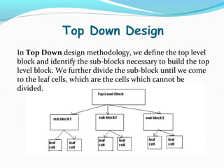
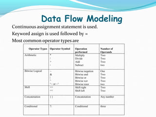
![Input Output Definition
● Once the module is defined at the start the inputs and
outputs are to be defined explicitly. e.g.
//means there are 2 inputs of one bit
● input a , b
each
● If input or output is more than 1 bit i.e. two or more bits,
then the definition will be:
input [3:0] A, B; //4 bit inputs A3-A0 and B3-B0
output [3:0] C;](https://image.slidesharecdn.com/saigoud1-240109132932-87882b08/85/vlsi-design-using-verilog-presentaion-1-13-320.jpg)

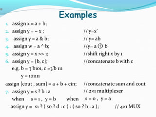
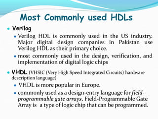
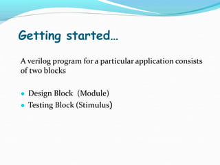
![TOP LEVEL MODULE
//Define a 4 bit 4 adder
module toplevel_fa(sum,c_out,a,b,c_in);
//I/O port declaration
output [3:0] sum;
output c_out;
input [3:0] a, b;
input c_in;
//internal nets
wire c1,c2,c3;
//Instantiate four 1-bit full adder
fulladder fa0(sum[0],c1,a[0],b[0],c_in);
fulladder fa1(sum[1],c2,a[1],b[1],c1);
fulladder fa2(sum[2],c3,a[2],b[2],c2);
fulladder fa3(sum[3],c_out,a[3],b[3],c3);
endmodule](https://image.slidesharecdn.com/saigoud1-240109132932-87882b08/85/vlsi-design-using-verilog-presentaion-1-27-320.jpg)
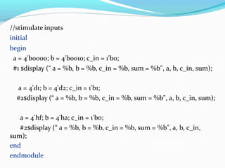
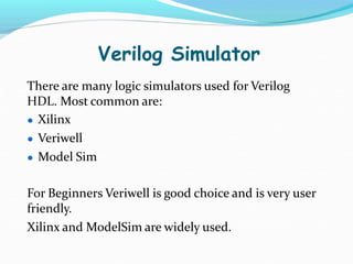
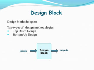
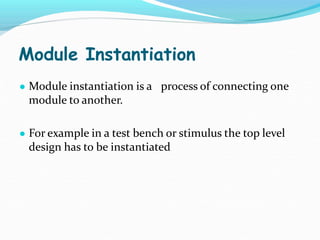
![Test Bench (stimulus)
//define stimulus toplevel module
module stimulus;
//set up variables
reg [3:0]a,b;
reg c_in;
wire [3:0] sum;
wire c_out;
//Instantiate the toplevelmodule(ripple carry adder) call it tl
toplevel_fa tl(sum,c_out,a,b,c_in);](https://image.slidesharecdn.com/saigoud1-240109132932-87882b08/85/vlsi-design-using-verilog-presentaion-1-28-320.jpg)