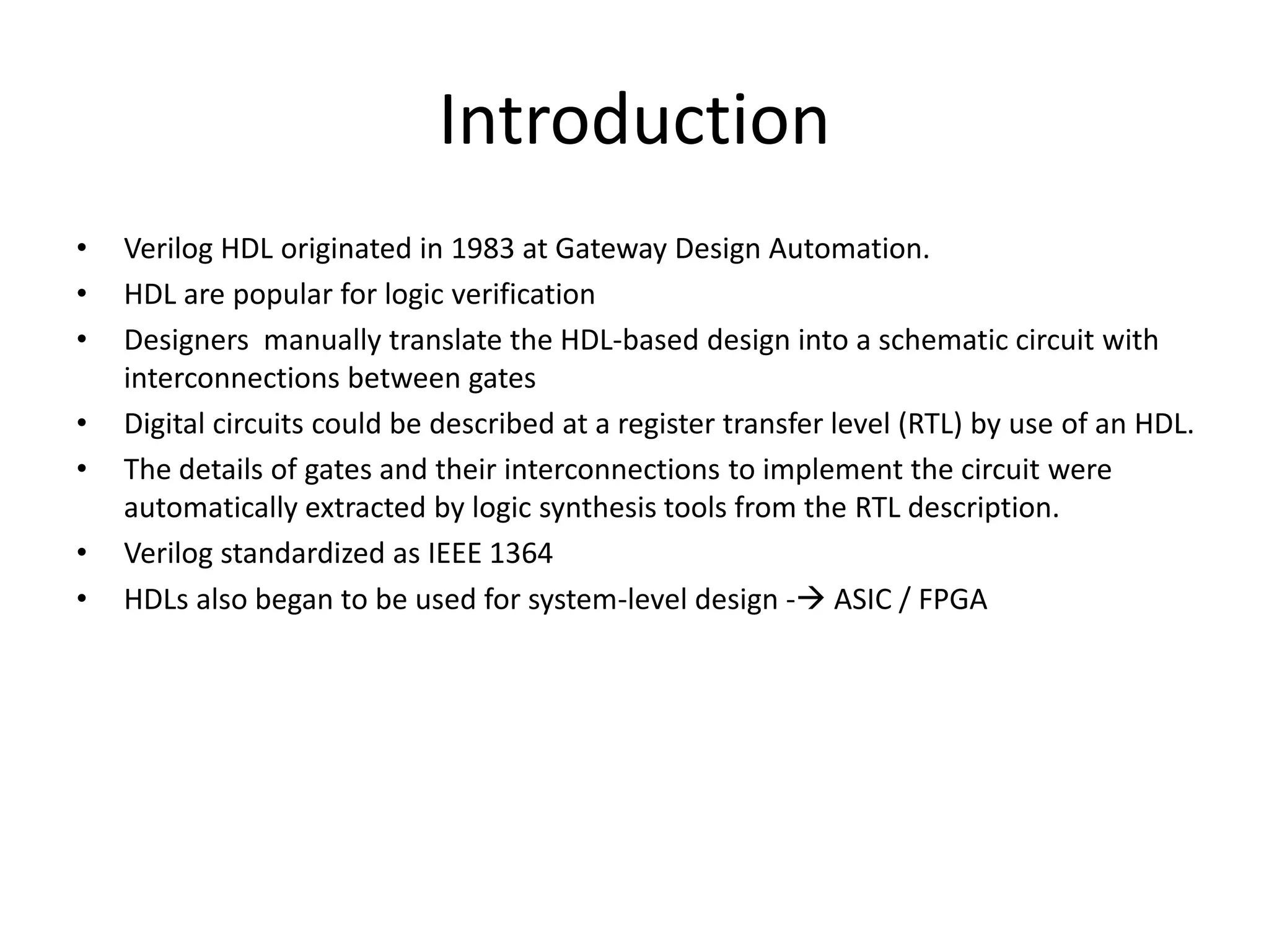
Verilog is a hardware description language (HDL) used to model electronic systems. Some key points:
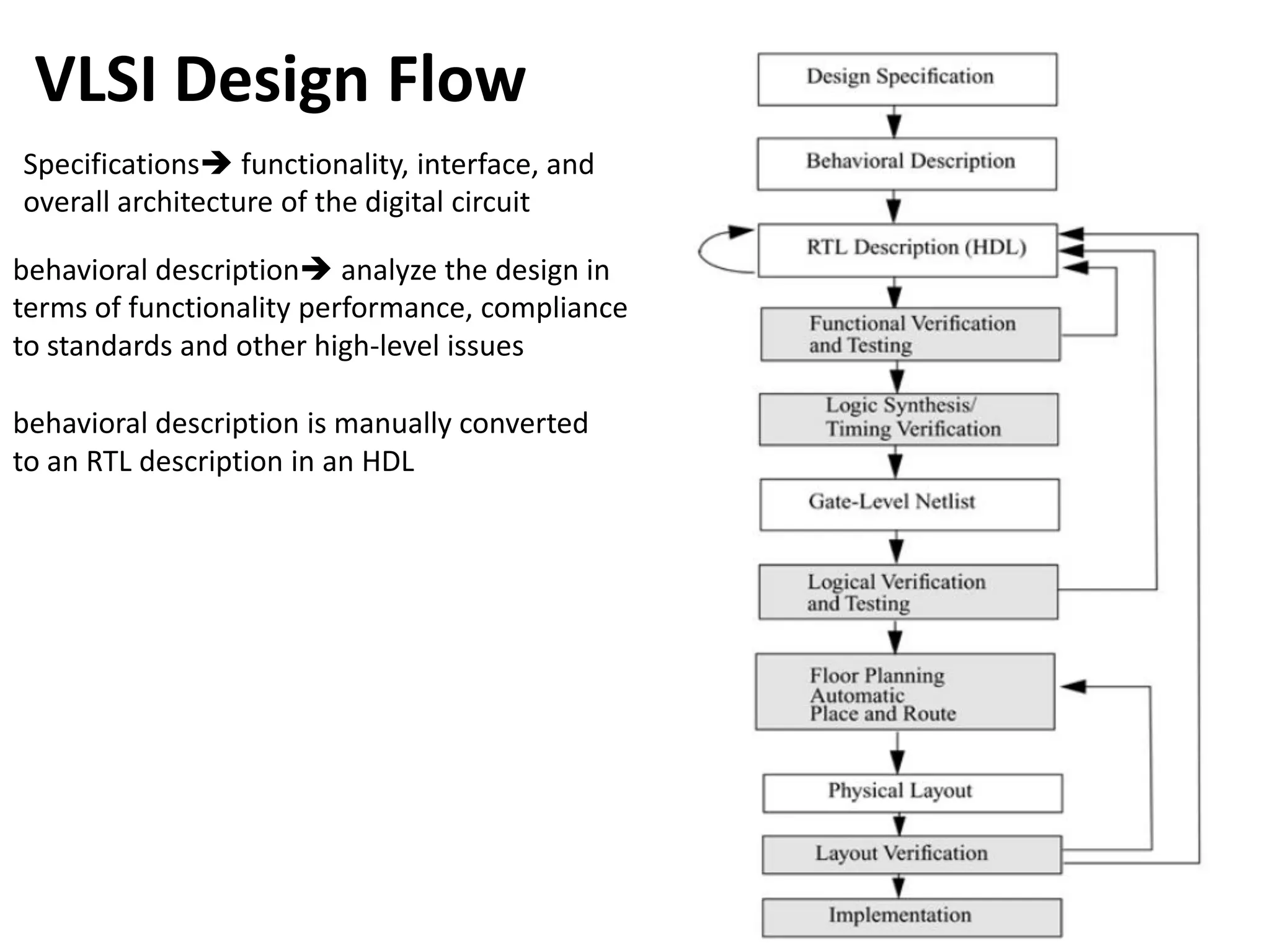
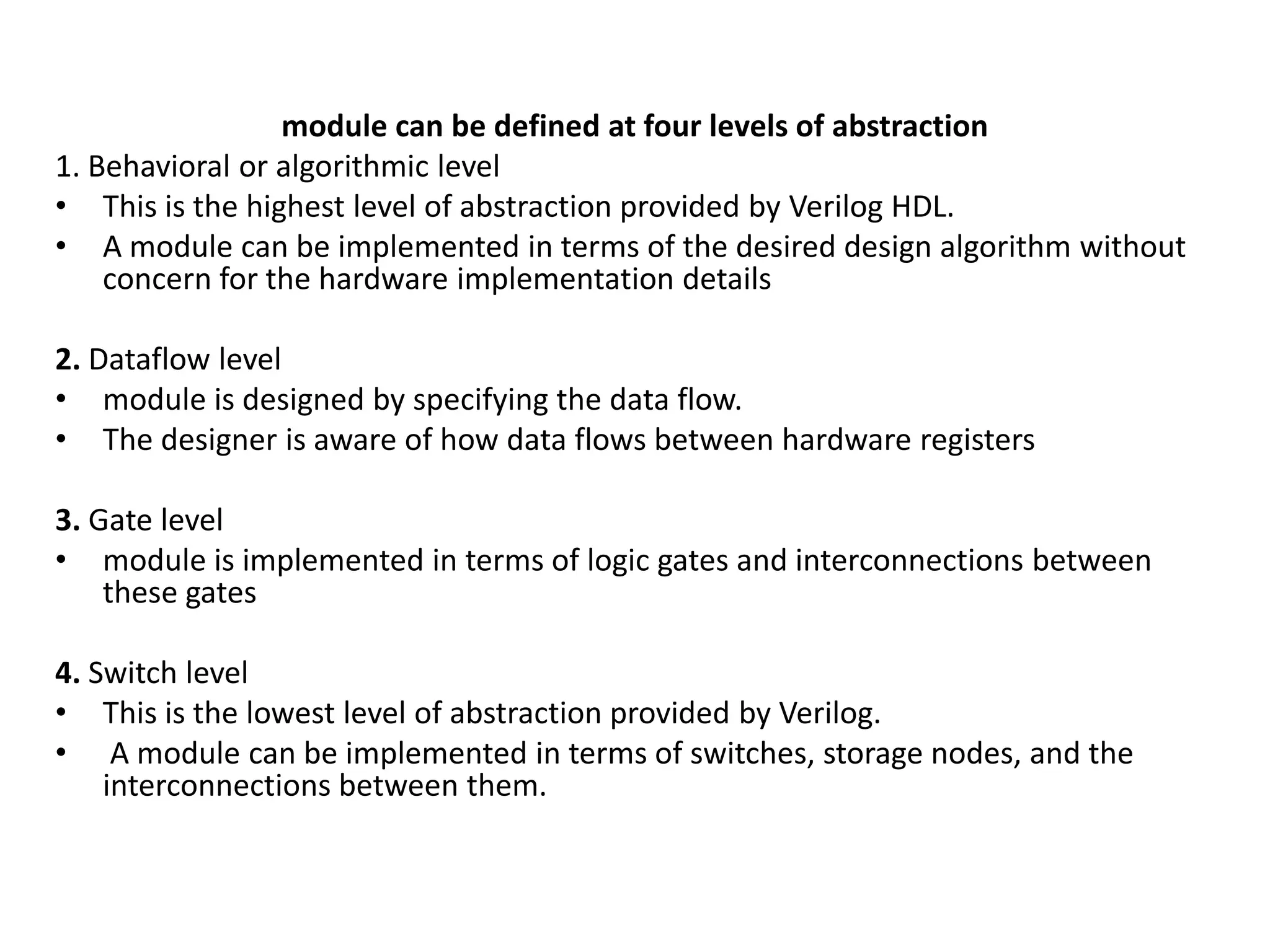
- Verilog originated in 1983 and was standardized as IEEE 1364. It is used to model digital circuits at different levels of abstraction from algorithmic to switch levels.
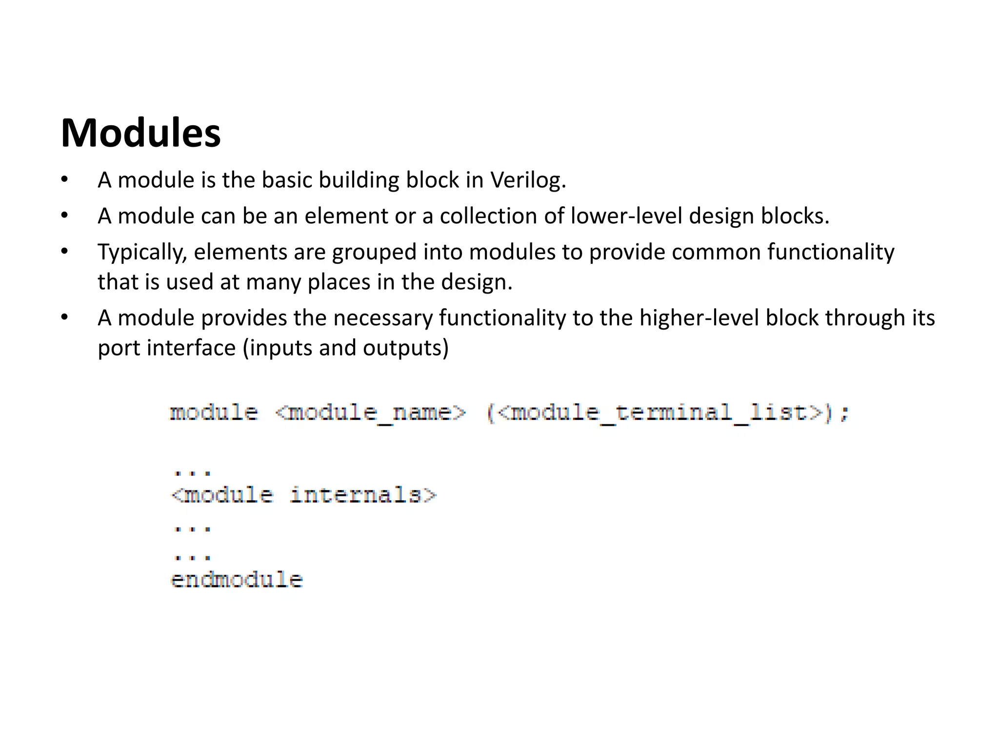
- Modules are the basic building blocks in Verilog. Designs are constructed in a hierarchical manner using instances of modules.
- Common constructs in Verilog include nets, registers, parameters, tasks, always and initial blocks, and data types like wire and reg.
- Basic gates and larger components like decoders, multiplexers, and adders can be modeled at the gate level in Verilog. Different adder architectures like


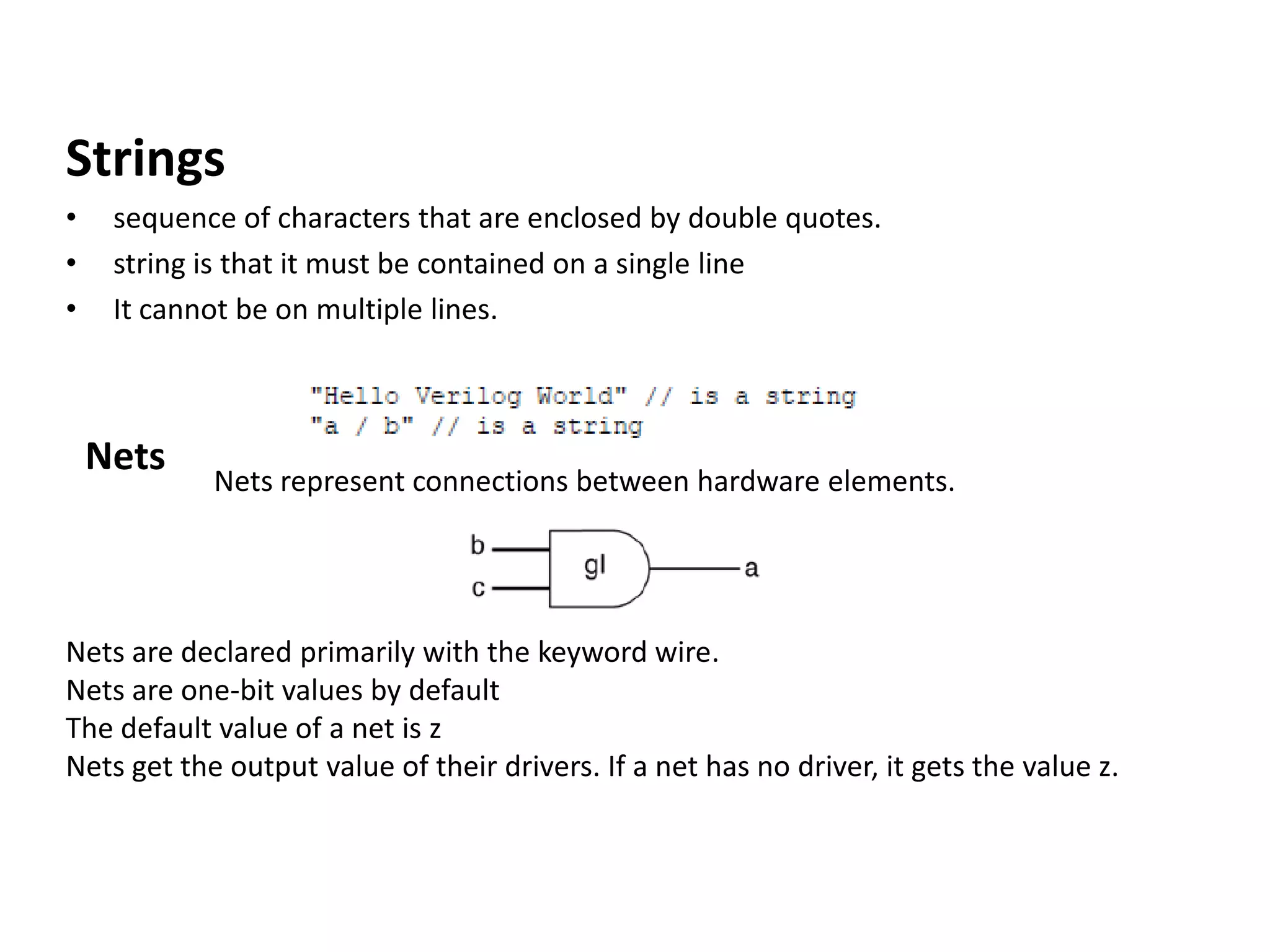
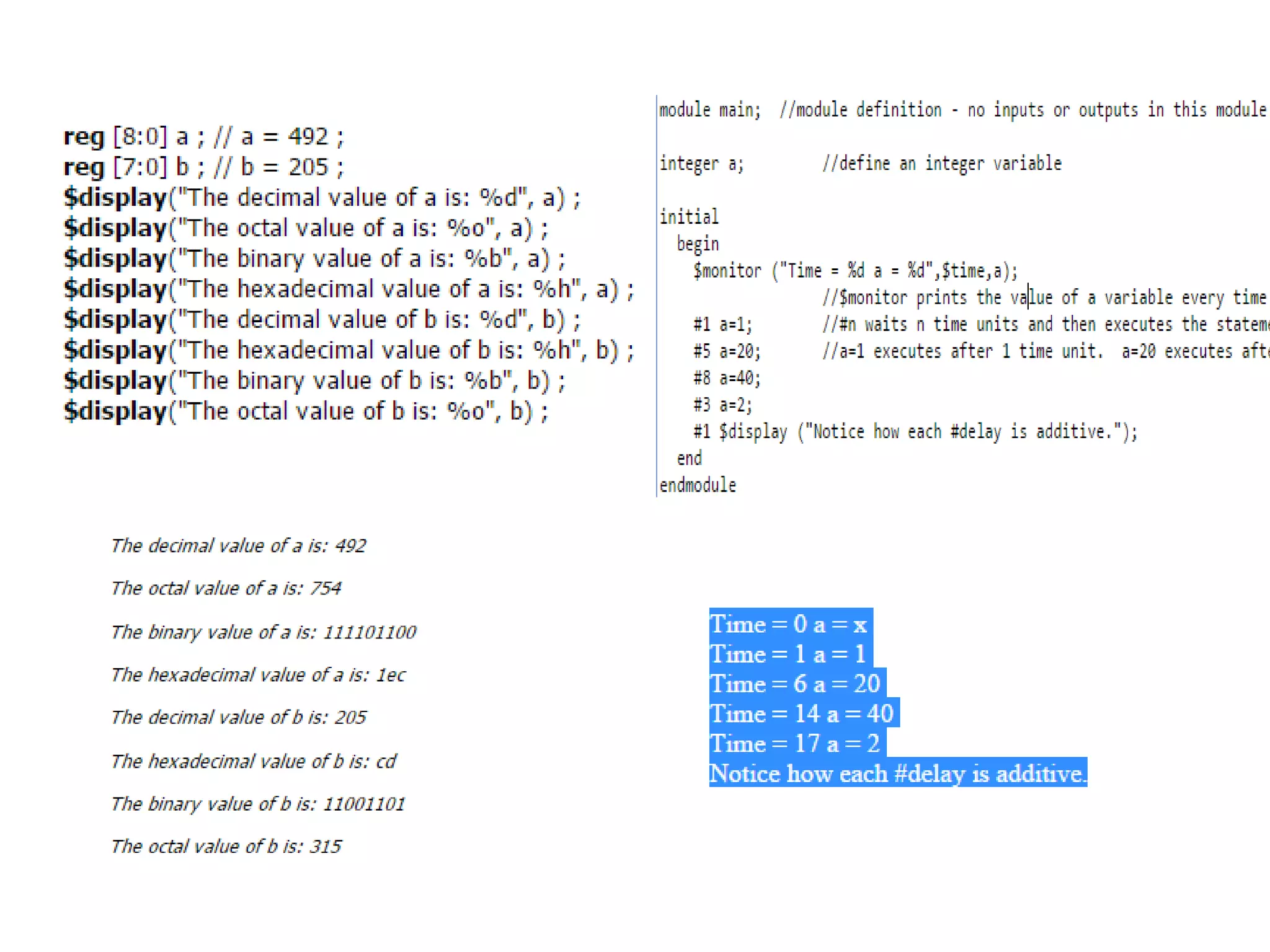
![Registers
• Registers represent data storage elements.
• Registers retain value until another value is placed onto them.
reg variable that can hold a value.
• default value for a reg data type is x
Vectors
Nets or reg data types can be declared as vectors (multiple bit widths).
If bit width is not specified, the default is scalar (1-bit).
[high# : low#] or [low# : high#]
left number in the squared brackets is always the MSB of the vector](https://image.slidesharecdn.com/verilog-190831005401/75/Verilog-12-2048.jpg)
![Vector Part Select
Arrays array is a collection of variables
Arrays are accessed by <array_name>[<subscript>]](https://image.slidesharecdn.com/verilog-190831005401/75/Verilog-13-2048.jpg)


![module stimulus;
reg clk;
reg reset;
wire[3:0] q;
ripple_carry_counter r1(q, clk, reset);
initial
clk = 1'b0;
always
#5 clk = ~clk;
initial
begin
reset = 1'b1;
#15 reset = 1'b0;
#180 reset = 1'b1;
#10 reset = 1'b0;
#20 $finish;
End
initial
$monitor($time, " Output q = %d", q);
endmodule](https://image.slidesharecdn.com/verilog-190831005401/75/Verilog-20-2048.jpg)


![2:4 Decoder
module dec24_str(
output [3:0] y,
input [1:0] a,
input en);
and (y[0], ~a[1], ~a[0], en);
and (y[1], ~a[1], a[0], en);
and (y[2], a[1], ~a[0], en);
and (y[3], a[1], a[0], en);
endmodule
module dec2_4 (a,b,en,y0,y1,y2,y3)
input a, b, en;
output y0,y1,y2,y3;
assign y0= (~a) & (~b) & en;
assign y1= (~a) & b & en;
assign y2= a & (~ b) & en;
assign y3= a & b & en;
end module](https://image.slidesharecdn.com/verilog-190831005401/75/Verilog-27-2048.jpg)
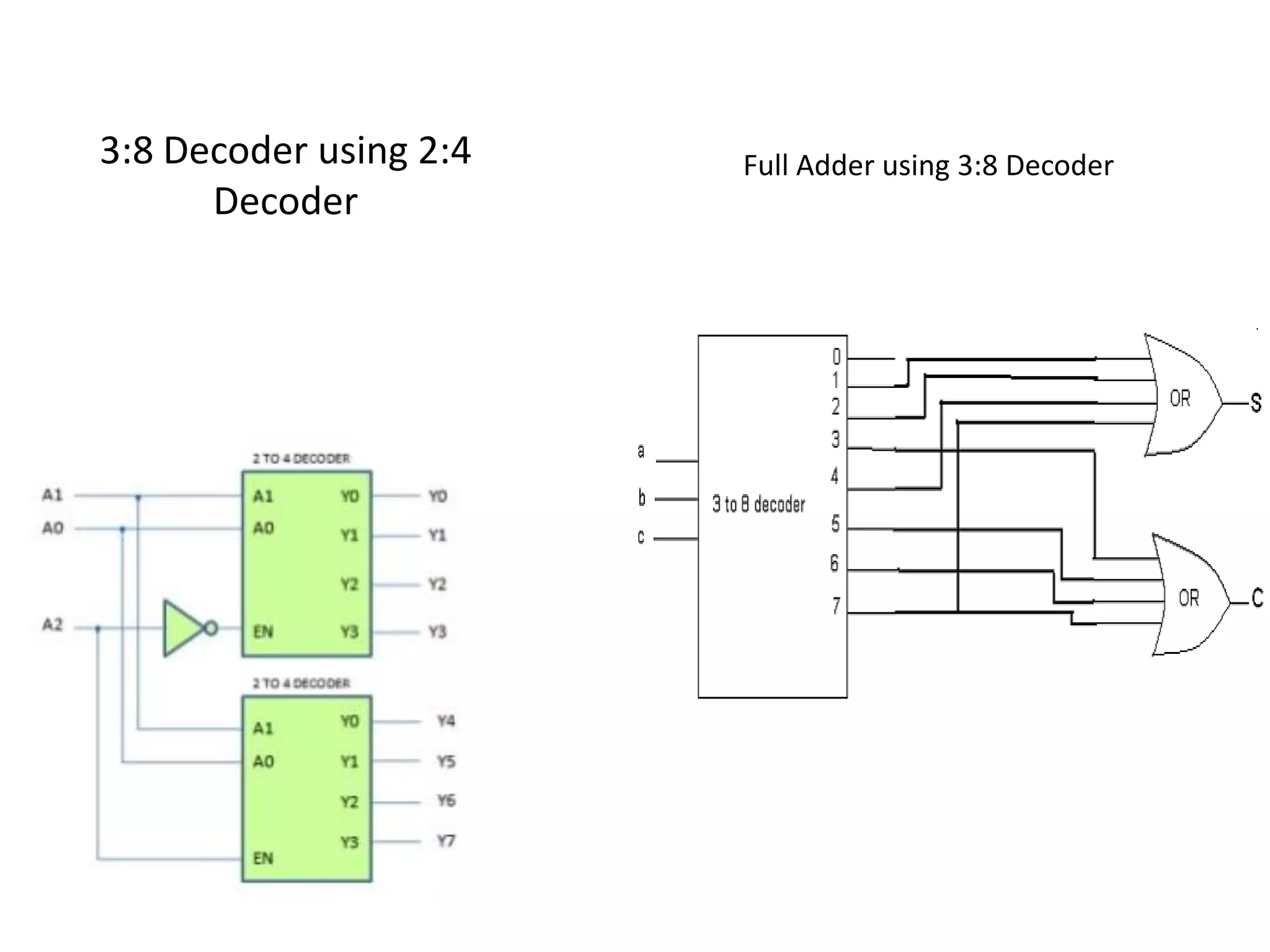
![4:16 Decoder using 2:4 Decoder
module dec4x16_str(a,en,y);
output [15:0] y,
input [3:0] a,
input en;
wire [3:0] w;
dec2x4_str u0(w, a[3:2], en);
dec2x4_str u1(y[3:0], a[1:0], w[0]);
dec2x4_str u2(y[7:4], a[1:0], w[1]);
dec2x4_str u3(y[11:8], a[1:0], w[2]);
dec2x4_str u4(y[15:12], a[1:0], w[3]);
endmodule](https://image.slidesharecdn.com/verilog-190831005401/75/Verilog-29-2048.jpg)
![4 bit Ripple Carry Adder
module four_bit_adder(x,y,cin,sum,cout);
input [3:0] x,y;
input cin;
output[3:0] sum;
output cout;
wire c1,c2,c3;
full_adder fa1(x[0],y[0],cin,sum[0],c1);
full_adder fa2(x[1],y[1],c1,sum[1],c2);
full_adder fa3(x[2],y[2],c2,sum[2],c3);
full_adder fa4(x[3],y[3],c3,sum[3],cout);
endmodule](https://image.slidesharecdn.com/verilog-190831005401/75/Verilog-30-2048.jpg)


![Carry Save Adder module fulladder( a,b,cin,sum,carry);
input a,b,cin;
output sum,carry;
assign sum = a ^ b ^ cin;
assign carry = (a & b) | (cin & b) | (a & cin);
endmodule
module CSA ( x,y,z,s,cout);
input [3:0] x,y,z;
output [4:0] s;
output cout;
wire [3:0] c1,s1,c2;
fulladder fa_inst10(x[0],y[0],z[0],s1[0],c1[0]);
fulladder fa_inst11(x[1],y[1],z[1],s1[1],c1[1]);
fulladder fa_inst12(x[2],y[2],z[2],s1[2],c1[2]);
fulladder fa_inst13(x[3],y[3],z[3],s1[3],c1[3]);
fulladder fa_inst20(s1[1],c1[0],1'b0,s[1],c2[1]);
fulladder fa_inst21(s1[2],c1[1],c2[1],s[2],c2[2]);
fulladder fa_inst22(s1[3],c1[2],c2[2],s[3],c2[3]);
fulladder fa_inst23(1'b0,c1[3],c2[3],s[4],cout);
assign s[0] = s1[0];
endmodule](https://image.slidesharecdn.com/verilog-190831005401/75/Verilog-33-2048.jpg)


![電路學 - [第六章] 二階RLC電路](https://cdn.slidesharecdn.com/ss_thumbnails/circuitch6-150613063009-lva1-app6892-thumbnail.jpg?width=640&height=640&fit=bounds)