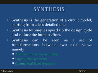
The document outlines techniques for synthesis and optimization in digital circuit design, focusing on both basic and advanced methods. It covers the importance of optimization for combinational and sequential circuits, explaining various scheduling algorithms and the relevant concepts of hardware modeling. Furthermore, it discusses the relationship between design space, area, and performance, emphasizing the role of optimization in achieving competitive circuit designs.
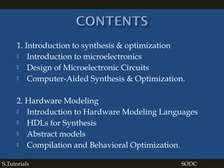
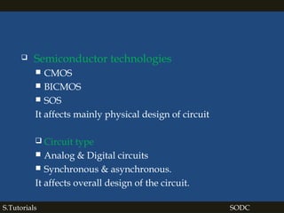

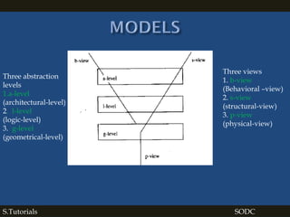
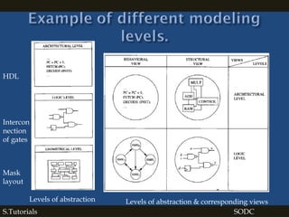
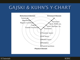

![S.Tutorials SODC
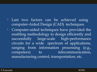
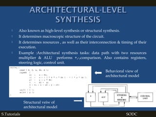
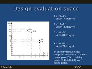
Taking 1 multiplier,1 ALU a1=1,a2=1
a1-multiplier,a2-ALU
Area required is
5 units of area for 1 multiplier
1 units of area for 1 ALU
1 units of area for Controlunit,steering,memory.
Total area = 5+1+1=7 units
Multiplier
Latency required is
1 cycle= 3* x , x+dx = * , +
2 cycle=3*x*u, x1<a = * , <
3cycle=3*x*u*dx = *
4cycle=3*y , u-(3*x*u*dx)= * , -
5cycle=3*y* dx = *
6cycle=u* dx, [u-(3*x*u* dx) -3*y* dx]
= * , -
7cycle=y+u*dx = +
Total 7 cycles to execute](https://image.slidesharecdn.com/synthesisoptimizationofdigitalcircuits-180130165118/85/Synthesis-optimization-of-digital-circuits-24-320.jpg)
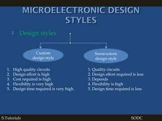
![S.Tutorials SODC
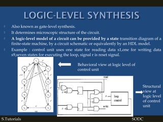
Taking 2 multipliers , 2 ALUs
a1=2 , a2=2
Area required is
5 units of area for 1 multiplier= 2*5 =10 units
1 units of area for 1 ALU= 2*1= 2 units
1 units of area for Control unit, steering,memory.
Total area = 10+2+1=13 units
multiplier
multiplier
Latency required is
1 cycle= 3* x , u*dx,3*y, x+dx
= * , +,*
2 cycle=3*x*u*dx, x1<a , 3*y* dx,
y+u*dx = * , <,*,+
3cycle=u-(3*x*u*dx) = -
4cycle= [u-(3*x*u* dx) -3*y* dx]
= -
Total 4 cycles to execute](https://image.slidesharecdn.com/synthesisoptimizationofdigitalcircuits-180130165118/85/Synthesis-optimization-of-digital-circuits-25-320.jpg)
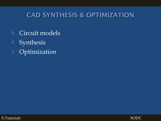
![S.Tutorials SODC
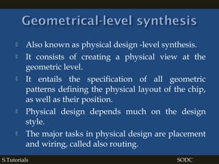
Taking 2 multipliers , 1 ALUs
a1=2 , a2=1
Area required is
5 units of area for 1 multiplier= 2*5 =10
units
1 units of area for 1 ALU= 1= 1 units
1 units of area for Control unit,
steering,memory.
Total area = 10+1+1=12 units
Latency required is
1 cycle= 3* x , u*dx,3*y, x+dx
= * , +,*
2 cycle=3*x*u*dx, 3*y* dx,
y+u*dx = * , *,+
3cycle=u-(3*x*u*dx) = -
4cycle= [u-(3*x*u* dx) -3*y* dx] = -
5cycle=x1<a= <
Total 5 cycles to execute](https://image.slidesharecdn.com/synthesisoptimizationofdigitalcircuits-180130165118/85/Synthesis-optimization-of-digital-circuits-26-320.jpg)
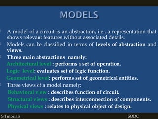
![S.Tutorials SODC
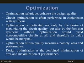
Taking 1 multiplier,1 ALU a1=1,a2=2
a1-multiplier,a2-ALU
Area required is
5 units of area for 1 multiplier
1 units of area for 1 ALU=2*1=2
1 units of area for Control
unit,steering,memory.
Total area = 5+2+1=8 units
Latency required is
1 cycle= 3* x , x+dx = * , +
2 cycle=3*x*u, x1<a = * , <
3cycle=3*x*u*dx = *
4cycle=3*y , u-(3*x*u*dx)= * , -
5cycle=3*y* dx = *
6cycle=u* dx, [u-(3*x*u* dx) -3*y* dx]
= * , -
7cycle=y+u*dx = +
Total 7 cycles to execute](https://image.slidesharecdn.com/synthesisoptimizationofdigitalcircuits-180130165118/85/Synthesis-optimization-of-digital-circuits-27-320.jpg)
![SODC[As per VTU M.Tech IV Sem]
For notes & slides contact to:
s.tutorials04@gmail.com
S.Tutorials SODC](https://image.slidesharecdn.com/synthesisoptimizationofdigitalcircuits-180130165118/85/Synthesis-optimization-of-digital-circuits-30-320.jpg)


