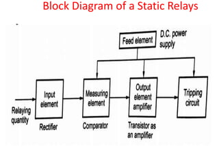
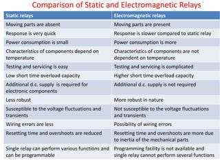
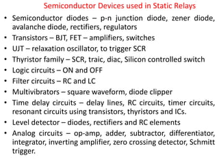
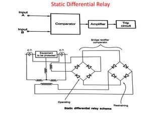
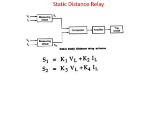
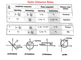
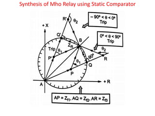
UNIT – IV
Static Relays and Numerical Protection
Unit-IV
Static relays and Numerical Protection
Static relays – Phase, Amplitude Comparators –
Synthesis of various relays using Static
comparators– Block diagram of Numerical relays –
Over current protection, transformer differential
protection, distance protection of transmission lines.
Static Relays
• The relays which do not use moving parts and use
the solid state electronic components such as
diodes, transistors etc. are called static relays.
• Static relay response circuit does not have moving
parts and made up of electronic components but
its tripping circuit may be electronic or
electromagnetic.
Block Diagram of a Static Relays
Comparison of Static and Electromagnetic Relays
Static relays Electromagnetic relays
Moving parts are absent Moving parts are present
Response is very quick Response is slower compared to static relay
Power consumption is small Power consumption is more
Characteristics of components depend on
temperature
Characteristics of components are not
dependent on temperature
Testing and servicing is easy Testing and servicing is complicated
Low short time overload capacity Higher short time overload capacity
Additional d.c. supply is required for
electronic components
Additional d.c. supply is not required
Less robust More robust in nature
Susceptible to the voltage fluctuations and
transients
Not susceptible to the voltage fluctuations
and transients
Wiring errors are less Possibility of wiring errors
Resetting time and overshoots are reduced Resetting time and overshoots are more due
to inertia of the mechanical parts
Single relay can perform various functions and
can be programmable
Programming facility is not available and
single relay cannot perform several functions
Advantages of Static Relays
• The moving parts are absent. The moving parts are
present only in the actual tripping circuit and not
in the control circuit.
• The burden on C.T. gets considerably reduced thus
smaller C.T.s can be used
• The power consumption is very low as most of the
circuit are electronic
• The response is very quick
• As moving parts are absent, the minimum
maintenance is required. No bearing friction or
contact troubles exist.
Advantages of Static Relays
• The resetting time can be reduced and overshoots
can be reduced due to absence of mechanical
inertia and thermal storage
• The sensitivity is high as signal amplification can be
achieved very easily
• The use of printed circuits eliminates the wiring
errors and mass production is possible
• As electronic circuits can be used to perform
number of functions, the wide range of operating
characteristics can be obtained, which almost
approach to ideal requirements
Advantages of Static Relays
• The low energy levels required in the measuring
circuits make the relays smaller and compact in
size
• The testing and servicing is simplified
• Smaller and compact in size
• No gravity effect on operation of static relays.
Hence can be used in ships, aircrafts etc.
• A single relay can perform several functions like
overcurrent, under voltage single phasing
protection by incorporating respective functional
blocks. This is not possible in electromagnetic
relays.
limitations of Static Relays
• The characteristics of electronic components such as
transistors, diodes etc. are temperature dependent.
Hence relay characteristics vary with temperature and
ageing
• The reliability is unpredictable as it depends on a large
number of small components and their electrical
connections
• These relays have low short time overload capacity
compared to electromagnetic relays
• Additional d.c. supply is required for various
transistors circuits
• Susceptible to the voltage fluctuations and transients
• Less robust compared to electromagnetic relays
Comparators
• Many relays operate based on the resultant of the
comparison of the two quantities. The comparator
is that part of relay, which receives two input and it
produces the output based on the comparison of
the two inputs.
• In some relays the amplitude of the two quantities,
entering and leaving a protected zone are
compared.
• While in some relays the phase angle between the
sending end quantities and receiving end
quantities are compared.
• Thus the phase and amplitude comparators are
necessary for the relay opeartion
Comparators
Amplitude Comparators
Rectifier Bridge Comparator
Integrating Amplitude Comparator
Phase Comparator
Sine type Phase Comparator
Cosine type Phase Comparator
Duality in Comparators
Hybrid Comparators
Semiconductor Devices used in Static Relays
• Semiconductor diodes – p-n junction diode, zener diode,
avalanche diode, rectifiers, regulators
• Transistors – BJT, FET – amplifiers, switches
• UJT – relaxation oscillator, to trigger SCR
• Thyristor family – SCR, traic, diac, Silicon controlled switch
• Logic circuits – ON and OFF
• Filter circuits – RC and LC
• Multivibrators – square waveform, diode clipper
• Time delay circuits – delay lines, RC circuits, timer circuits,
resonant circuits using transistors, thyristors and ICs.
• Level detector – diodes, rectifiers and RC elements
• Analog circuits – op-amp, adder, subtractor, differentiator,
integrator, inverting amplifier, zero crossing detector, Schmitt
trigger.
Static Over Current Relay
Static Time-Current Characteristics
Static Instantaneous Overcurrent Relay
Inverse Time-Current Relay
Directional Static Overcurrent Relay
Static Differential Relay
Static Distance Relay
Synthesis of Mho Relay using Static Comparator
Synthesis of Reactance Relay using Static Comparator
Synthesis of Impedance Relay using Static Comparator
Block Diagram of Numerical Relay
Advantages of Numerical Relay
• It uses electronic circuits for functioning and hence
is compact in size
• The numerical relay can be made multifunctional
with suitable modifications in software or with
slight modification in hardware
• It uses fewer components resulting in less inter
connections and reduced component failures.
Hence it is more reliable
• Relay characteristics are stored in memory of
microprocessor. Hence it provides better matching
of protection characteristics
Advantages of Numerical Relay
• Numerical relay can be easily interfaced with digital
communication equipments (like fibre optical
communication)
• Numerical relay imposes less burden on CTs and PTs
• It has high pick up ratio and greater sensitivity
• Tripping time of ½ cycle or less can be achieved with
the use of numerical relay
• It has least resetting time
• It can provide data history for future reference
• One unit can perform relaying of several systems
• Very economical for large power systems
• Useful for centrally co-ordinated back up protection
Limitations of Numerical Relay
• The microprocessor unit needs to be properly
shielded as gets affected by external interferences
and environment
• Proper care of earthing must be taken
• If it is multifunctional, then failure of one element
affects all the systems
• It has risk of hacking
• The relay can be faster but of no use if circuit
breaker operation is not as fast as relay.
Numerical Overcurrent Protection
Numerical Differential Protection of Transformer
Numerical Distance Protection

Solid State relays for Engineering Students

  • 1.
    UNIT – IV StaticRelays and Numerical Protection
  • 2.
    Unit-IV Static relays andNumerical Protection Static relays – Phase, Amplitude Comparators – Synthesis of various relays using Static comparators– Block diagram of Numerical relays – Over current protection, transformer differential protection, distance protection of transmission lines.
  • 3.
    Static Relays • Therelays which do not use moving parts and use the solid state electronic components such as diodes, transistors etc. are called static relays. • Static relay response circuit does not have moving parts and made up of electronic components but its tripping circuit may be electronic or electromagnetic.
  • 4.
    Block Diagram ofa Static Relays
  • 5.
    Comparison of Staticand Electromagnetic Relays Static relays Electromagnetic relays Moving parts are absent Moving parts are present Response is very quick Response is slower compared to static relay Power consumption is small Power consumption is more Characteristics of components depend on temperature Characteristics of components are not dependent on temperature Testing and servicing is easy Testing and servicing is complicated Low short time overload capacity Higher short time overload capacity Additional d.c. supply is required for electronic components Additional d.c. supply is not required Less robust More robust in nature Susceptible to the voltage fluctuations and transients Not susceptible to the voltage fluctuations and transients Wiring errors are less Possibility of wiring errors Resetting time and overshoots are reduced Resetting time and overshoots are more due to inertia of the mechanical parts Single relay can perform various functions and can be programmable Programming facility is not available and single relay cannot perform several functions
  • 6.
    Advantages of StaticRelays • The moving parts are absent. The moving parts are present only in the actual tripping circuit and not in the control circuit. • The burden on C.T. gets considerably reduced thus smaller C.T.s can be used • The power consumption is very low as most of the circuit are electronic • The response is very quick • As moving parts are absent, the minimum maintenance is required. No bearing friction or contact troubles exist.
  • 7.
    Advantages of StaticRelays • The resetting time can be reduced and overshoots can be reduced due to absence of mechanical inertia and thermal storage • The sensitivity is high as signal amplification can be achieved very easily • The use of printed circuits eliminates the wiring errors and mass production is possible • As electronic circuits can be used to perform number of functions, the wide range of operating characteristics can be obtained, which almost approach to ideal requirements
  • 8.
    Advantages of StaticRelays • The low energy levels required in the measuring circuits make the relays smaller and compact in size • The testing and servicing is simplified • Smaller and compact in size • No gravity effect on operation of static relays. Hence can be used in ships, aircrafts etc. • A single relay can perform several functions like overcurrent, under voltage single phasing protection by incorporating respective functional blocks. This is not possible in electromagnetic relays.
  • 9.
    limitations of StaticRelays • The characteristics of electronic components such as transistors, diodes etc. are temperature dependent. Hence relay characteristics vary with temperature and ageing • The reliability is unpredictable as it depends on a large number of small components and their electrical connections • These relays have low short time overload capacity compared to electromagnetic relays • Additional d.c. supply is required for various transistors circuits • Susceptible to the voltage fluctuations and transients • Less robust compared to electromagnetic relays
  • 10.
    Comparators • Many relaysoperate based on the resultant of the comparison of the two quantities. The comparator is that part of relay, which receives two input and it produces the output based on the comparison of the two inputs. • In some relays the amplitude of the two quantities, entering and leaving a protected zone are compared. • While in some relays the phase angle between the sending end quantities and receiving end quantities are compared. • Thus the phase and amplitude comparators are necessary for the relay opeartion
  • 11.
  • 12.
  • 13.
  • 14.
  • 15.
  • 16.
  • 17.
    Sine type PhaseComparator
  • 18.
  • 19.
  • 20.
  • 21.
  • 22.
    Semiconductor Devices usedin Static Relays • Semiconductor diodes – p-n junction diode, zener diode, avalanche diode, rectifiers, regulators • Transistors – BJT, FET – amplifiers, switches • UJT – relaxation oscillator, to trigger SCR • Thyristor family – SCR, traic, diac, Silicon controlled switch • Logic circuits – ON and OFF • Filter circuits – RC and LC • Multivibrators – square waveform, diode clipper • Time delay circuits – delay lines, RC circuits, timer circuits, resonant circuits using transistors, thyristors and ICs. • Level detector – diodes, rectifiers and RC elements • Analog circuits – op-amp, adder, subtractor, differentiator, integrator, inverting amplifier, zero crossing detector, Schmitt trigger.
  • 23.
  • 24.
  • 25.
  • 26.
  • 27.
  • 28.
  • 29.
  • 30.
  • 31.
  • 32.
    Synthesis of MhoRelay using Static Comparator
  • 33.
    Synthesis of MhoRelay using Static Comparator
  • 34.
    Synthesis of ReactanceRelay using Static Comparator
  • 35.
    Synthesis of ReactanceRelay using Static Comparator
  • 36.
    Synthesis of ReactanceRelay using Static Comparator
  • 37.
    Synthesis of ImpedanceRelay using Static Comparator
  • 38.
    Block Diagram ofNumerical Relay
  • 39.
    Advantages of NumericalRelay • It uses electronic circuits for functioning and hence is compact in size • The numerical relay can be made multifunctional with suitable modifications in software or with slight modification in hardware • It uses fewer components resulting in less inter connections and reduced component failures. Hence it is more reliable • Relay characteristics are stored in memory of microprocessor. Hence it provides better matching of protection characteristics
  • 40.
    Advantages of NumericalRelay • Numerical relay can be easily interfaced with digital communication equipments (like fibre optical communication) • Numerical relay imposes less burden on CTs and PTs • It has high pick up ratio and greater sensitivity • Tripping time of ½ cycle or less can be achieved with the use of numerical relay • It has least resetting time • It can provide data history for future reference • One unit can perform relaying of several systems • Very economical for large power systems • Useful for centrally co-ordinated back up protection
  • 41.
    Limitations of NumericalRelay • The microprocessor unit needs to be properly shielded as gets affected by external interferences and environment • Proper care of earthing must be taken • If it is multifunctional, then failure of one element affects all the systems • It has risk of hacking • The relay can be faster but of no use if circuit breaker operation is not as fast as relay.
  • 42.
  • 43.
  • 44.
  • 45.