Download as PPSX, PPTX

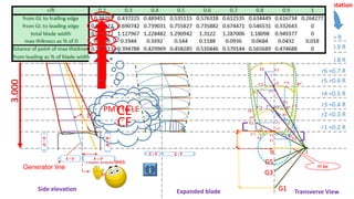
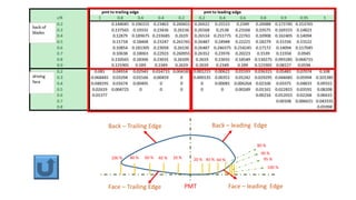


This document provides instructions for drawing a propeller using the Holst method. It includes diagrams showing: - The radii of 9 sections of the propeller blades as a percentage of the total radius R. - Diagrams labeling elements of the propeller including the generator line, directrix, tip and root thickness, rake, and leading and trailing edges. - A side view showing the expanded blade outline and transverse view. - Labels for elements in a developed blade outline including the line of maximum thickness and projected outlines.


