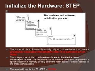
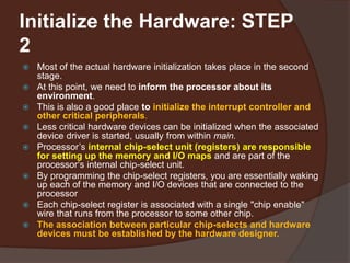
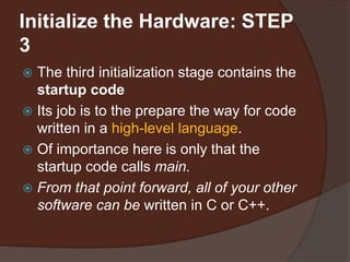
UNIT II
Get to Know the
Processor
 If you'll be doing any assembly language
programming, you will need to
familiarize yourself with the processor's
architecture and basic instruction
set.
 Everything you need to know about the
processor can be found in the
databooks (Manuals).
Processors in General
 Many of the most common processors are
members of families of related devices
 The most obvious example is Intel's 80x86
family, which spans from the original 8086 to the
Pentium II-and beyond.
 In fact, the 80x86 family has been so successful
that it has spawned an entire industry of
imitators.
 The term processor refers to any of three types
of devices known as
 microprocessors,
 microcontrollers, and
 digital signal processors
Intel's 80188EB Processor
 The processor on the Arcom board is an Intel 80188EB-a
microcontroller version of the 80186.
 In addition to the CPU, the 80188EB contains an interrupt control
unit, two programmable I/O ports, three timer/counters, two serial
ports, a DRAM controller, and a chip-select unit.
 These extra hardware devices are located within the same chip and
are referred to as on-chip peripherals.
 The CPU is able to communicate with and control the on-chip
peripherals directly, via internal buses.
 Although the on-chip peripherals are distinct hardware devices, they
act like little extensions of the 80186 CPU.
 The software can control them by reading and writing a 256-byte block
of registers known as the peripheral control block (PCB).
 The control and status registers for each of the on-chip peripherals are
located at fixed offsets from the PCB base address.
 The exact offset of each register can be found in a table in the
80188EB Microprocessor User's Manual.
Intel's 80188EB Processor:
Databook
 Other things you'll want to learn about the
processor from its databook are:
 Where should the interrupt vector table be located?
Does it have to be located at a specific address in
memory? If not, how does the processor know where to
find it?
 What is the format of the interrupt vector table? Is it
just a table of pointers to ISR functions?
 Are there any special interrupts, sometimes called traps,
that are generated within the processor itself? Must an ISR
be written to handle each of these?
 How are interrupts enabled and disabled (globally and
individually)?
 How are interrupts acknowledged or cleared?
Initialize the Hardware
 The final step in getting to know your new hardware
is to write some initialization software
 During hardware initialization it will be impossible to
avoid using assembly language.
 All processor-based boards require some amount of
software testing to confirm the correctness of the
hardware design and the proper functioning of the
various peripherals.
 The hardware initialization should be executed
before the startup code
 The code described there assumes that the
hardware has already been initialized and concerns
itself only with creating a proper runtime
environment for high-level language programs
Initialize the Hardware: STEP
1
 The first stage of the initialization process is the reset code.
 This is a small piece of assembly (usually only two or three instructions) that the
processor executes immediately after it is powered on or
reset.
 The sole purpose of this code is to transfer control to the hardware
initialization routine. The first instruction of the reset code must be placed at a
specific location in memory, usually called the reset address, that is specified in
the processor databook.
 The reset address for the 80188EB is FFFF0h.
The hardware and software
initialization process
Initialize the Hardware: STEP
2
 Most of the actual hardware initialization takes place in the second
stage.
 At this point, we need to inform the processor about its
environment.
 This is also a good place to initialize the interrupt controller and
other critical peripherals.
 Less critical hardware devices can be initialized when the associated
device driver is started, usually from within main.
 Processor’s internal chip-select unit (registers) are responsible
for setting up the memory and I/O maps and are part of the
processor‘s internal chip-select unit.
 By programming the chip-select registers, you are essentially waking
up each of the memory and I/O devices that are connected to the
processor
 Each chip-select register is associated with a single "chip enable"
wire that runs from the processor to some other chip.
 The association between particular chip-selects and hardware
devices must be established by the hardware designer.
Initialize the Hardware: STEP
3
 The third initialization stage contains the
startup code
 Its job is to the prepare the way for code
written in a high-level language.
 Of importance here is only that the
startup code calls main.
 From that point forward, all of your other
software can be written in C or C++.

SYBSC IT SEM IV EMBEDDED SYSTEMS UNIT II Processor Family

  • 1.
  • 2.
    Get to Knowthe Processor  If you'll be doing any assembly language programming, you will need to familiarize yourself with the processor's architecture and basic instruction set.  Everything you need to know about the processor can be found in the databooks (Manuals).
  • 3.
    Processors in General Many of the most common processors are members of families of related devices  The most obvious example is Intel's 80x86 family, which spans from the original 8086 to the Pentium II-and beyond.  In fact, the 80x86 family has been so successful that it has spawned an entire industry of imitators.  The term processor refers to any of three types of devices known as  microprocessors,  microcontrollers, and  digital signal processors
  • 4.
    Intel's 80188EB Processor The processor on the Arcom board is an Intel 80188EB-a microcontroller version of the 80186.  In addition to the CPU, the 80188EB contains an interrupt control unit, two programmable I/O ports, three timer/counters, two serial ports, a DRAM controller, and a chip-select unit.  These extra hardware devices are located within the same chip and are referred to as on-chip peripherals.  The CPU is able to communicate with and control the on-chip peripherals directly, via internal buses.  Although the on-chip peripherals are distinct hardware devices, they act like little extensions of the 80186 CPU.  The software can control them by reading and writing a 256-byte block of registers known as the peripheral control block (PCB).  The control and status registers for each of the on-chip peripherals are located at fixed offsets from the PCB base address.  The exact offset of each register can be found in a table in the 80188EB Microprocessor User's Manual.
  • 5.
    Intel's 80188EB Processor: Databook Other things you'll want to learn about the processor from its databook are:  Where should the interrupt vector table be located? Does it have to be located at a specific address in memory? If not, how does the processor know where to find it?  What is the format of the interrupt vector table? Is it just a table of pointers to ISR functions?  Are there any special interrupts, sometimes called traps, that are generated within the processor itself? Must an ISR be written to handle each of these?  How are interrupts enabled and disabled (globally and individually)?  How are interrupts acknowledged or cleared?
  • 6.
    Initialize the Hardware The final step in getting to know your new hardware is to write some initialization software  During hardware initialization it will be impossible to avoid using assembly language.  All processor-based boards require some amount of software testing to confirm the correctness of the hardware design and the proper functioning of the various peripherals.  The hardware initialization should be executed before the startup code  The code described there assumes that the hardware has already been initialized and concerns itself only with creating a proper runtime environment for high-level language programs
  • 7.
    Initialize the Hardware:STEP 1  The first stage of the initialization process is the reset code.  This is a small piece of assembly (usually only two or three instructions) that the processor executes immediately after it is powered on or reset.  The sole purpose of this code is to transfer control to the hardware initialization routine. The first instruction of the reset code must be placed at a specific location in memory, usually called the reset address, that is specified in the processor databook.  The reset address for the 80188EB is FFFF0h. The hardware and software initialization process
  • 8.
    Initialize the Hardware:STEP 2  Most of the actual hardware initialization takes place in the second stage.  At this point, we need to inform the processor about its environment.  This is also a good place to initialize the interrupt controller and other critical peripherals.  Less critical hardware devices can be initialized when the associated device driver is started, usually from within main.  Processor’s internal chip-select unit (registers) are responsible for setting up the memory and I/O maps and are part of the processor‘s internal chip-select unit.  By programming the chip-select registers, you are essentially waking up each of the memory and I/O devices that are connected to the processor  Each chip-select register is associated with a single "chip enable" wire that runs from the processor to some other chip.  The association between particular chip-selects and hardware devices must be established by the hardware designer.
  • 9.
    Initialize the Hardware:STEP 3  The third initialization stage contains the startup code  Its job is to the prepare the way for code written in a high-level language.  Of importance here is only that the startup code calls main.  From that point forward, all of your other software can be written in C or C++.