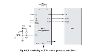
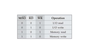
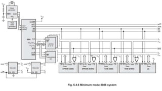
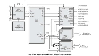
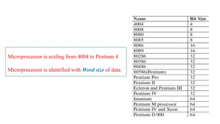
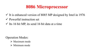
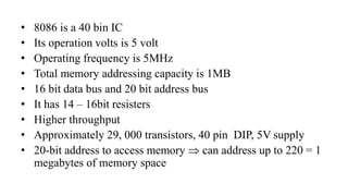
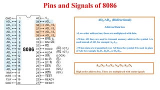
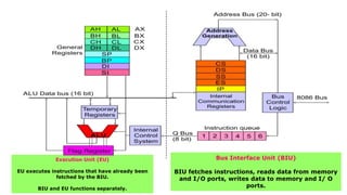
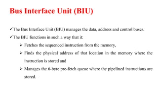
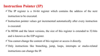
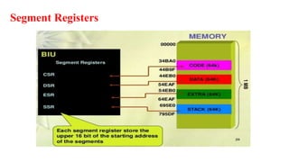
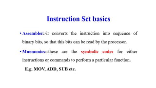
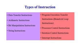
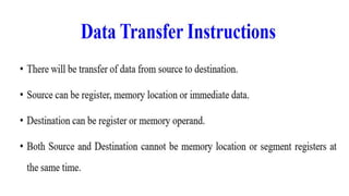
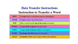
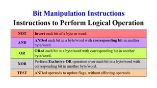
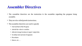
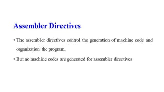
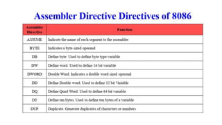
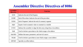
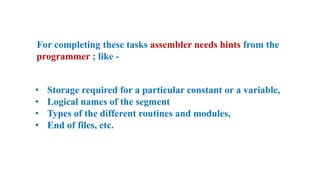
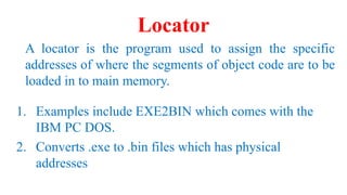
This document provides an outline for a course on microprocessors and microcontrollers. The course is divided into 5 units:
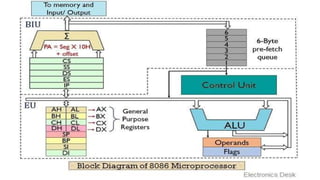
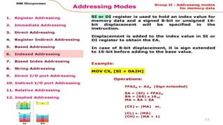
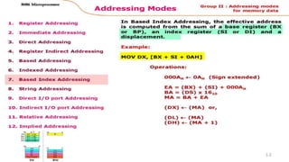
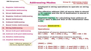
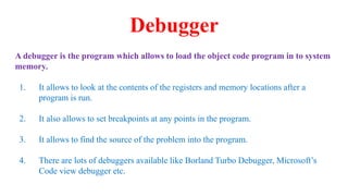
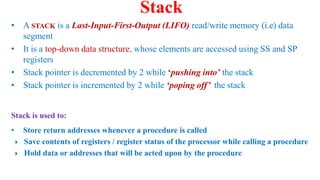
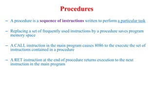
1. The 8086 microprocessor, covering its architecture, instruction set, assembly language programming, and interrupts.
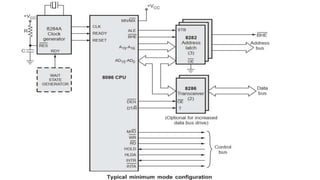
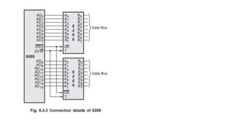
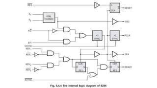
2. The 8086 system bus structure, including I/O programming, multiprogramming, and advanced processors.
3. I/O interfacing with the 8086, including parallel and serial interfaces.
4. The 8051 microcontroller architecture and assembly language programming.
5. Interfacing with the 8051, including timers, serial ports, interrupts, and interfacing with devices like LCDs, keyboards, and sensors.


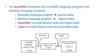
![Assembly Language Programming
High Level language Assembly Programming
Assembler
[1200] -> Address
1200 -> Register](https://image.slidesharecdn.com/ec8691microprocessorandmicrocontroller-240227145311-d7ca0707/85/EC-8691-Microprocessor-and-Microcontroller-pptx-93-320.jpg)
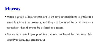
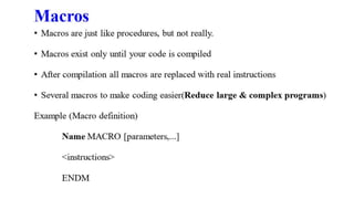
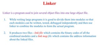
![• A macro is the repeatedly appearing group of instructions, that is given a name
at the start of the program.
• A macro can be defined anywhere in a program using the directives MACRO
and ENDM
Defining a Macro:
name MACRO [optional arguments]
statements..
statements..
ENDM
Macro](https://image.slidesharecdn.com/ec8691microprocessorandmicrocontroller-240227145311-d7ca0707/85/EC-8691-Microprocessor-and-Microcontroller-pptx-121-320.jpg)