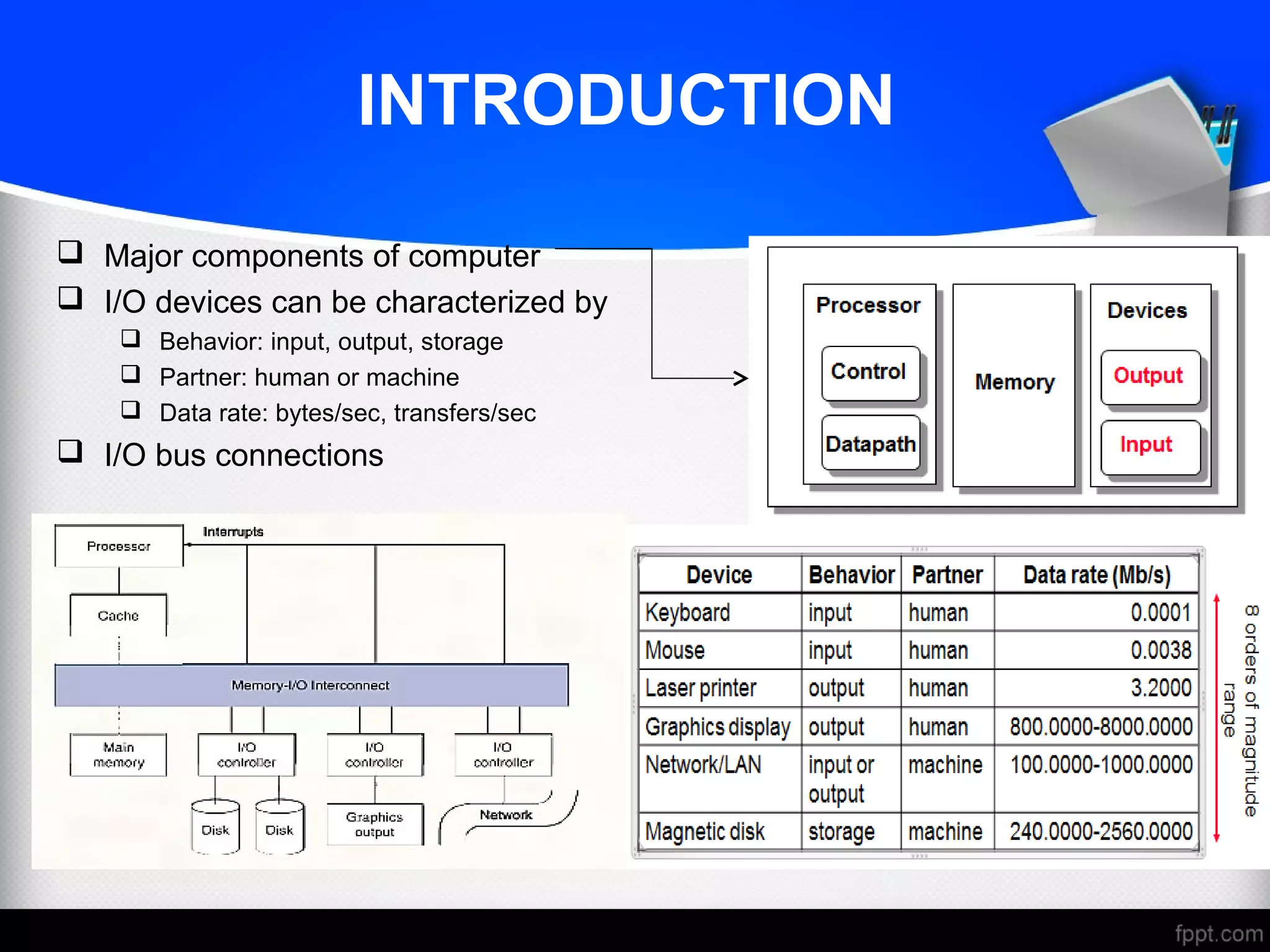
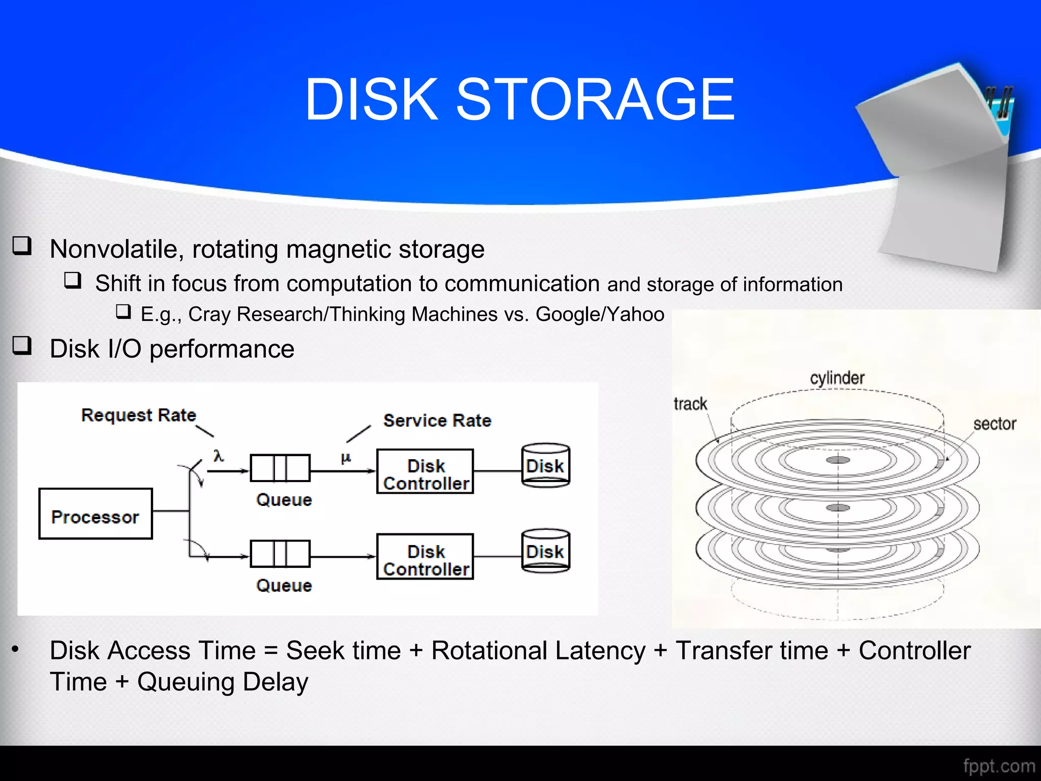
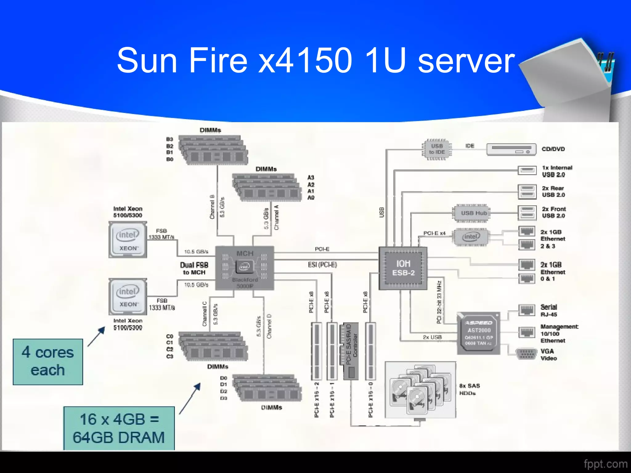
DESIGN A I/ODESIGN A I/O
SYSTEMSYSTEM
INTRODUCTION
 Major components of computer
 I/O devices can be characterized by
 Behavior: input, output, storage
 Partner: human or machine
 Data rate: bytes/sec, transfers/sec
 I/O bus connections
I/O SYSTEM CHARACTERISTICS
AND ISSUES
 Dependability is important
 Particularly for storage devices
 Performance measures
 Latency (response time)
 Throughput (bandwidth)
 Desktops & embedded systems
 Mainly interested in response time & diversity of devices
 Servers
 Mainly interested in throughput & expandability of devices
 I/O System Design Issues
 Performance
 Expandability
 Resilience in the face of failure
DISK STORAGE
 Nonvolatile, rotating magnetic storage
 Shift in focus from computation to communication and storage of information
 E.g., Cray Research/Thinking Machines vs. Google/Yahoo
 Disk I/O performance
• Disk Access Time = Seek time + Rotational Latency + Transfer time + Controller
Time + Queuing Delay
DISK ACCESS AND SECTOR
 Each sector records
 Sector ID
 Data (512 bytes, 4096 bytes proposed)
 Error correcting code (ECC)
 Used to hide defects and recording errors
 Synchronization fields and gaps
 Access to a sector involves
 Queuing delay if other accesses are pending
 Seek: move the heads
 Rotational latency
 Data transfer
 Controller overhead
DISK PERFORMANCE ISSUES
 Manufacturers quote average seek time
 Based on all possible seeks
 Locality and OS scheduling lead to smaller actual average seek times
 Smart disk controller allocate physical sectors on disk
 Present logical sector interface to host
 SCSI, ATA, SATA
 Disk drives include caches
 Prefetching sectors in anticipation of access
 Avoid seek and rotational delay
INTERCONNECTING
COMPONENTS
 Need interconnections between
 CPU, memory, I/O controllers
 Bus: shared communication channel
 Parallel set of wires for data and synchronization of data transfer
 Can become a bottleneck
 Performance limited by physical factors
 Wire length, number of connections
 More recent alternative: high-speed serial connections with switches
 Like networks
BUS TYPES
 A bus is a shared communication link (a single set of wires used to connect
multiple subsystems) that needs to support a range of devices with widely varying
latencies and data transfer rates
 Processor-Memory buses
 Short, high speed
 Design is matched to memory organization
 I/O buses
 Longer, allowing multiple connections
 Specified by standards for interoperability
 Connect to processor-memory bus through a bridge
BUS SIGNALS AND
SYNCHRONIZATION
 Data lines
 Carry address and data
 Multiplexed or separate
 Control lines
 Indicate data type, synchronize transactions
 Synchronous
 Uses a bus clock
 Asynchronous
 Uses request/acknowledge control lines for handshaking
I/O MANAGEMENT
 I/O is mediated by the OS
 Multiple programs share I/O resources
 Need protection and scheduling
 I/O causes asynchronous interrupts
 Same mechanism as exceptions
 I/O programming is fiddly
 OS provides abstractions to programs
I/O COMMANDS
 I/O devices are managed by I/O controller hardware
 Transfers data to/from device
 Synchronizes operations with software
 Command registers
 Cause device to do something
 Status registers
 Indicate what the device is doing and occurrence of errors
 Data registers
 Write: transfer data to a device
 Read: transfer data from a device
I/O REGISTER MAPPING
 Memory mapped I/O
 Registers are addressed in same space as memory
 Address decoder distinguishes between them
 OS uses address translation mechanism to make them only accessible to kernel
 I/O instructions
 Separate instructions to access I/O registers
 Can only be executed in kernel mode
 Example: x86
POLLING
 Periodically check I/O status register
 If device ready, do operation
 If error, take action
 Common in small or low-performance real-time embedded systems
 Predictable timing
 Low hardware cost
 In other systems, wastes CPU time
INTERRUPTS
 When a device is ready or error occurs
 Controller interrupts CPU
 Interrupt is like an exception
 But not synchronized to instruction execution
 Can invoke handler between instructions
 Cause information often identifies the interrupting device
 Priority interrupts
 Devices needing more urgent attention get higher priority
 Can interrupt handler for a lower priority interrupt
I/O DATA TRANSFER
 Polling and interrupt-driven I/O
 CPU transfers data between memory and I/O data registers
 Time consuming for high-speed devices
 Direct memory access (DMA)
 OS provides starting address in memory
 I/O controller transfers to/from memory autonomously
 Controller interrupts on completion or error
DMA AND CACHE INTERACTION
 If DMA writes to a memory block that is cached
 Cached copy becomes stale
 If write-back cache has dirty block, and DMA reads memory block
 Reads stale data
 Need to ensure cache coherence
 Flush blocks from cache if they will be used for DMA
 Or use non-cacheable memory locations for I/O
TRANSACTION PROCESSING
BENCHMARKS
 Transactions
 Small data accesses to a DBMS
 Interested in I/O rate, not data rate
 Measure throughput
 Subject to response time limits and failure handling
 ACID (Atomicity, Consistency, Isolation, Durability)
 Overall cost per transaction
 Transaction Processing Council (TPC) benchmarks (www.tcp.org)
 TPC-APP: B2B application server and web services
 TCP-C: on-line order entry environment
 TCP-E: on-line transaction processing for brokerage firm
 TPC-H: decision support — business oriented ad-hoc queries
FILE SYSTEM & WEB
BENCHMARKS
 SPEC System File System (SFS)
 Synthetic workload for NFS server, based on monitoring real systems
 Results
 Throughput (operations/sec)
 Response time (average ms/operation)
 SPEC Web Server benchmark
 Measures simultaneous user sessions, subject to required throughput/session
 Three workloads: Banking, Ecommerce, and Support
I/O SYSTEM DESIGN
 Satisfying latency requirements
 For time-critical operations
 If system is unloaded
 Add up latency of components
 Maximizing throughput
 Find “weakest link” (lowest-bandwidth component)
 Configure to operate at its maximum bandwidth
 Balance remaining components in the system
 If system is loaded, simple analysis is insufficient
 Need to use queuing models or simulation
Rack-Mounted Servers
Sun Fire x4150 1U server
I/O System Design Example
 Given a Sun Fire x4150 system with
 Workload: 64KB disk reads
 Each I/O op requires 200,000 user-code instructions and 100,000 OS instructions
 Each CPU: 109 instructions/sec
 FSB: 10.6 GB/sec peak
 DRAM DDR2 667MHz: 5.336 GB/sec
 PCI-E 8× bus: 8 × 250MB/sec = 2GB/sec
 Disks: 15,000 rpm, 2.9ms avg. seek time, 112MB/sec transfer rate
 What I/O rate can be sustained?
 For random reads, and for sequential read
Design Example (cont.)
Pitfall: Offloading to I/O Processors
 Overhead of managing I/O processor request may dominate
 Quicker to do small operation on the CPU
 But I/O architecture may prevent that
 I/O processor may be slower
 Since it’s supposed to be simpler
 Making it faster makes it into a major system component
 Might need its own coprocessors!
CONCLUSION
 BASICS OF I/O SYSTEM
 I/O CHARACTERISTICS
 DISK
 I/O MANAGEMENT
 I/O DATATYPES
 I/O REGISTERS
 I/O DESIGN
 PITFALL: OFFLOADING TO I/O PROCESSOR

Design an I/O system

  • 1.
    DESIGN A I/ODESIGNA I/O SYSTEMSYSTEM
  • 2.
    INTRODUCTION  Major componentsof computer  I/O devices can be characterized by  Behavior: input, output, storage  Partner: human or machine  Data rate: bytes/sec, transfers/sec  I/O bus connections
  • 3.
    I/O SYSTEM CHARACTERISTICS ANDISSUES  Dependability is important  Particularly for storage devices  Performance measures  Latency (response time)  Throughput (bandwidth)  Desktops & embedded systems  Mainly interested in response time & diversity of devices  Servers  Mainly interested in throughput & expandability of devices  I/O System Design Issues  Performance  Expandability  Resilience in the face of failure
  • 4.
    DISK STORAGE  Nonvolatile,rotating magnetic storage  Shift in focus from computation to communication and storage of information  E.g., Cray Research/Thinking Machines vs. Google/Yahoo  Disk I/O performance • Disk Access Time = Seek time + Rotational Latency + Transfer time + Controller Time + Queuing Delay
  • 5.
    DISK ACCESS ANDSECTOR  Each sector records  Sector ID  Data (512 bytes, 4096 bytes proposed)  Error correcting code (ECC)  Used to hide defects and recording errors  Synchronization fields and gaps  Access to a sector involves  Queuing delay if other accesses are pending  Seek: move the heads  Rotational latency  Data transfer  Controller overhead
  • 6.
    DISK PERFORMANCE ISSUES Manufacturers quote average seek time  Based on all possible seeks  Locality and OS scheduling lead to smaller actual average seek times  Smart disk controller allocate physical sectors on disk  Present logical sector interface to host  SCSI, ATA, SATA  Disk drives include caches  Prefetching sectors in anticipation of access  Avoid seek and rotational delay
  • 7.
    INTERCONNECTING COMPONENTS  Need interconnectionsbetween  CPU, memory, I/O controllers  Bus: shared communication channel  Parallel set of wires for data and synchronization of data transfer  Can become a bottleneck  Performance limited by physical factors  Wire length, number of connections  More recent alternative: high-speed serial connections with switches  Like networks
  • 8.
    BUS TYPES  Abus is a shared communication link (a single set of wires used to connect multiple subsystems) that needs to support a range of devices with widely varying latencies and data transfer rates  Processor-Memory buses  Short, high speed  Design is matched to memory organization  I/O buses  Longer, allowing multiple connections  Specified by standards for interoperability  Connect to processor-memory bus through a bridge
  • 9.
    BUS SIGNALS AND SYNCHRONIZATION Data lines  Carry address and data  Multiplexed or separate  Control lines  Indicate data type, synchronize transactions  Synchronous  Uses a bus clock  Asynchronous  Uses request/acknowledge control lines for handshaking
  • 10.
    I/O MANAGEMENT  I/Ois mediated by the OS  Multiple programs share I/O resources  Need protection and scheduling  I/O causes asynchronous interrupts  Same mechanism as exceptions  I/O programming is fiddly  OS provides abstractions to programs
  • 11.
    I/O COMMANDS  I/Odevices are managed by I/O controller hardware  Transfers data to/from device  Synchronizes operations with software  Command registers  Cause device to do something  Status registers  Indicate what the device is doing and occurrence of errors  Data registers  Write: transfer data to a device  Read: transfer data from a device
  • 12.
    I/O REGISTER MAPPING Memory mapped I/O  Registers are addressed in same space as memory  Address decoder distinguishes between them  OS uses address translation mechanism to make them only accessible to kernel  I/O instructions  Separate instructions to access I/O registers  Can only be executed in kernel mode  Example: x86
  • 13.
    POLLING  Periodically checkI/O status register  If device ready, do operation  If error, take action  Common in small or low-performance real-time embedded systems  Predictable timing  Low hardware cost  In other systems, wastes CPU time
  • 14.
    INTERRUPTS  When adevice is ready or error occurs  Controller interrupts CPU  Interrupt is like an exception  But not synchronized to instruction execution  Can invoke handler between instructions  Cause information often identifies the interrupting device  Priority interrupts  Devices needing more urgent attention get higher priority  Can interrupt handler for a lower priority interrupt
  • 15.
    I/O DATA TRANSFER Polling and interrupt-driven I/O  CPU transfers data between memory and I/O data registers  Time consuming for high-speed devices  Direct memory access (DMA)  OS provides starting address in memory  I/O controller transfers to/from memory autonomously  Controller interrupts on completion or error
  • 16.
    DMA AND CACHEINTERACTION  If DMA writes to a memory block that is cached  Cached copy becomes stale  If write-back cache has dirty block, and DMA reads memory block  Reads stale data  Need to ensure cache coherence  Flush blocks from cache if they will be used for DMA  Or use non-cacheable memory locations for I/O
  • 17.
    TRANSACTION PROCESSING BENCHMARKS  Transactions Small data accesses to a DBMS  Interested in I/O rate, not data rate  Measure throughput  Subject to response time limits and failure handling  ACID (Atomicity, Consistency, Isolation, Durability)  Overall cost per transaction  Transaction Processing Council (TPC) benchmarks (www.tcp.org)  TPC-APP: B2B application server and web services  TCP-C: on-line order entry environment  TCP-E: on-line transaction processing for brokerage firm  TPC-H: decision support — business oriented ad-hoc queries
  • 18.
    FILE SYSTEM &WEB BENCHMARKS  SPEC System File System (SFS)  Synthetic workload for NFS server, based on monitoring real systems  Results  Throughput (operations/sec)  Response time (average ms/operation)  SPEC Web Server benchmark  Measures simultaneous user sessions, subject to required throughput/session  Three workloads: Banking, Ecommerce, and Support
  • 19.
    I/O SYSTEM DESIGN Satisfying latency requirements  For time-critical operations  If system is unloaded  Add up latency of components  Maximizing throughput  Find “weakest link” (lowest-bandwidth component)  Configure to operate at its maximum bandwidth  Balance remaining components in the system  If system is loaded, simple analysis is insufficient  Need to use queuing models or simulation
  • 20.
  • 21.
    Sun Fire x41501U server
  • 22.
    I/O System DesignExample  Given a Sun Fire x4150 system with  Workload: 64KB disk reads  Each I/O op requires 200,000 user-code instructions and 100,000 OS instructions  Each CPU: 109 instructions/sec  FSB: 10.6 GB/sec peak  DRAM DDR2 667MHz: 5.336 GB/sec  PCI-E 8× bus: 8 × 250MB/sec = 2GB/sec  Disks: 15,000 rpm, 2.9ms avg. seek time, 112MB/sec transfer rate  What I/O rate can be sustained?  For random reads, and for sequential read
  • 23.
  • 25.
  • 26.
    Pitfall: Offloading toI/O Processors  Overhead of managing I/O processor request may dominate  Quicker to do small operation on the CPU  But I/O architecture may prevent that  I/O processor may be slower  Since it’s supposed to be simpler  Making it faster makes it into a major system component  Might need its own coprocessors!
  • 27.
    CONCLUSION  BASICS OFI/O SYSTEM  I/O CHARACTERISTICS  DISK  I/O MANAGEMENT  I/O DATATYPES  I/O REGISTERS  I/O DESIGN  PITFALL: OFFLOADING TO I/O PROCESSOR