The document summarizes Satadru Das' summer internship exploring quantum technologies at IIT Madras from May to July 2019. It discusses three approaches to building an optical Ising machine using optical parametric oscillators. It also covers several quantum key distribution protocols including BB84, DPS-QKD and E91. Finally, it describes experiments performed on fiber optic communication systems, including characterization of WDM components, fiber Bragg gratings, optical time domain reflectometry and more. The internship provided an opportunity for Satadru to learn about active research in quantum computing, communication and related fiber optic experiments.

![4
The Hamiltonian of an Ising model with N spins is given by the equation:
H = −
N
ij
Jijσiσj −
i
hiσi (1)
With Jij being the coupling between ith
and jth
spins, and σi and σj representing the z-projection
of the spins, the eigenvalues of which are +1 or -1 and hi is the local field.
2.3 Optical Ising Machine Setup and Designs
There are more than one way to construct an Ising machine using OPOs but in this report I will
explain mainly the Ising machine that was demonstrated at Stanford in an experiment led by Alireza
Marandi.
One crucial component of these setups is Optical Parametric Oscillator(OPO). OPO is a device
similar to a laser. An OPO, unlike a conventional laser, produces light that is either exactly in or
exactly out of phase with respect to some reference light. It converts an input laser wave (called
”pump”) with frequency ωp into two output waves of lower frequency (ωs, ωi) by means of second-
order nonlinear optical interaction. The sum of the output waves’ frequencies is equal to the input
wave frequency: ωs + ωi = ωp. For historical reasons, the two output waves are called ”signal” and
”idler”, where the output wave with higher frequency is the ”signal”.
Individual atoms and their electron spins are difficult to work with, so the Ising machine I
studied have been focused on building a machine that implements the Ising model using pulses of
light in place of electron spins. The phases of these OPO pulses will ultimately act as the spins in
the Ising model. The Ising problem is mapped onto the pulses and the interactions between them.
The result is assessed in terms of the problem’s total energy, with the lowest energy state as the
optimal solution. Then this solution is translated into what it means for the original problem. Here
“spin up” is represented as the condition in which the light from the OPO is in phase with the
reference light and, conversely, “spin down” if it is out of phase.
There were two schemes that were demonstrated:
2.3.1 Optical Delay Line Coupling Scheme
[1, 2] In this configuration, N independent OPOs are simultaneously realized as N optical pulses
circulation in a single fiber ring cavity with an internal phase-sensitive amplifier (PSA) which is
driven externally pump pulse trains. A part of each of the OPO pulse circulating in a fiber ring
resonator is picked-off at every round trip by the output coupler, amplified by an external PSA,
split into multiple optical delay lines including intensity and phase modulators and then inject back
to the target OPO pulse at appropriate timing. Using N − 1 optical delay lines, any jth
pulse can
be connected to any other ith
pulse with a coupling constant Jij.
Study And Exploration of Some Hot Quantum Technologies; Satadru Das; 1 May 2019 - 9 July
2019](https://image.slidesharecdn.com/internshipreport-190801134154/85/Summer-Internship-Report-2019-5-320.jpg)
![5
Figure 1: Optical delay line coupling scheme[1]
2.3.2 Measurement-Feedback Coupling Scheme
[1, 2] This is an alternative coupling scheme to implement the Ising coupling Jij. Instead of
directly connecting the OPO pulses with optical delay lines, we can measure approximately the
in-phase amplitude of the internal DOPO pulse by the optical balanced homodyne detectors. If
the inferred in-phase amplitude of the jth
OPO pulse is represented by ˜Xj, the feedback pulse
to ith
OPO pulse should have an in-phase amplitude proportional to j Jij
˜Xj. The complicated
task of the synchronous computation of the vector-vector multiplication between Jij and ˜Xj, is
achieved by a single measurement-feedback circuit consisting of an analog-to-digital converter, a
field programmable gate array (FPGA), its here that the Ising problem itself is represented, a
digital-to-analog converter and optical amplitude/phase modulators. The feedback pulse used as
an input to the optical modulator and the local oscillator pulse (LO pulse) used for optical homodyne
detection are both provided by a part of the pump laser output. Basically, the FPGA applies that
calculation to the settings of an intensity modulator and a phase modulator that sit in the path of
one branch of the reference pulse. The newly modified reference pulse is then fed into the optical-
fiber ring where the OPO pulses are zipping past. We repeat the whole process for each OPO
pulse in the loop, and it can take tens to hundreds of trips around the loop for all the pulses to
achieve their final phase states. Once that’s done, a separate computer reads off the set of phases,
interprets them as either spin-up or spin-down electrons in the Ising problem, and then translates
that into a meaningful solution to the original optimization problem you wanted to solve. Such
measurement-feedback coupling scheme is equivalent to an optical delay line coupling scheme.
Study And Exploration of Some Hot Quantum Technologies; Satadru Das; 1 May 2019 - 9 July
2019](https://image.slidesharecdn.com/internshipreport-190801134154/85/Summer-Internship-Report-2019-6-320.jpg)
![6
Figure 2: Measurement feedback coupling scheme[1]
In their final state, these pulses oscillate as optical parametric oscillators (OPOs) with either
a 0 or a π phase with respect to the pump light, and these two phases can be used to encode up
or down spin directions. Coupling between pulses can be arranged in such a way that the system
preferentially oscillates in a configuration that minimizes the Hamiltonian in equation. The sign of
the phases of the pulses can then be measured and mapped onto spin orientations in an Ising model,
in which the spin-spin coupling is determined by the optical coupling. The system preferentially
settles into a configuration that corresponds to a low energy in the Ising model.
The advantage of measurement feedback scheme is that all-to-all coupling of the order of ∼ N2
connections can be implemented by a single measurement-feedback circuit, so that the daunting
task of constructing N − 1 optical delay lines and stabilizing their delay lengths (or optical phase)
with an error much less than the optical wavelength can be avoided. On the other hand, the optical
delay line coupling scheme enjoys its inherent-speed operation with a pulse repetition frequency
limited only by optical device performance. One disadvantage of the optical delay line scheme
is that even a vibration created by someone emptying a nearby waste bin could cause a subtle
expansion or contraction in the delay lines.
2.3.3 Chip based Approach
[3] The problem that arises with the above setup is complexity in scalability. Hewlett Packard
Enterprise(HPE) in Palo Alto, California reported a chip scale Optical Ising Machine. The HPE
chip is designed to be a compact approach that doesn’t need such electronic feedback. Four areas
on the chip, called nodes, support four spins made of infrared light. After the light exits each
node, it is split up and combined with light from each of the other nodes inside an interferometer.
Electric heaters built into the interferometer are used to alter the index of refraction and physical
size of nearby components. This adjusts the optical path length of each light beam—and thus its
phase relative to the other beams. The heater temperatures encode the problem to be solved, as
they determine how strongly the state of one spin is weighed against another when two beams are
Study And Exploration of Some Hot Quantum Technologies; Satadru Das; 1 May 2019 - 9 July
2019](https://image.slidesharecdn.com/internshipreport-190801134154/85/Summer-Internship-Report-2019-7-320.jpg)
![7
combined. The outputs of all these interactions are then condensed and fed back into the nodes,
where structures called microring resonators clean up the light in each node so it once again has one
of two phases. The light cycles over and over through the interferometer and the nodes, flipping
spins between phases of 0 degrees and 180 degrees until the system equilibrates to a single answer.
Basically, when the system turns on, light runs through all the nodes at once, and every node works
at the same time to find the most efficient connection path.
3 Quantum Key Distribution
3.1 Introduction
Cryptography provides the means to securely communicate data between authorized entities by
using mathematical transformations which utilize pre-shared cryptographic keys. The need to share
key material with authorized entities in a secure, efficient and timely manner has driven efforts to
develop new key distribution methods. The most promising method is Quantum Key Distribution
(QKD) and is considered to be “unconditionally secure” because it relies upon the immutable laws
of quantum physics rather than computational complexity as the basis for its security. A third
party eavesdropping on a QKD quantum channel would be detected because the observation would
introduce errors in the quantum channel. Since the purpose of cryptography is to ensure that the
information is not readable by an eavesdropper, the fact that in “multiplexing” an eavesdropper
invariably destroys an intercepted message upon reading it was seen as an obtainable holy grail of
cryptography and the field of quantum cryptography came into being.
3.2 BB84 Protocol
[6, 7] The first true quantum key distribution protocol was proposed by Charles Bennett and
Gilles Brassard (Bennett & Brassard, 1984). Bennett and Brassard proposed a protocol, known as
BB84. The basis of security for BB84, along with most QKD protocols, is that an eavesdropper
will induce a measurable error in the quantum channel, allowing for their presence to be detectable
by the sender and receiver. Qubits are created by using photons polarized using mutually unbiased
polarization bases. There are several types of polarization that can be chosen including rectilinear
or 0 and 90 degree polarization, diagonal or 45 and 135 degree polarization.
BB84 utilizes the rectilinear and diagonal bases for encoding photons into qubits. The goal
of BB84 is to satisfy the requirements of an encryption scheme known as One Time Pad (OTP).
OTP is a completely secure encryption method if the key generation is truly random and the key
is the same length as the message to be encrypted. In BB84, Alice, the sender, randomly generates
photons in 0◦
, 45◦
, 90◦
, or 135◦
polarizations.
Alice generates the key material by randomly choosing key bits and basis. For BB84, a 0 is
encoded as either a 90◦
polarized photon in the rectilinear basis or as a 45◦
polarized photon in the
diagonal basis. Likewise, a 1 is encoded as a 0◦
polarization photon in the rectilinear basis or as a
135◦
polarized photon in the diagonal basis. Alice records the polarization state, basis and time that
each photon is sent to Bob, and transmits the photons through the quantum channel one at a time.
Bob, the receiver, receives the encoded photons and measures their polarization states, choosing his
measurement basis randomly. Bob then records the measurement basis, the measured polarization
state, and the time the photon was received. Since both the basis encoding and measurement is
random, Bob can expect to correctly choose the right measurement basis 50% of the time. Once
Study And Exploration of Some Hot Quantum Technologies; Satadru Das; 1 May 2019 - 9 July
2019](https://image.slidesharecdn.com/internshipreport-190801134154/85/Summer-Internship-Report-2019-8-320.jpg)
![8
the entire key is transmitted, Alice and Bob utilize the classical channel to compare Alice’s actual
basis versus Bob’s measured basis, discarding all improperly measured qubits for which the bases
were mismatched. The key material remaining is called the sifted key. At this point, if there were
no errors in transmission, Alice and Bob should have an identical, random key.
Figure 3: BB84 protocol[10]
3.3 Differential Phase Shift Quantum Key Distribution (DPS-QKD) Pro-
tocol
[5] Optical fibers have been the most popular quantum channel to date, but the polarization states,
which were initially proposed in BB84, cannot be maintained stably over a long distance. Instead
the phase basis (the relative phase of a photon extending over two pulses is either 0 or π) can be
used. Alternatively one can use two bases for relative phases {0, π} or {π/2, 3π/2}.
Figure 4: Photon encoding in light pulses[11]
First of all, the sender (Alice) prepares a coherent pulse train and modulates the relative phase
of the light pulses randomly with 0 or π. The light is then sent to the receiver (Bob) after being
attenuated such that the number of photons per pulse in less than 1. Bob uses a one pulse delay
Study And Exploration of Some Hot Quantum Technologies; Satadru Das; 1 May 2019 - 9 July
2019](https://image.slidesharecdn.com/internshipreport-190801134154/85/Summer-Internship-Report-2019-9-320.jpg)
![9
interferometer to cause successive pulses to interfere and measure the relative phase information
with a set of photon detectors located at the interferometer outputs. Since the source photon power
is weak, only part of the relative phase information can be read out, but the obtained relative phase
should be exactly the same as the phase modulation of the sender. Bob records the timestamp
when a photon was detected and which of the detectors clicked (relative phase information itself).
He then generates a key by assigning bit 0 to relative phase 0 and bit 1 to relative phase π. Bob
then sends back to Alice only the timestamp information. Alice uses this information and her phase
encoding records to generate a key, which is called the sifted key. Finally, after error-correction and
privacy amplification processes, final secure keys are generated and used in cryptic communication.
[4] Here is a brief description of 3-pulse DPS QKD. Any two consecutive pulse experiences nearly
similar phase and polarization changes along the optical fiber channel. Preservation of relative phase
and polarizations coupled with ease of implementation makes the DPS scheme a suitable candidate
for long distance fiber based implementation.
Figure 5: Alice Bob setup for 3 pulse DPS QKD
Figure 6: Output of MZI
In Fig5, the setup of 3 pulse DPS-QKD is shown. The setup is such that the time delay between
(1) and (2) are equal to the time delay between (2)and(3) and also the time delay between (4) and
(5). Let’s call that time delay as Td. Now when Alice sends a photon, it has equal probability of
going through paths (1),(2) or (3) so basically the photon sent by Alice will be in a superposition
of 3 pulses. For 1 photon the probability of photon traveling through either of path (1),(2) and(3)
will be 1/3 for each path. This superposition of these 3 pulses will now pass through an unbalanced
Mach-Zehnder interferometer(MZI) which is with Bob. Now because there are two paths in the
Study And Exploration of Some Hot Quantum Technologies; Satadru Das; 1 May 2019 - 9 July
2019](https://image.slidesharecdn.com/internshipreport-190801134154/85/Summer-Internship-Report-2019-10-320.jpg)
![10
MZI namely (4) and (5), the probability of each of the pulse further reduces to half for each of
these two paths and because of the time delay, the number of pulses coming out of MZI will be 4
as shown in Fig 6. In short, Bob will detect 4 pulses.
The probability of the photon on each of the pulses at different time is given in the table below.[4]
Time Instant Probable Paths Probability of Detection
I 1-4 1/6
II 2-4 or 3-5 1/6 + 1/6 = 1/3
III 2-5 or 3-4 1/6 + 1/6 =1/3
IV 3-5 1/6
We can see from the table that the probability of the first pulse and the last pulse are pretty low
compared to the 2nd
and 3rd
pulse and due to their high probability they are the only pulses which
contribute in the key generation. Due to their low probability the detection of first and last time
slot results in random clicking of the detectors. So, if we can generalise the entire thing to certain
things such as there are not 3 but n different paths in the Alice part of the setup and instead of
1 Alice transmits N photons, then each photons will be in a superposition of n pulses and only
N(n−1)/n contribute to the final key. (n−1)/n term is called as shifted key rate and it is denoted
by Rshift . So the probability of photon in the first and the last time slot is 1/(n) ∗ 1/2 = 1/2n
and the photon probability for the remaining n-1 pulses will be 1/2n + 1/2n = 1/n .
So basically after pulses are detected by either of Detector 1 (DET1) or Detector 2 (DET 2), Bob
lets Alice know the time instances of either of the detector’s clicks through public channel using
which they would generate a key. Depending upon the sequence of detectors clicks Alice would
know if the key is compromised or not. From the information given by Bob and her modulation
data, Alice would know which detector clicked on Bob’s site. DET1 click represents 0 and DET
2 click represents 1 from which they can have an identical bit string. Since Bob is only telling
the time instances to Alice, no bit information is leaked to the public. . The pulses sent by Alice
are phase modulated by two nonorthogonal basis {0,π} and {π/2, 3π/2}. Then Bob measures the
phase difference either in {0,π} basis or {π/2, 3π/2} basis.
In case of intercept/resend attack using the same setup as Bob, Eve detects a photon at four
possible time instances as Bob does. She obtains partial information when a photon is counted at
(ii) or (iii), while she gets no information when it is counted at (i) or (iv). From the measurement at
(ii) or (iii), Eve knows one of the two phase-differences. If Eve sends a photon split into two pulses
having the measured phase difference, she changes the counting rate at each time-instance in Bob.
When Eve measures the phase difference between the first two pulses and resends a fake photon
accordingly, Bob counts the photon at time-instances (i), (ii), or (iii). The probability ratio of the
click at (i), (ii), and (iii) is 1:2:1. When Eve measures the phase difference between the second two
pulses, Bob’s detectors can click at time-instances (ii), (iii), and (iv) with a probability ratio of
1:2:1. Thus, the overall ratio of the clicks at (i), (ii), (iii), and (iv) becomes 1:3:3:1. On the other
hand, the counting ratio for a photon split into three pulses is 1:2:2:1. Therefore, this cheating is
revealed by monitoring the counting rate at each time-instance.
3.4 E91 Protocol
[6, 7] This protocol was proposed by Artur Ekert. It uses entangled pairs of photons. hese can be
created by Alice, by Bob, or by some source separate from both of them, including eavesdropper
Study And Exploration of Some Hot Quantum Technologies; Satadru Das; 1 May 2019 - 9 July
2019](https://image.slidesharecdn.com/internshipreport-190801134154/85/Summer-Internship-Report-2019-11-320.jpg)
![11
Eve. The photons are distributed so that Alice and Bob each end up with one photon from each
pair.
What is quantum entanglement? . It is possible for two particles to become entangled such that
when a particular property is measured in one particle, the opposite state will be observed on the
entangled particle instantaneously. This is true regardless of the distance between the entangled
particles. It is impossible, however to predict prior to measurement what state will be observed
thus it is not possible to communicate via entangled particles without discussing the observation
over classical channel.
The scheme relies on two properties of entanglement. First, the entangled states are perfectly
correlated in the sense that if Alice and Bob both measure whether their particles have vertical
or horizontal polarizations, they always get the same answer with 100% probability. The same
is true if they both measure any other pair of complementary (orthogonal) polarizations. This
necessitates that the two distant parties have exact directionality synchronization. However, the
particular results are completely random; it is impossible for Alice to predict if she (and thus Bob)
will get vertical polarization or horizontal polarization. Second, any attempt at eavesdropping by
Eve destroys these correlations in a way that Alice and Bob can detect.
Figure 7: E19 Protocol[12]
3.5 Quantum Bit Error Rate (QBER)
[8] In real systems, the secure key’s generation rate and distribution distance are limited by the
sensitivity, dark count rate of single photon detector, and the loss of the quantum channel.
The expression for QBER given by Bennet and Brassard for the polarization based BB84 is:
QBER =
1
2
(1 − Veff )psignal + px + db
psignal + px + db
(2)
Where psignal is the probability coming from the detection of signal photons, dB is the dark
count probability related to the noise source coming from photon detection and Veff represents
the effective visibility due to the imperfections of the devices employed in the system and the fiber
dispersion. px is the crosstalks probability and takes into account the photon crosstalk contributions
measured at each optical detector which contribute to a false detection.
The QBER is defined as the wrong bits to the total number of bits received and is normally on
the order of few percentage.
Study And Exploration of Some Hot Quantum Technologies; Satadru Das; 1 May 2019 - 9 July
2019](https://image.slidesharecdn.com/internshipreport-190801134154/85/Summer-Internship-Report-2019-12-320.jpg)
![13
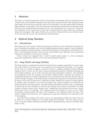
= QBERopt + QBERdet + QBERacc (10)
QBERopt is independent of the transmission distance(basically independent of tlink). It can be
considered as a measure of the optical quality of the setup, depending only on the polarization
or interference fringe contrast. The technical effort needed to obtain and, more importantly, to
maintain a given QBERopt is an important criterion for evaluating different quantum channels. In
fiber based Quantum Channels (QC), the problem is to maintain this value in spite of polarization
fluctuations and depolarization in the fiber link. For a phase-coding setup, QBERopt and the
interference visibility are related by:
QBERopt =
1 − V
2
(11)
For the second contribution, QBERdet is essentially independent of the fiber length, it is detector
noise that limits the transmission distance.
The QBERacc contribution is present only in two-photon schemes in which multiphoton pulses
are processed in such a way that they do not necessarily encode the same bit value.
3.6 Quantum Error Correction(QEC)
[9] The raw key is obtained by a process called ”sifting” consisting of retaining only the results
obtained when the bases used for measurement are same. After key sifting, another process called
key distillation must be performed. This process entails three steps: error correction, privacy am-
plification and authentication in order to counter any information leakage from photon interception,
eavesdropping detection (with the no-cloning theorem: The no cloning theorem is a result of quan-
tum mechanics which forbids the creation of identical copies of an arbitrary unknown quantum
state ) and exploitation of information announced over the public channel.
The no cloning theorem prevents us from using classical error correction techniques on quantum
states. For example, we cannot create backup copies of a state in the middle of a quantum compu-
tation, and use them to correct subsequent errors. The no-cloning theorem protects the uncertainty
principle in quantum mechanics. If one could clone an unknown state, then one could make as many
copies of it as one wished, and measure each dynamical variable with arbitrary precision, thereby
bypassing the uncertainty principle. This is prevented by the non-cloning theorem.
Error correction is also called Information reconciliation and can be performed with two proce-
dures: one possibility is to correct the errors using parity coding while the other discards errors by
locating error-free subsections of the sifted key.
Privacy amplification means compression of an initial key into a shorter key so that the amount
of private information known to Eve reduces to an exponentially decreasing function of a security
parameter.
Study And Exploration of Some Hot Quantum Technologies; Satadru Das; 1 May 2019 - 9 July
2019](https://image.slidesharecdn.com/internshipreport-190801134154/85/Summer-Internship-Report-2019-14-320.jpg)
![14
Figure 8: Process of key distillation
The process of key distillation in BB84 can be understood through a simple example. For doing
error correction, Alice and Bob both divide their private key bits in to blocks:
(011)(101)(001) →( 111)(101)(001)
(Bob’s errors are shown in red)
Alice then announces the location of the bit (if any) in each block that differs from the other
two. She flips this bit and so does Bob.
(111)(111)(000) →(011)(110)(000)
Now each of Alice’s block is a codeword of the 3-bit repetition code. Bob decodes his block by
majority voting. If there is no more than one error in a block of three, the Bob’s decoded bit agrees
with Alice’s.
(1)(1)(0) →(1)(1)(0)
After error correction, Alice and Bob are likely to share the same bits. Next they perform pri-
vacy amplification to extract bits that are more secure. For example Alice and Bob might divide
their corrected key bits into blocks of three. And in each block compute the parity of the three
bits.
[(1)(1)(0)] [(0)(1)(0)] [(1)(0)(0)] →[0][1][1]
If Eve has a little bit of information about each corrected bit, she’ll know less about the parity bit
of a block.
Study And Exploration of Some Hot Quantum Technologies; Satadru Das; 1 May 2019 - 9 July
2019](https://image.slidesharecdn.com/internshipreport-190801134154/85/Summer-Internship-Report-2019-15-320.jpg)
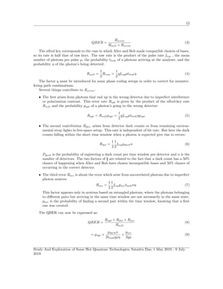
![16
Figure 11: WDM mux and demux[13]
A WDM Mux or Demux is characterized by some important operating characteristics:
• Insertion loss(IL): If Pin is the power entering the Mux at a specific wavelength and Pout is
the power exiting the Mux then the insertion loss of the Mux at this wavelength is defined
by:
IL(dB) = −10log(Pin/Pout) (12)
For calculating the IL of the Mux, we first measure the input power of each laser source
entering the Mux and the output power for that particular wavelength and substitute the
values in the formula above.(One source at a time).
• Cross talks(CT): It refers to how well are different wavelength channels isolated in a given
output. It is defined by:
CT(dB) = 10log(Pj/Pi) (13)
Where Pi is the input signal of the Demux and Pj is the output at each of the separate fiber.
For calculating the CT we measure the input power entering the Demux and the output power
exiting each of the output channels of the Demux and substitute in the formula above.
I took the readings accordingly and measured the IL and CT.
4.2 Characterization of FBG and Characterization(Using FO light run-
ner kit)
Fiber Bragg Grating (FBG) is an optical fiber component having a periodic variation in the reflective
index of its core along the fiber length as shown in Fig 12. A FBG acts lie a highly wavelength
selector reflector, with high reflectivity at a given central wavelength and reflectivity dropping
to very small values close to the central wavelength. The central wavelength, the peak value of
reflectivity and the bandwidth of the reflection spectrum depends on the period of the reflective
index modulation, on the strength of the index modulation of the grating and the length id the
grating. The spectral response is shown in Fig 13. So in simple words a FBG is an inline filter for
wavelengths
Study And Exploration of Some Hot Quantum Technologies; Satadru Das; 1 May 2019 - 9 July
2019](https://image.slidesharecdn.com/internshipreport-190801134154/85/Summer-Internship-Report-2019-17-320.jpg)
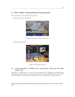
![17
Figure 12: Fiber Bragg Grating
Figure 13: Spectral response of FBG[14]
If Λ is the index of period modulation, L the length of grating and ∆n the index modulation,
then the central wavelength λc, peak reflectivity R and the bandwidth ∆λ(the spectrum width over
which the reflectivity is high) are approximately given by:
λc = 2neΛ (14)
R = tanh2
(π∆nL/λc) (15)
∆λ =
λc
2
neL
(1 + (
∆nL
λc
)2
) (16)
Here ne is the effective index of the fundamental mode of the fiber.
Optical Circulator: An optical circulator is a 3 port optical device designed such that when light
enters from one of its port, it come out at another port. If light enters port 1, it is emitted from
port 2, but some of the emitted light is reflected back to the circulator, it does not come out of port
1 but instead comes out of port 3. Optical circulators also have certain important characteristics:
If P1 is the power entering port 1, P2, and P3 are the output power at port 2 and 3 respectively,
then:
Insertion loss : IL(dB) = −10log(P2/P1) (17)
Cross talk : CT(dB) = 10log(P3/P2) (18)
Reflectivity of FBG =
(P1 − P2)
P1
(19)
Study And Exploration of Some Hot Quantum Technologies; Satadru Das; 1 May 2019 - 9 July
2019](https://image.slidesharecdn.com/internshipreport-190801134154/85/Summer-Internship-Report-2019-18-320.jpg)
![18
Figure 14: The FBG and Optical circulator setup[15]
4.3 Optical add and drop multiplexing (Using the FO Light runner kit)
Optical add drop multiplexer (OADM), mainly is mainly used in wide area and metro area networks,
is used for adding and dropping of optical channels in a fiber link while maintaining the integrity
of other channels For this experiment we used 2 optical circulators, 1 FBG, optical fibers and laser
source. The assembled setup I s shown in Fig 15. The light(4) is reflected back to optical circulator
1 . Basically the red light is being dropped. In optical circulator 2 the red light is being added.
Figure 15: Optical add drop multiplexer[16]
4.4 Bit Error Rate and Eye rate Analysis. (Performed on FO Light
Runner Kit)
In digital communication systems, information is coded in the form of bits represented by 1s and 0s;
In Optical communication each “1” bit is represented by a light pulse and each “0” is represented
by the absence of light pulse. Now as the light pulse propagates through the fiber, it gets affected
by different mechanisms such as dispersion, attenuation, nonlinear effects etc. This results in the
distortion of the received optical pulse which may lead to wrong identifications of 1s and 0s in the
received pulses. Thus the information gets corrupted if the power is too low or the adjacent pulses
start to overlap too much, and hence the receiver can commit errors. This effect is known as Bit
Error Rate (BER).
Study And Exploration of Some Hot Quantum Technologies; Satadru Das; 1 May 2019 - 9 July
2019](https://image.slidesharecdn.com/internshipreport-190801134154/85/Summer-Internship-Report-2019-19-320.jpg)
![19
If the receiver makes n errors in receiver N bits, then the BER is defined defined by n/N.
Errors occur randomly and sometime in bursts. Thus to measure BER it is necessary to count
the errors committed over a period of time and then the average the rate of errors. An incorrect
estimate of BER may take place if short periods of time are chosen.
Figure 16: Eye pattern diagram and its parameters[17]
If we consider a sequence of 3 pulses then the following eight combinations are possible: (0,0,0),
(0,0,1), (0,1,0), (0,1,1), (1,0,0), (1,0,1), (1,1,0), (1,1,1)
Fig 17 show the ideal eye pattern (no jitter w.r.t clock signal), no broadening and no noise.
But it hardly happens so. In general the pulses propagating through the fiber link will accumulate
dispersion, jitter and loss. So the actual Eye pattern would look more like Fig 18.
Figure 17: Clear eye pattern for three pulses[17]
Study And Exploration of Some Hot Quantum Technologies; Satadru Das; 1 May 2019 - 9 July
2019](https://image.slidesharecdn.com/internshipreport-190801134154/85/Summer-Internship-Report-2019-20-320.jpg)
![20
Figure 18: Distorted eye pattern for 3 pulses[17]
Figure 19: The figure shows the eye pattern observed at the Optical Communication Lab, EE
Department, IIT Madras
4.5 Power Budgeting of a Fiber Optic Link. . (Performed on FO Light
Runner Kit)
Let Pr be the power at the receiver, Pt the power of the transmitter, Lc the loss at each connector,
Ls the loss of every splice and let α be the attenuation coefficient (in dB/km) of the fiber. If there
are Nc number of connectors and Ns number of splices, then for a length L (in km) of the fiber we
have:
Pr = Pt–NcLc − NsLs − αL (20)
Here all the powers are measured in units of dBm and loss in units of dB.
Study And Exploration of Some Hot Quantum Technologies; Satadru Das; 1 May 2019 - 9 July
2019](https://image.slidesharecdn.com/internshipreport-190801134154/85/Summer-Internship-Report-2019-21-320.jpg)
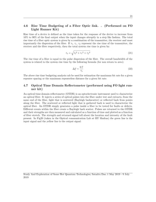
![22
Figure 20: The y-axis represents the power detected and the x-axis represents time for an OTDR
experiment observed at the Optical Communication Lab, EE Department, IIT Madras
4.8 Time division multiplexing (TDM) (using Benchmark’s Optical Fiber
Trainer kit)
This type of multiplexing is mostly used for digital signals and in this two or more signals are
transferred appearing simultaneously as sub-channels in one communication channel but are phys-
ically taking turns on the channel using the Optical Fiber Trainer. The use of multiple channels
allows increased overall data transmission capacities without increasing the data rates of the single
channels, or transmission of data of different users simultaneously. However, the time slot per bit
must be reduced.
Figure 21: Time division multiplexing[18]
4.9 Attenuation in Optical Fiber (Using the FO Light Runner Kit)
Although total internal reflection at the core-cladding interface is lossless, as the light rays propagate
through the fiber, they get attenuated because of various mechanisms such as absorption due to
impurities, scattering due to inhomogeneities in the core medium, imperfections at the core-cladding
Study And Exploration of Some Hot Quantum Technologies; Satadru Das; 1 May 2019 - 9 July
2019](https://image.slidesharecdn.com/internshipreport-190801134154/85/Summer-Internship-Report-2019-23-320.jpg)
![23
interface etc. Attenuation is given by the following relation:
Attenuation (A), in dB = −10log(Pout/Pin) (23)
Where Pin is the input power and Pout is the output power.
References
[1] Yoshihisa Yamamoto, Kazuyuki Aihara, Timothee Leleu, Ken-ichi Kawarabayashi, Satoshi
Kako, Martin Fejer, Kyo Inoue Hiroki Takesue Coherent Ising machines—optical neural net-
works operating at the quantum limit. -npj Quantum Information volume 3, Article number: 49
(2017)
[2] William R. Clements, Jelmer J. Renema, Y. Henry Wen, Helen M. Chrzanowski, W. Steven
Kolthammer, and Ian A. Walmsley - Gaussian optical Ising machines-Phys. Rev. A 96, 043850
– Published 23 October 2017
[3] HPE’s New Chip Marks a Milestone in Optical Computing-
(https://spectrum.ieee.org/semiconductors/processors/hpes-new-chip-marks-a-milestone-
in-optical-computing)
[4] Shashank Kumar Ranu ; Gautam Kumar Shaw ; Anil Prabhakar ; Prabha Mandayam -Security
with 3-Pulse Differential Phase Shift Quantum Key Distribution- IEEE(2017)
[5] Kyo Inoue, Member-Quantum Key Distribution Technologies-IEEE JOURNAL OF SELECTED
TOPICS IN QUANTUM ELECTRONICS, VOL. 12, NO. 4, JULY/AUGUST 2006
[6] S. Pirandola, U. L. Andersen, L. Banchi, M. Berta, D. Bunandar, R. Colbeck, D. Englund, T.
Gehring, C. Lupo, C. Ottaviani1, J. Pereira1, M. Razavi, J. S. Shaari, M. Tomamichel, V. C.
Usenko, G. Vallone, P. Villoresi, P. Wallden- Advances in Quantum Cryptography
[7] Nicolas Gisin, Gre´goire Ribordy, Wolfgang Tittel, and Hugo Zbinden- Quantum cryptography-
(https://cdn.journals.aps.org/files/RevModPhys.74.145.pdf)
[8] Ahmed I. Khaleel, Shelan Kh. Tawfeeq- Real Time Quantum Bit Error Rate Per-
formance Test for a Quantum Cryptography System Based on BB84 protocol -
(https://www.iasj.net/iasj?func=fulltextaId=45281)
[9] John Preskill-The security of quantum cryptography-(http://www.theory.caltech.edu/
preskill/talks/(Preskill Biedenharn2.pdf)
[10] Mavroeidis, Vasileios Vishi, Kamer Zych, Mateusz Jøsang, Audun. (2018). The Impact of
Quantum Computing on Present Cryptography. International Journal of Advanced Computer
Science and Applications. 9. 10.14569/IJACSA.2018.090354.
[11] Yasuhiro Tokura-Quantum Key Distribution Technology-NTT Review (https://www.ntt-
review.jp/archive/ntttechnical.php?contents=ntr201109fa6.pdfmode=show pdf)
[12] Mart Haitjema-A Survey of the Prominent Quantum Key Distribution Protocols-
(https://www.cse.wustl.edu/ jain/cse571-07/ftp/quantum/)
Study And Exploration of Some Hot Quantum Technologies; Satadru Das; 1 May 2019 - 9 July
2019](https://image.slidesharecdn.com/internshipreport-190801134154/85/Summer-Internship-Report-2019-24-320.jpg)
![24
[13] Guide to CWDM MUX/DEMUX System Installation-(http://www.chinacablesbuy.com/guide-
cwdm-muxdemux-system-installation.html?source=post page—————————)
[14] Fiber Bragg grating-(https://en.wikipedia.org/wiki/Fiber Bragg grating)
[15] Single Mode Fiber Optic Circulators-(https://www.thorlabs.com/newgrouppage9.cfm?objectgroup ID=373)
[16] Optical add-drop multiplexer-(https://en.wikipedia.org/wiki/Optical add-drop multiplexer)
[17] Fiber Optic Communication Lab Manual, IIT Madras
[18] Time Division Multiplexing-(https://www.rp-photonics.com/time division multiplexing.html)
Study And Exploration of Some Hot Quantum Technologies; Satadru Das; 1 May 2019 - 9 July
2019](https://image.slidesharecdn.com/internshipreport-190801134154/85/Summer-Internship-Report-2019-25-320.jpg)