The document discusses the detection of partial shading in photovoltaic (PV) panels, highlighting the impact of shading on efficiency and power generation. It proposes a methodology utilizing key points on the IV curve to identify mismatches in irradiance and enhance MPPT (Maximum Power Point Tracking) efficiency without the need for additional sensors. The approach aims to reduce implementation costs and improve performance in renewable energy systems.
Introduces the concept of partial shading in PV panels and the need for renewable energy due to climate concerns.
Discusses solar energy's advantages like eco-friendliness and availability, along with drawbacks such as intermittency and partial shading.
Explains the power curve of solar cells and the role of MPPT algorithms for optimal panel operation.
Details the impact of partial shading on solar panels, creating local hotspots, diminishing efficiency, and complicating MPPT’s ability to identify power peaks.
Reviews literature on methods to detect partial shading, emphasizing the need for thresholds in power and current measurements.
Presents a methodology for detecting partial shading using I-V curve analysis and mismatch calculation.
Describes how to detect uniform irradiance and discusses survey results on irradiance mismatch in PV modules.
Explains updating Voc during shading and outlines previous algorithm steps for enhancing partial shading detection.
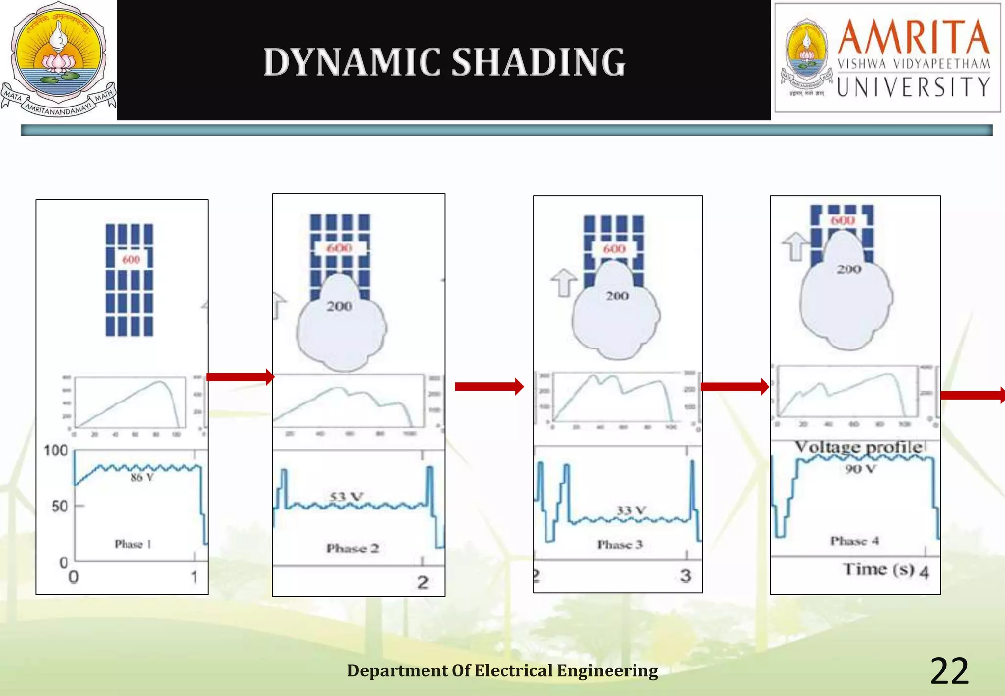
Discusses dynamic shading concepts and outlines advantages including improved efficiency and lower costs of MPPT implementation.
Concludes with a focus on the future of green energy, emphasizing sustainability and the importance of renewable energy solutions.
PARTIAL SHADING DETECTIONIN A PV
PANEL
DONE BY: ARUN PS
CB.EN.P2PWE17001
M-Tech PWE
ASE
Department Of Electrical Engineering 1
2.
INTRODUCTION
The IndustrialRevolution tapped full potential of fossil fuel energy
Limited availability of fossil fuels
Human activities have overloaded atmosphere with harmful gases.
It resulted in climate change and global warming.
Thus there was a need for a renewable source of energy which will
cause no environmental effects.
Department Of Electrical Engineering 2
3.
SOLAR ENERGY
Solarradiation is readily available- 300 sunny days per year
Eco friendly and less maintenance required as there are no moving
parts.
Can be used in remote locations
Modularity and silent generation of power
DRAWBACKS – intermittency
partial shading
Department Of Electrical Engineering 3
4.
POWER CURVE
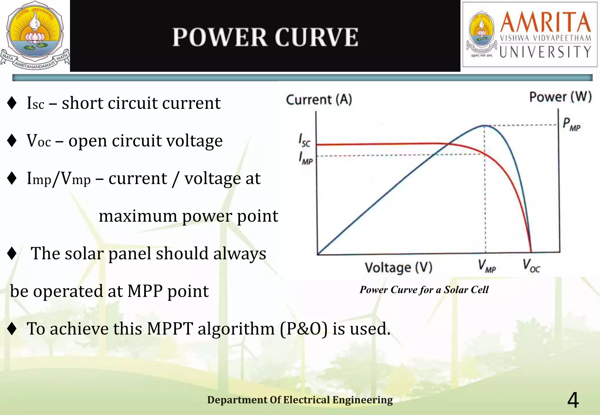
Isc– short circuit current
Voc – open circuit voltage
Imp/Vmp – current / voltage at
maximum power point
The solar panel should always
be operated at MPP point
To achieve this MPPT algorithm (P&O) is used.
Department Of Electrical Engineering 4
Power Curve for a Solar Cell
5.
MPPT
The MPPTalgorithm will ensure the operation of PV panel at MPP, when
there is a change in load
Department Of Electrical Engineering 5
6.
PARTIAL SHADING
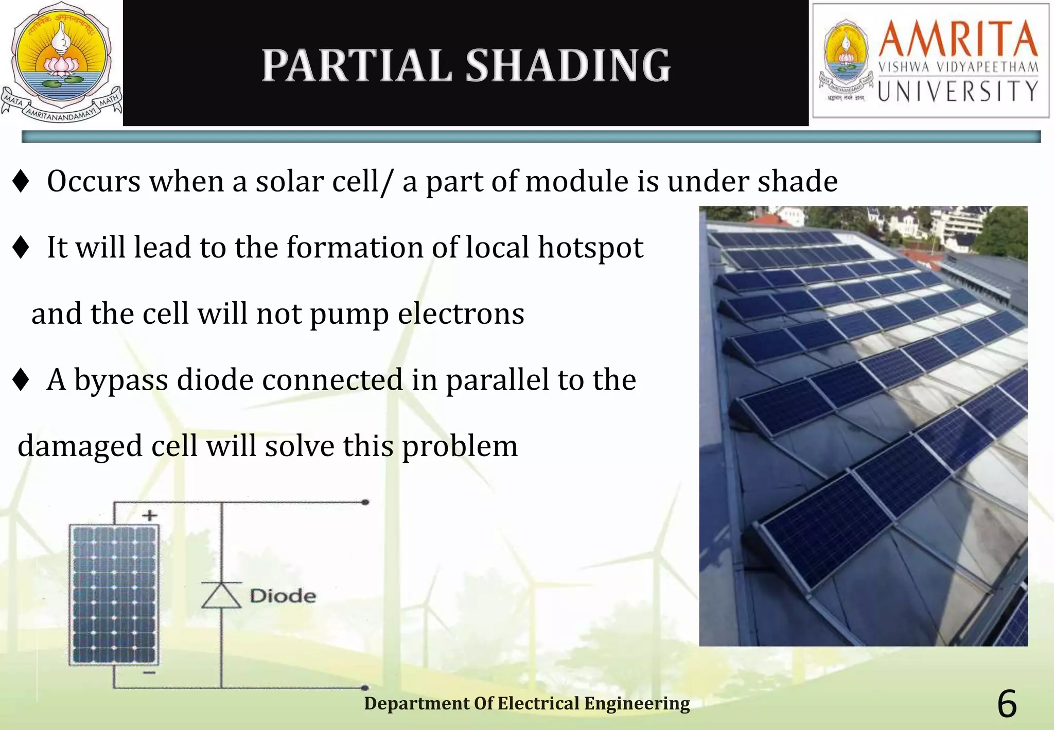
Occurswhen a solar cell/ a part of module is under shade
It will lead to the formation of local hotspot
and the cell will not pump electrons
A bypass diode connected in parallel to the
damaged cell will solve this problem
Department Of Electrical Engineering 6
7.
PARTIAL SHADING DETECTION??
DepartmentOf Electrical Engineering 7
VOLTAGE VOC
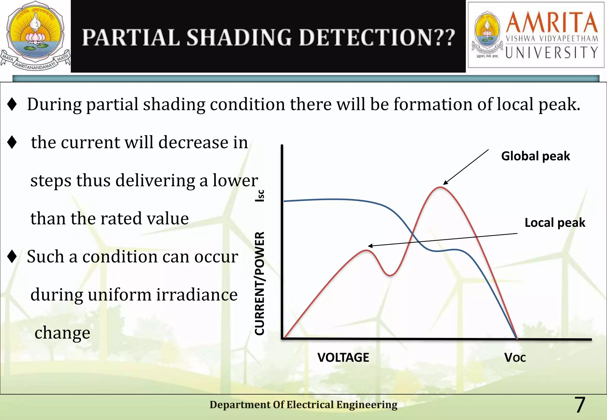
During partial shading condition there will be formation of local peak.
the current will decrease in
steps thus delivering a lower
than the rated value
Such a condition can occur
during uniform irradiance
change
CURRENT/POWERIsc
Global peak
Local peak
8.
EFFECT ON MPPT
Partial shading results in a multimodal PV curve with several peaks
The MPPT algorithm has to initiate a global peak search to extract
maximum power
MPPT cannot differentiate between partial shading and a uniform
irradiance change
As a result the MPPT will initiate a searching mechanism frequently
which will drop the efficiency of MPPT and the converter used.
Department Of Electrical Engineering 8
9.
HOW TO DETECTPARTIAL SHADING
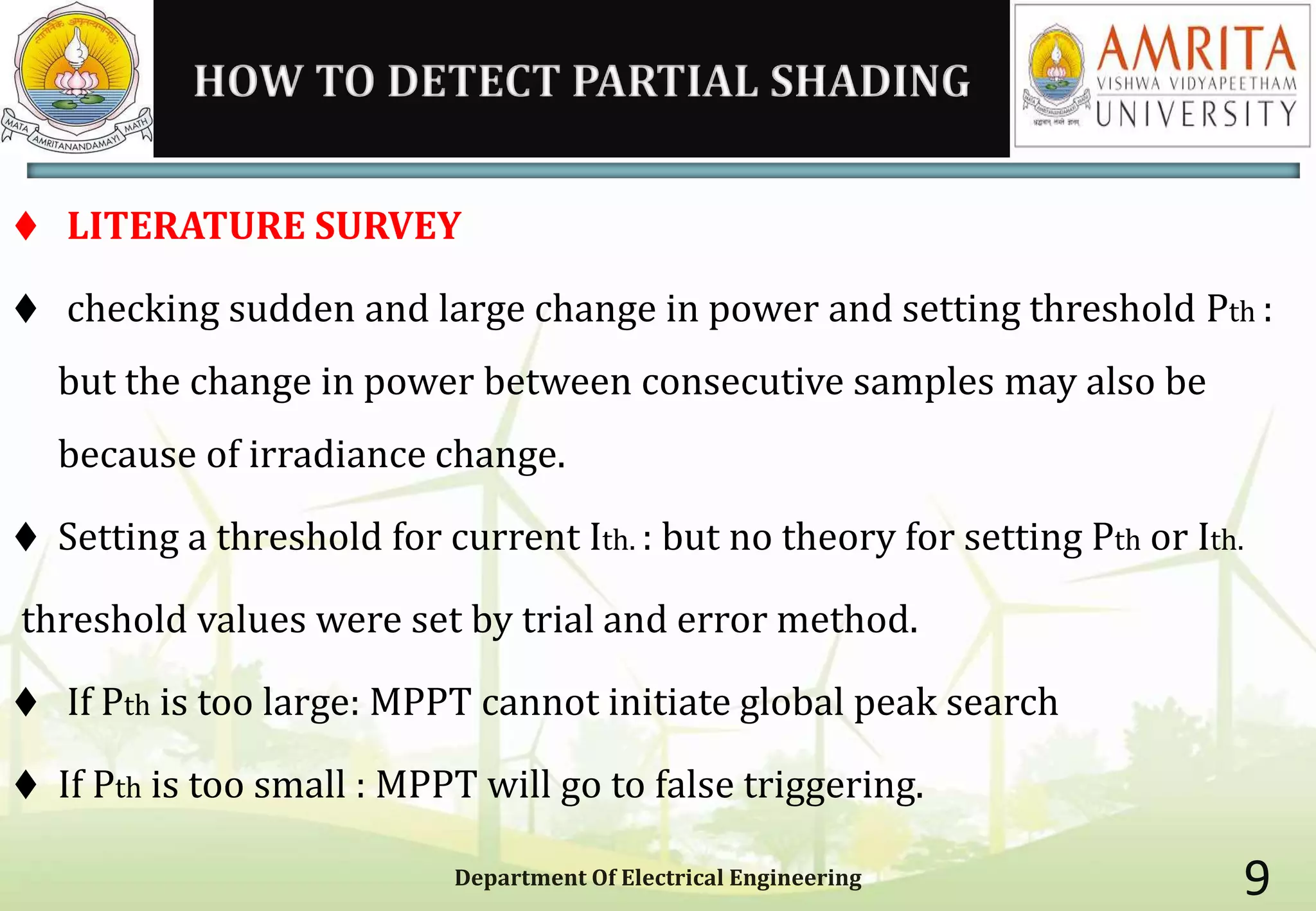
LITERATURE SURVEY
checking sudden and large change in power and setting threshold Pth :
but the change in power between consecutive samples may also be
because of irradiance change.
Setting a threshold for current Ith. : but no theory for setting Pth or Ith.
threshold values were set by trial and error method.
If Pth is too large: MPPT cannot initiate global peak search
If Pth is too small : MPPT will go to false triggering.
Department Of Electrical Engineering 9
10.
Literature survey contd…
By interpolation technique Pth was selected to be 15% or array capacity
Pth was set to be 0.1 – 0.2 PMPP
Pth was set to be 5% of nominal power.
Normalised deviation of power ⧍P/P was used as reference
All the above mentioned techniques does not have any theoretical support.
Detection of voltage mismatch in PV modules : but this will require a
voltage sensor in each module
Department Of Electrical Engineering 10
11.
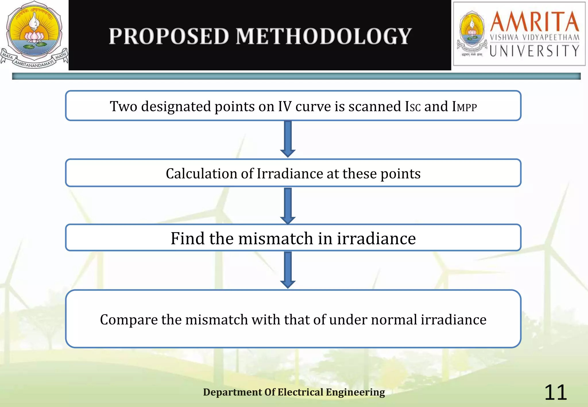
PROPOSED METHODOLOGY
Department OfElectrical Engineering 11
Two designated points on IV curve is scanned ISC and IMPP
Calculation of Irradiance at these points
Find the mismatch in irradiance
Compare the mismatch with that of under normal irradiance
12.
CONCEPT
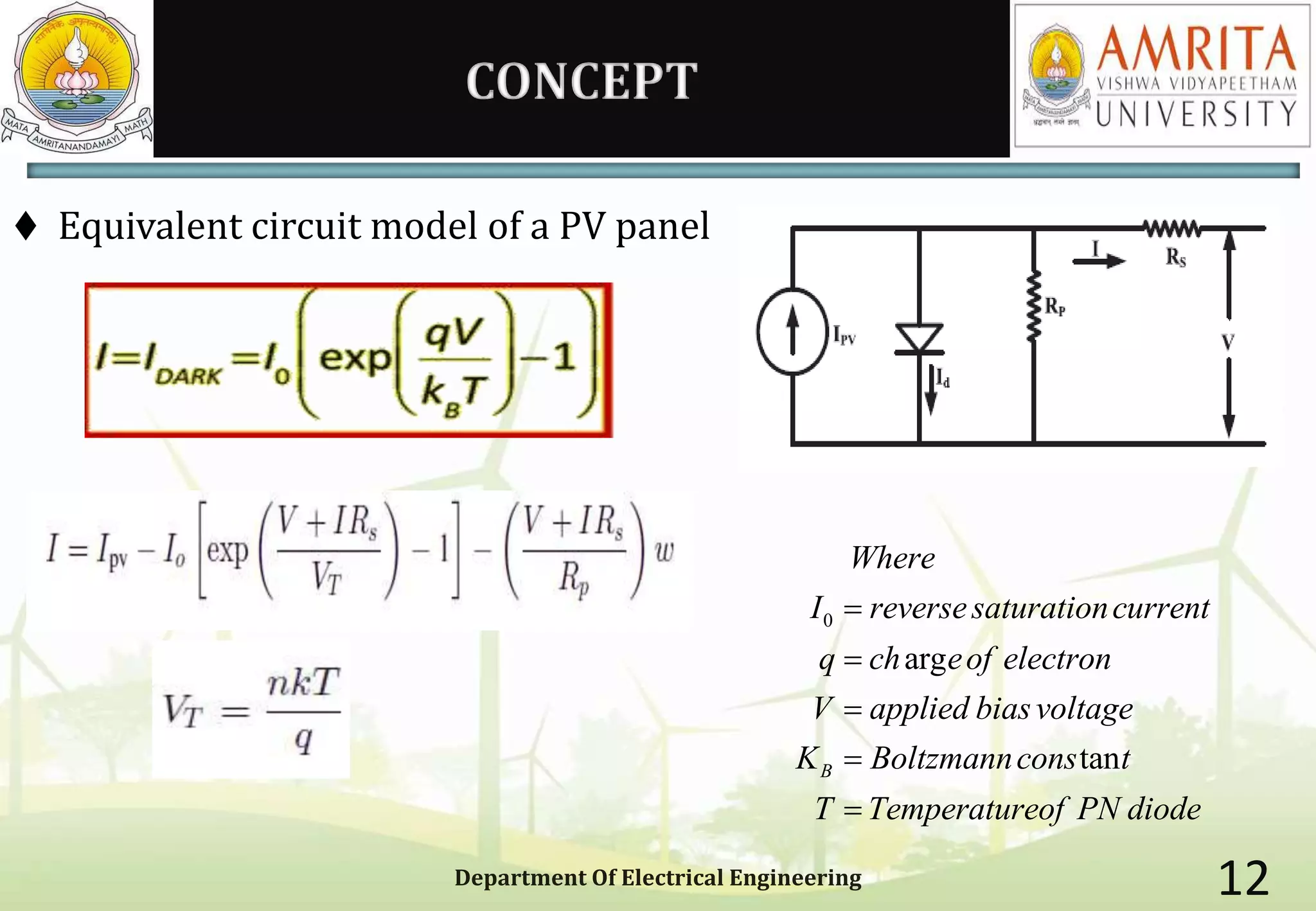
Equivalent circuitmodel of a PV panel
Department Of Electrical Engineering 12
0
arg
tanB
Where
I reversesaturationcurrent
q ch eof electron
V applied biasvoltage
K Boltzmanncons t
T Temperatureof PN diode
13.
CONTD..
Department Of ElectricalEngineering 13
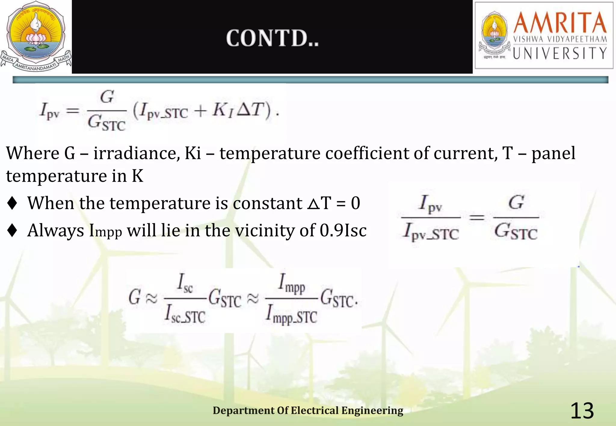
Where G – irradiance, Ki – temperature coefficient of current, T – panel
temperature in K
When the temperature is constant ⧍T = 0
Always Impp will lie in the vicinity of 0.9Isc
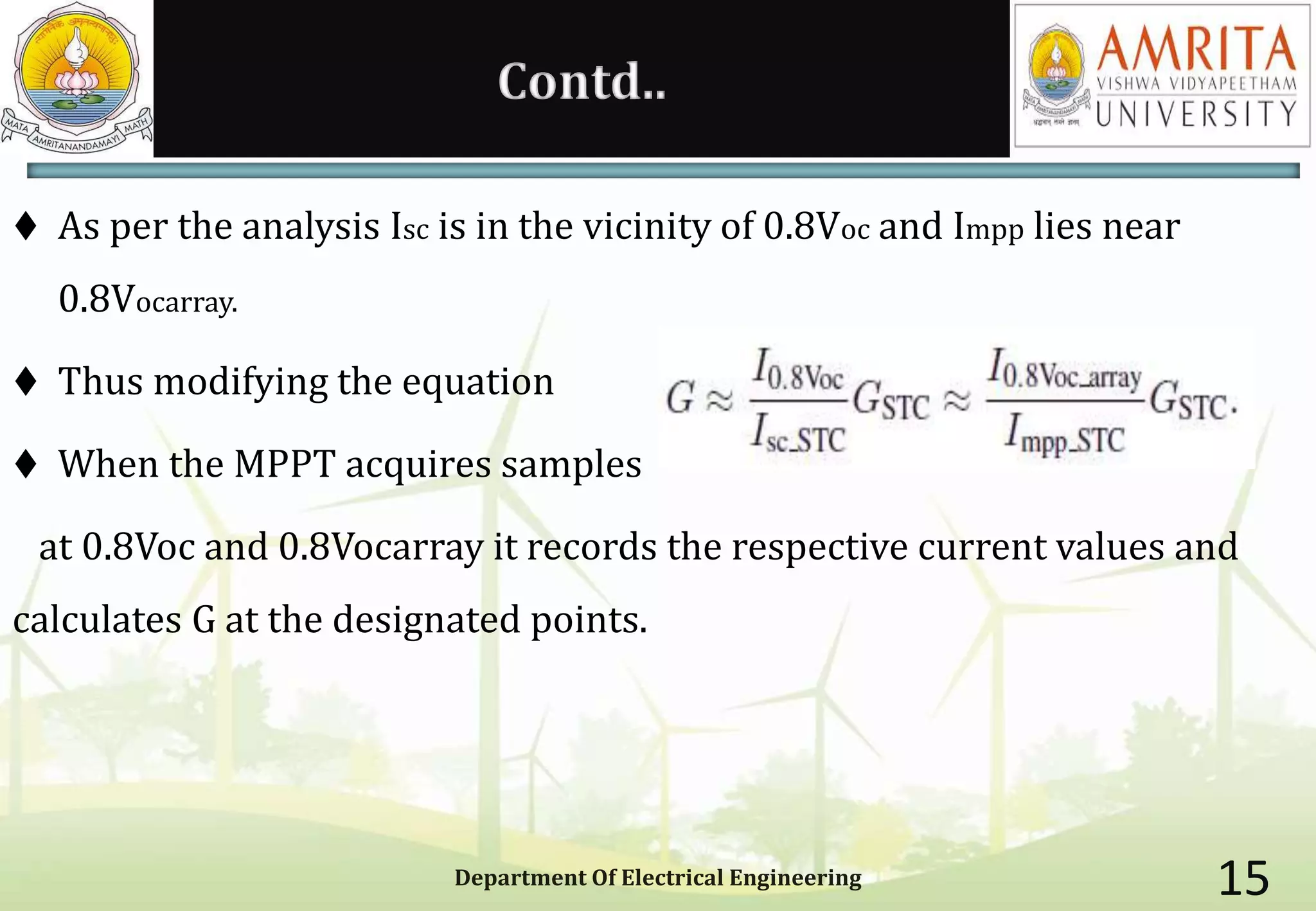
Contd..
As perthe analysis Isc is in the vicinity of 0.8Voc and Impp lies near
0.8Vocarray.
Thus modifying the equation
When the MPPT acquires samples
at 0.8Voc and 0.8Vocarray it records the respective current values and
calculates G at the designated points.
Department Of Electrical Engineering 15
16.
DETECTION OF UNIFORM
IRRADIANCE
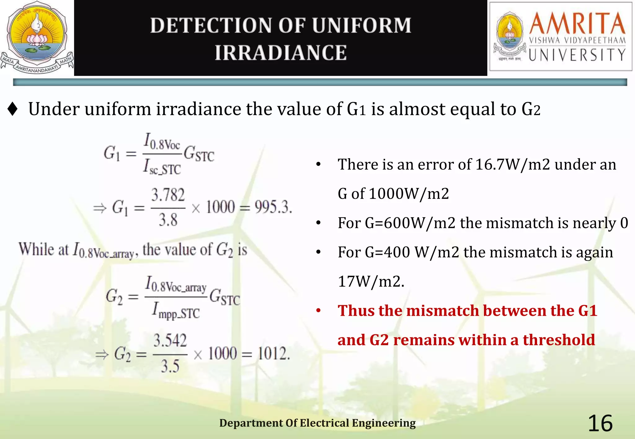
Under uniform irradiance the value of G1 is almost equal to G2
Department Of Electrical Engineering 16
• There is an error of 16.7W/m2 under an
G of 1000W/m2
• For G=600W/m2 the mismatch is nearly 0
• For G=400 W/m2 the mismatch is again
17W/m2.
• Thus the mismatch between the G1
and G2 remains within a threshold
17.
SURVEY TO FINDTHRESHOLD
To find the range of mismatch in G a survey was conducted for 10
monocrystalline and 10 polycrystaliine modules
Department Of Electrical Engineering 17
Thus in all the cases the
mismatch was found to be less
than 40W/m2
18.
UPDATING Voc
Vocis required to initialise the sample points,perturbation size and to
predict the local peak position
The effect of G on Voc will be less than effect of T. Here the computatioin
of Voc is through the value of G1 and G2
This is done in 2 steps
Department Of Electrical Engineering 18
19.
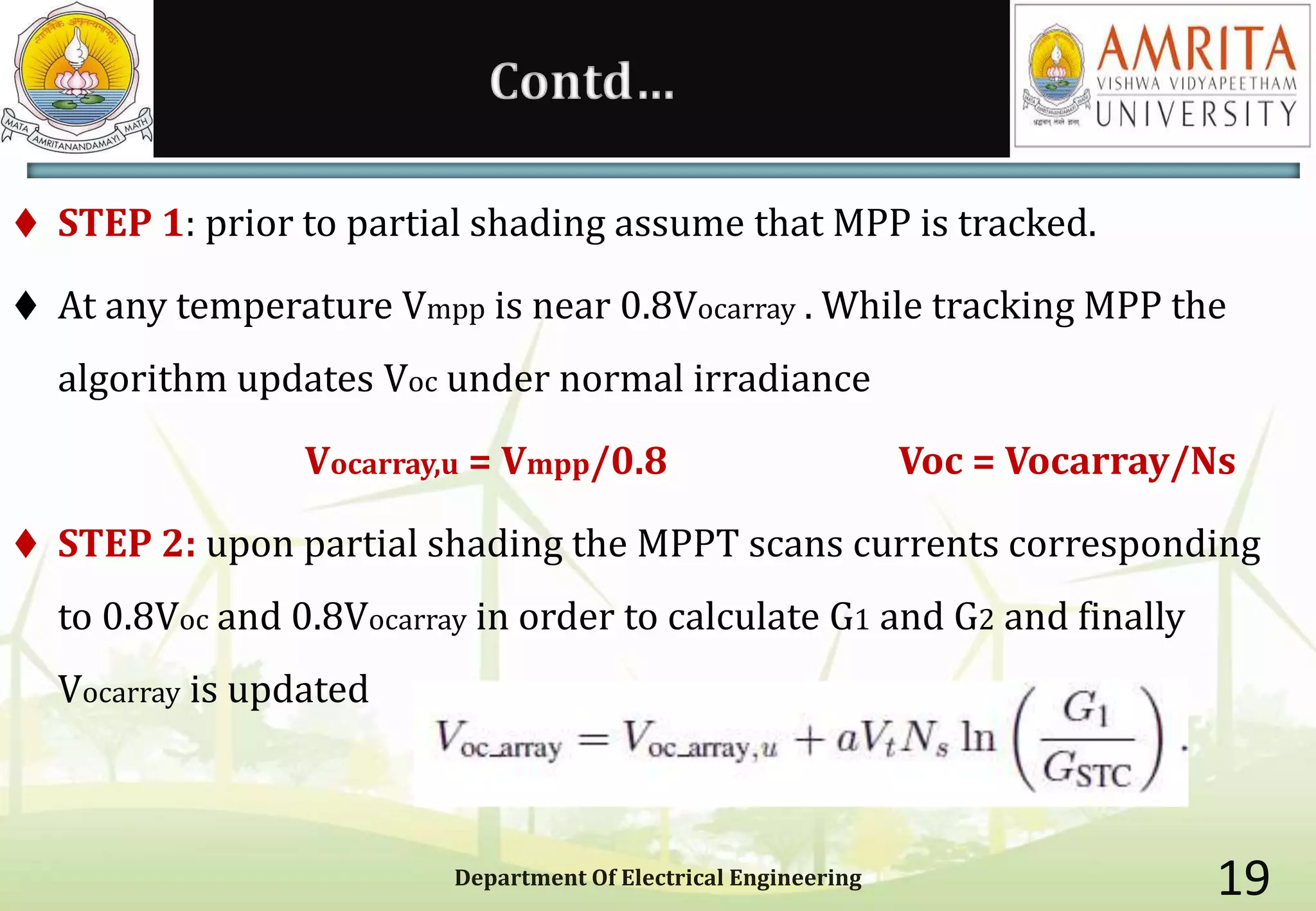
Contd…
STEP 1:prior to partial shading assume that MPP is tracked.
At any temperature Vmpp is near 0.8Vocarray . While tracking MPP the
algorithm updates Voc under normal irradiance
Vocarray,u = Vmpp/0.8 Voc = Vocarray/Ns
STEP 2: upon partial shading the MPPT scans currents corresponding
to 0.8Voc and 0.8Vocarray in order to calculate G1 and G2 and finally
Vocarray is updated
Department Of Electrical Engineering 19
ADVANTAGES
Increase inefficiency of MPPT and the converters
Temperature sensor or irradiance sensor not required as irradiance
value is used to update Voc
Less number of samples in MPPT – 3 samples. Thus increases the
transient efficiency.
Lower implementation costs
Versatile and adaptable
Prediction error is less than 3%
Department Of Electrical Engineering 24
25.
Department Of ElectricalEngineering 25
The future is green energy, sustainability and renewable energy