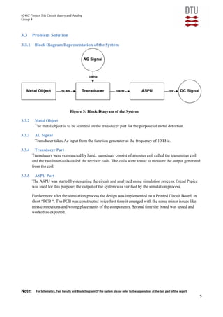
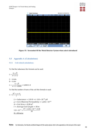
This report is documented for Metal Detector System. The goal is to analyze, design, model, simulate and construct the Metal Detector System. A very simple Design Pattern was used to modulate the system with the use of less number of components. Coils were designed in consideration to the principles of induction for the Metal Detector System. Standard components were used to construct the Signal Processing Unit (ASPU). The design for the ASPU was simulated and tested using advanced simulation software called Pspice. The final Product fulfills the requirements as expected.
This document describes the design and working of a low-cost metal detector circuit. It uses a Colpitts oscillator circuit with resistors, capacitors, transistors, diodes, an LED, coil, buzzer and battery. When the coil is brought near a metal object, it absorbs magnetic energy and causes the oscillator frequency to change. This triggers the final transistor to conduct, activating the buzzer and LED to indicate metal detection. The metal detector can be used to detect metallic objects for applications like food safety inspection and security systems.
Simple Metal Detector Circuit Diagram and Workingelprocus
A metal detector is used to sense any existing metal which is nearby. A Metal detector is an electronic device which is used in many places like theatres, shopping malls, hotels, etc., to detect any metallic objects like knives, guns or any other explosives kept hidden within.
This document provides an overview of an anti-sleep alarm circuit project. It includes a circuit diagram, descriptions of the main components used including an IC555 timer, relay, push button switch, buzzer, resistor, capacitor, transistor and diode. It describes the power supply, including the transformer, rectifier and filter. It explains how the circuit operates to sound an alarm after a set time interval if the push button is not pressed. The conclusion states that the circuit can be used to automatically switch home appliances on and off to save time and electricity.
this presentation tells about the vehicle controll by alcohole detector,where we have ellborately designed what is an alcohole detector,how it is made,and its application in the circuit when it leads to controlling of the vehicle.
This document describes the design and components of a simple metal detector circuit. It includes an introduction explaining how metal detectors work by detecting changes in a coil's magnetic field from nearby metals. The circuit uses a transistor as a Colpitts oscillator whose frequency shifts when metal is near the coil. Key components are listed along with explanations of their purpose and properties. Advantages of the simple design are portability and ability to detect metals, while limitations are low sensitivity and fixed capacitor values. Applications discussed include security screening and construction use to locate rebar or pipes.
This document describes how to build a robot that can be controlled via Bluetooth from a mobile phone or PC. An HC-05 Bluetooth module connects to a microcontroller on the robot to receive commands from a Bluetooth-enabled device. The microcontroller then uses a motor driver IC to control the robot's motors to move forward, reverse, or turn based on the received commands.
Automatic doorbell with object detectionAnurag Alaria
This document describes an automatic doorbell system that uses ultrasonic sensors to detect movement and ring a doorbell. It provides details on the components and circuit design of the transmitter and receiver modules that use ultrasonic waves to detect a person. The system is intended to automatically sense someone's presence and ring the doorbell, saving time and enhancing security compared to a traditional doorbell. The document includes circuit diagrams and descriptions of the main integrated circuits used, including the IC 555 timer and LM324 op-amp. It provides specifications and characteristics for the transistors and other components in the design.
Metal detectors operate using electromagnetic induction by transmitting a magnetic field and analyzing changes induced in metal objects. The document describes the principle of operation, including how eddy currents are induced in metals, opposing the magnetic field. It provides a circuit diagram and discusses the beat-frequency oscillator design. Metal detectors have applications in security screening, construction, civil engineering, landmine detection, and archaeology. They are compact, simple to use, and can detect small metal targets.
This document describes an automatic street light control circuit using an LDR (Light Dependent Resistor). The circuit uses an LM358 operational amplifier, a relay, an LDR, resistors, a capacitor, a transistor, and a lamp. It works by turning the street light on when the LDR detects low light levels and turning it off when high light levels are detected, thereby automatically controlling the street light and saving energy. The circuit was designed and simulated using Proteus software and implemented on a breadboard.
This document describes an obstacle avoiding car project created by Utkarsh Bingewar, Shubham Thakur, and Rupesh Rote, with guidance from their assistant professor Mrs. Varsha Nanaware. The car uses an ultrasonic sensor and Arduino board to detect obstacles and navigate around them. When an obstacle is detected, the Arduino controls the motors to turn the car left or right to avoid the obstacle. The obstacle avoiding car has applications in areas like surveillance, hazardous environments, and unmanned vehicle navigation.
AUTOMATIC PLANT WATERING SYSTEM USING ARDUINO BASED PPTrishav164
So what is this project? What does it do? Basically this is a soil moisture monitoring system, which detects if the moisture content in the soil is above or below a certain satisfactory threshold value. If it goes below a certain critical point, it is time to water the plant until the soil surrounding the plant is moist enough. An arrangement of a DC motor relay is used to control the watering mechanism.
INFRARED SENSOR WORKING PRINCIPLE AND CIRCUITKaushal Shah
This document summarizes an active learning assignment on infrared sensors. It introduces the topic, explaining that IR sensors are used to detect obstacles like human vision. It then describes the basic components of an IR sensor including the IR LED transmitter, photodiode receiver, and comparator circuitry. The document explains that the IR LED transmits light which bounces off objects and is detected by the photodiode, with the output compared to a reference voltage. Finally, it outlines some common applications of IR sensors and their pros and cons.
This document provides a design report for a smart street light system that aims to reduce energy wastage by automatically controlling street lights based on sunlight intensity and detecting movement. The system uses an Arduino microcontroller along with light dependent resistors and infrared proximity sensors to sense the environment and control street lamp brightness accordingly. It is designed to switch lights on when sunlight is low and increase brightness when motion is detected to save electricity without compromising visibility needs. The report outlines the objectives, design considerations, components, and challenges of implementing such a system.
This document presents a technical presentation on an automatic railway gate control system. The main aim of the project is to automate unmanned railway gates so that the gate closes automatically when a train approaches and opens after the train passes. It works using IR sensors to detect the train's approach and a microcontroller that controls stepper motors to open and close the gate. When a train is detected, the gate closes to prevent accidents at the railway crossing. This automatic system helps reduce accidents by removing human error.
This project report describes an obstacle avoiding robot created by a student group. The robot uses an ultrasonic sensor to detect obstacles in its path and a microcontroller to control two motors to navigate around obstacles. When the sensor detects an obstacle within 20cm, the microcontroller directs the robot to turn left. Otherwise, it moves straight. The report provides details on the robot's design, components, circuit diagram, algorithm, and testing process. It also discusses potential applications and future improvements.
This document describes an automatic street light control circuit using an LDR (light dependent resistor). The circuit uses an LDR, resistors, capacitors, diodes, a transistor and relay to automatically turn on LED street lights when it gets dark. When the LDR detects a drop in light levels, it causes the transistor to switch on, powering the relay and turning on the lights. The circuit requires few components, consumes little power and provides an efficient automatic method for controlling street lights without manual operation.
This course is electronics based course dealing with measurements and instrumentation designed for students in Physics Electronics, Electrical and Electronics Engineering and allied disciplines. It is a theory course based on the use of electrical and electronics instruments for measurements. The course deals with topics such as Principle of measurements, Errors, Accuracy, Units of measurements and electrical standards, , introduction to the design of electronic equipment’s for temperature, pressure, level, flow measurement, speed etc
This document describes an automatic engine locking system for drunken drivers using a microcontroller-based embedded system. The system uses an AT89S52 microcontroller, MQ-3 alcohol detection sensor, buzzer, LCD display, motors and other components. It aims to prevent accidents caused by drunk driving by locking the engine if the sensor detects alcohol on the driver's breath. The system has advantages like automation, safety and low power. Potential applications include use in vehicles and workplaces to detect alcohol consumption. Future enhancements could include GSM and GPS for location and notification.
Speed and direction control of dc motor using android mobile application grv ...chandan kumar
This project is all about the wireless operation of a DC Motor. In this project, we will control the speed of a DC Motor. Direction of the rotation will also be controlled. Wireless facility is provided with the help of Bluetooth connectivity. An android handset is required to control the operation. As the name suggests that “Speed and Direction Control of DC Motor using Android Mobile Application” is controlling the speed of a DC motor with any mobile phone containing some medium of connectivity such as Bluetooth
Water Level Indicator Project PresentationAbdul Rehman
This document presents a water level indicator circuit project. The circuit uses electrodes placed at different levels in a water tank connected to an Arduino. As the water level rises and makes contact with the electrodes, LEDs will light up to indicate the water level. Additionally, a buzzer will sound when the tank becomes full to provide an alarm. The document discusses the components used including electrodes, LEDs, resistors, transistors, buzzers, and a printed circuit board. It provides diagrams of the circuit and explanations of how each component works and is connected to indicate the water level and provide an alarm function.
Home Appliances Controlling using Android Mobile via BluetoothMOKTARI MOSTOFA
This project allows control of electrical appliances using an Android device. An Android application is installed to send commands via Bluetooth to a microcontroller. The microcontroller then controls relays connected to appliances like lights and fans, allowing remote switching on/off. This provides assistance for elderly and disabled people by making appliances controllable from a smartphone.
It is designed to measure the distance of any object by using an ultrasonic transducer. Ultrasonic means of distance measurement is a convenient method compared to traditional one using measurement scales.This kind of measurement is particularly applicable to inaccessible areas where traditional means cannot be implemented such as high temperature, pressure zones etc.
The document describes a proposed manhole monitoring system project that uses sensors and IoT technologies to monitor manholes in real-time. It aims to detect issues like accumulated sludge, drainage blockages, water levels, hazardous gas levels, and loss of manhole lids. The system will use sensors to collect data and send alerts to authorities via GSM if thresholds are exceeded. It will also apply machine learning to build predictive models for issues like gas formation.
3 phase Transmission Line fault detector edit 1-3.pptxKrishna2017
This document presents a project on an automatic tripping mechanism for a three-phase power supply system to prevent damage from faults. The system can detect line-to-ground, line-to-line, and other faults and automatically disconnect power. It uses an Arduino Uno microcontroller along with relays, sensors and other components to sense fault types, locations and temporarily or permanently trip the supply. The system provides safety benefits and can help reduce losses by quickly detecting and isolating faults on transmission lines, substations and industrial applications.
This document is an obstacle avoiding car project report submitted by three students - Utkarsh Bingewar, Shubham Thakur, and Rupesh Rote - to partially fulfill their project requirements for a bachelor's degree in electronics and telecommunications engineering. The report describes the design and implementation of a robotic vehicle that uses an ultrasonic sensor and microcontroller to detect and avoid obstacles in its path by controlling two DC motors through a motor driver. Experimental results show the car is able to successfully detect and navigate around obstacles.
Project: DC Power Supply(PCB)
Group Members:
Haris Abbas Qureshi 171000
M Zubair Khan 170907
M Ammar Aslam 170928
Department of Electrical and Computer Engineering . Air University,Islamabad
The project uses a PIR motion sensor to detect motion and trigger a camera. An Arduino microcontroller coordinates and controls the system, activating the camera when the PIR sensor detects motion.
Designed and manufactured an edge-coupled bandpass filter, with a required bandwidth of 900MHz at a center frequency of 3.8GHz experiencing 0.5dB pass-band ripple within Keysight ADS.
High performance novel dual stack gating technique for reduction of ground bo...eSAT Journals
Abstract The development of digital integrated circuits is challenged by higher power consumption. The combination of higher clock speeds, greater functional integration, and smaller process geometries has contributed to significant growth in power density. Today leakage power has become an increasingly important issue in processor hardware and software design. So to reduce the leakages in the circuit many low power strategies are identified and experiments are carried out. But the leakage due to ground connection to the active part of the circuit is very higher than all other leakages. As it is mainly due to the back EMF of the ground connection we are calling it as ground bounce noise. To reduce this noise, different methodologies are designed. In this paper, a number of critical considerations in the sleep transistor design and implementation includes header or footer switch selection, sleep transistor distribution choices and sleep transistor gate length, width and body bias optimization for area, leakage and efficiency. Novel dual stack technique is proposed that reduces not only the leakage power but also dynamic power. The previous techniques are summarized and compared with this new approach and comparison of both the techniques is done with the help of Digital Schematic( DSCH ) and Microwind low power tools. Stacking power gating technique has been analyzed and the conditions for the important design parameters (Minimum ground bounce noise) have been derived. The Monte-Carlo simulation is performed in Microwind to calculate the values of all the needed parameters for comparison. Index Terms: Ground Bounce Noise ,Power gating schemes ,Static power dissipation, Dynamic power dissipation, Power gating parameters, Sleep transistors, Novel dual stack approach, Transistor leakage power
IJRET : International Journal of Research in Engineering and Technology is an international peer reviewed, online journal published by eSAT Publishing House for the enhancement of research in various disciplines of Engineering and Technology. The aim and scope of the journal is to provide an academic medium and an important reference for the advancement and dissemination of research results that support high-level learning, teaching and research in the fields of Engineering and Technology. We bring together Scientists, Academician, Field Engineers, Scholars and Students of related fields of Engineering and Technology.
This thesis examines the performance of Space Shift Keying (SSK) modulation in Multiple Input Multiple Output (MIMO) wireless systems in the presence of co-channel interference. The author derives exact analytical expressions for the Average Bit Error Rate (ABER) of SSK modulation with co-channel interference and supports the analysis with MATLAB simulations. Performance is analyzed for systems with single and multiple receiving antennas over both correlated and uncorrelated Rayleigh fading channels, with and without co-channel interference.
This document describes the design and development of a laboratory model for a long transmission line. Key aspects include:
1) The model is based on scaled down parameters of an actual 351km, 375MVA, 400kV transmission line between Koradi and Bhushawal.
2) The line is represented by 7 pi sections, with each section modeling 50km. Components like inductors and capacitors were selected based on the scaled parameters.
3) Hardware implementation includes a control panel with instruments, contactors, and a PLC-SCADA system for online monitoring.
4) Both MATLAB simulation and hardware testing were done to observe the Ferranti effect voltage increase along the line. The model can
Laboratory Setup for Long Transmission LineIRJET Journal
This document describes the design and development of a laboratory model for a long transmission line. Key aspects include:
1) The model is based on scaled down parameters of an actual 351km, 375MVA, 400kV transmission line between Koradi and Bhushawal.
2) The line is represented by 7 pi sections, with each section modeling 50km. Components like inductors, capacitors, contactors, and meters were selected based on calculations.
3) Hardware implementation includes the physical construction of the model along with automation using PLC and SCADA for online monitoring.
4) Testing showed the model demonstrated phenomena like Ferranti effect similarly to the actual line. The model can be
This document is a project report submitted by a group of students for their Design Engineering course. It details the development of an Automatic Railway Crossing System (ARC) over multiple semesters. In the 6th semester, the students developed a PLC circuit board and program to control the ARC. They tested the circuit and program on a DELTA DVP-14SS2 PLC. The report provides snapshots of the PLC program and discusses modeling software, engineering economics, prototyping, materials selection, and future improvements including using renewable energy sources.
The document summarizes the design, analysis, and simulation of a Schottky diode-based sampling circuit for a 40 Gbps electronic time-division demultiplexer. The circuit uses a double diode configuration for sampling and undersampling theory to demultiplex the input signal. Bandwidth optimization is performed through analytic calculations and simulations. Layout design achieves 55 GHz bandwidth with a distance of 250 um between the capacitor and diode. Flip-chip bonding affects performance above 50 GHz. Future work includes using diodes with lower capacitance and compensating for flip-chip effects above 40 Gbps.
This document summarizes an engineering student's summer internship report on simulating and implementing a control system plant. The student:
1) Simulated the plant model in Proteus, PSpice and MATLAB, obtaining graphs of the system response.
2) Designed proportional and proportional-integral controllers in Simulink to achieve zero steady state error.
3) Implemented the open loop plant and closed loop system with controllers on hardware using an Arduino, resistors, capacitors, and op-amps.
This document describes a virtual lab for electronics that was created to address issues with limited hardware availability and large student-to-equipment ratios in university labs. The virtual lab allows students to design and simulate electronic circuits online through a web browser without needing to download any software. It includes models for common circuit components and can simulate circuits defined by the user. Analysis types like DC, transient, and AC can then be performed on the simulated circuits. Screenshots show an example circuit and output graph from the virtual lab. The goal is to help students learn circuit design and analysis through virtual experimentation before working with physical hardware.
This document describes the design and implementation of a controlled gain parabolic antenna. The system uses a microcontroller connected to an interface to control four stepper motors that adjust the position of four sectors of a parabolic reflector. This allows electronic control over the diameter of the reflector and thus the gain of the antenna. The document outlines the system components, hardware and software design, and algorithm for controlling the stepper motors to adjust each sector based on input from a keypad. In summary, the system provides programmatic control over a parabolic antenna's gain by allowing electronic adjustment of the reflector's diameter through four stepper motors.
The document describes the design and testing of a fast wire scanner project at TRIUMF including schematics and 3D models of the Galil controller box and motor driver box, details of the potentiometer circuit design, and results from testing the wire scanner at speeds up to 3.25m/s. The wire scanner is used to measure the profile of a high energy electron beam and includes stepper motors, potentiometers, and other electronics to move titanium wires across the beam at high speeds without melting. The author gained experience in electronics design, circuit testing, communication with other engineers, and learning new skills through hands-on work on the
This document describes a master's thesis project focused on sensorless speed and position estimation of a permanent magnet synchronous machine (PMSM). The project investigates sensorless control strategies using a back electromotive force (Back-EMF) method for position estimation and a phase-locked loop (PLL) for speed estimation. A field oriented control (FOC) system is designed to control the PMSM. The objectives are to propose bandwidths for different operating states, investigate angular position estimation errors, and compensate for magnetic saturation effects. Simulation and experimental results are presented to evaluate the sensorless control strategy.
• Sensorless speed and position estimation of a PMSM (Master´s Thesis)Cesar Hernaez Ojeda
Field Oriented Control (FOC) was chosen to control the motor. A Voltage Switch Inverter (VSI) controls the machine currents using Space Vector Modulation (SVM). Back-EMF method was used to estimate the position and a Phase Locked Loop to estimate the speed. The project was tested experimentally in the laboratory using a Danfoss power converter and dSpace.
IRJET- Low Power Adder and Multiplier Circuits Design Optimization in VLSIIRJET Journal
The document describes a proposed design for a low power 4-bit multiplier circuit using a hybrid full adder design with both pass-transistor logic and CMOS technology. The hybrid full adder uses 9 transistors compared to 12 in previous designs, reducing area and power. A faster Dadda algorithm is used to partition the partial product matrix into two parts that are reduced in parallel to two rows each using 3-bit and 2-bit counters, then combined with a carry look-ahead adder to form the final product. The proposed design aims to reduce propagation delay, power dissipation, and improve performance compared to previous multiplier circuit designs.
Design and Development of a Single Channel Analyzer with Microcontroller Base...IJAEMSJORNAL
Single Channel Analyzer (SCA) is a most common device used in today’s nuclear world. Therefore, A SCA with microcontroller based controlled output has been proposed in this article. The system comprises of Lower Level Discriminator (LLD), Upper Level Discriminator (ULD), wide dynamic range, Fast Processing and Hysteresis. The Comparator LM339N used as the key component that performs the main function of the proposed nuclear module. The multi-turn potentiometers have been used as LLD and ULD for the incoming linear pulses from shaping amplifier. The system has also employ the Hysteresis facilities so that oscillations due to stray feedback are not possible. A lower pin and less housing PIC microcontroller (P16F676) has been used to control the width and time delay of the output pulses.
The document summarizes Satadru Das' summer internship exploring quantum technologies at IIT Madras from May to July 2019. It discusses three approaches to building an optical Ising machine using optical parametric oscillators. It also covers several quantum key distribution protocols including BB84, DPS-QKD and E91. Finally, it describes experiments performed on fiber optic communication systems, including characterization of WDM components, fiber Bragg gratings, optical time domain reflectometry and more. The internship provided an opportunity for Satadru to learn about active research in quantum computing, communication and related fiber optic experiments.
Power System Stabilizer (PSS) for generatorKARAN TRIPATHI
This thesis examines damping of electromechanical oscillations in synchronous generators through power system stabilizers (PSS). It develops a PSS tuning methodology based on linear control theory and frequency response techniques. The thesis models a synchronous machine-infinite bus system to analyze system dynamics and tune the PSS. It also proposes an alternative damping controller based on signal estimation and evaluates its performance compared to PSS. The software tool developed implements the PSS tuning methodology.
Optimization of Threshold Voltage for 65nm PMOS Transistor using Silvaco TCAD...IOSR Journals
This document summarizes research optimizing the threshold voltage (VTH) for a 65nm PMOS transistor using Silvaco TCAD simulation tools. The researchers varied three fabrication factors - gate oxide thickness, channel doping concentration, and channel implantation concentration - in the simulation. The simulation results showed a VTH value of -2.55427V for a 65nm PMOS transistor with a gate oxide thickness of 0.0025um, boron channel doping of 2x10¹⁵, and phosphorus implantation of 3.5x10¹³ atom/cm-1. Thicker gate oxides, higher channel doping, and increased implantation concentrations each caused higher VTH values in the simulation, consistent with theoretical expectations.
This presentation for Metal Detector System. The goal is to analyze, design, model, simulate and construct the Metal Detector System. A very simple Design Pattern was used to modulate the system with the use of less number of components. Coils were designed in consideration to the principles of induction for the Metal Detector System. Standard components were used to construct the Signal Processing Unit (ASPU). The design for the ASPU was simulated and tested using advanced simulation software called Pspice. The final Product fulfills the requirements as expected.
Digital Communication and Modulation
Project 3 “Satellite Link Budgets and PE”
Arlene Meidahl - s107106 and Danish Bangash-s104712| Digital Communication | 21. maj 2015
Supervisor: John Aasted Sørensen
This document contains an analysis of eye diagrams and the Q-function for digital communication. It includes:
1) An explanation of how eye diagrams are generated and their purpose in analyzing communication systems. Eye diagrams provide an evaluation of signal-to-noise ratio, jitter, and other factors.
2) Code to generate eye diagrams using different bandwidths and an analysis of how bandwidth affects eye opening.
3) An explanation of the Q-function and its relationship to the normal probability density function, representing the probability of a value being above a threshold.
4) Scripts to plot the Q-function and illustrate its application in calculating bit error probability for digital transmission systems.
Finite Element Method Magnetics (FEMM) simulationDanish Bangash
Demonstration of a basic Finite Element Method Magnetics simulation program
*The demonstration is part of exam for FEMM course to operate a basic finite element simulation program took place at Denmark Technical University (2015).
The purpose of the Course DFM was to provide an overview of design for manufacturing techniques which is used to minimize the product cost through design and process improvements. It also describes and evaluates design of a new product from the prototype phase and until the mass production phase from applicable standards and regulations. And to calculate, estimate the lifetime of the electrical product, and to ensure the quality of an electric product through the production. The course leads us to explain different processes, optimum production flow based on cost, quality and high volume. This report will cover some of the major aspects, processes, and considerations for design for manufacturing.
The document describes an automated poker player system implemented in C# with six classes. The classes include Card, DeckOfCards, DrawCards, DealCards, HandEvaluator, and Program. Cards holds card values and suits. DeckOfCards populates a deck. DrawCards displays cards. DealCards deals cards and evaluates hands. HandEvaluator recognizes flushes, straights, and straight flushes. Program executes the system. The system deals cards, sorts hands, displays hands, and identifies winning hand types except royal flushes.
Bachelor- thesis, optimization of wireless power transfer coils using finite ...Danish Bangash
This document summarizes a student's final engineering project on optimizing wireless power transfer coils using finite element simulation. The student aims to investigate and increase the efficiency of inductive coils by optimizing their design using FEMM simulation software. Key steps include modeling coil designs in FEMM, verifying parameters in PSpice, performing mathematical calculations, and testing a practical coil model. Results show efficiency increases with frequency, with a maximum achieved. The student also explores hypotheses for multi-turn coil designs and their effects on efficiency. In conclusion, simulations, calculations, and practical testing supported optimizing coil design for wireless power transfer.
Redefining brain tumor segmentation: a cutting-edge convolutional neural netw...IJECEIAES
Medical image analysis has witnessed significant advancements with deep learning techniques. In the domain of brain tumor segmentation, the ability to
precisely delineate tumor boundaries from magnetic resonance imaging (MRI)
scans holds profound implications for diagnosis. This study presents an ensemble convolutional neural network (CNN) with transfer learning, integrating
the state-of-the-art Deeplabv3+ architecture with the ResNet18 backbone. The
model is rigorously trained and evaluated, exhibiting remarkable performance
metrics, including an impressive global accuracy of 99.286%, a high-class accuracy of 82.191%, a mean intersection over union (IoU) of 79.900%, a weighted
IoU of 98.620%, and a Boundary F1 (BF) score of 83.303%. Notably, a detailed comparative analysis with existing methods showcases the superiority of
our proposed model. These findings underscore the model’s competence in precise brain tumor localization, underscoring its potential to revolutionize medical
image analysis and enhance healthcare outcomes. This research paves the way
for future exploration and optimization of advanced CNN models in medical
imaging, emphasizing addressing false positives and resource efficiency.
The CBC machine is a common diagnostic tool used by doctors to measure a patient's red blood cell count, white blood cell count and platelet count. The machine uses a small sample of the patient's blood, which is then placed into special tubes and analyzed. The results of the analysis are then displayed on a screen for the doctor to review. The CBC machine is an important tool for diagnosing various conditions, such as anemia, infection and leukemia. It can also help to monitor a patient's response to treatment.
Batteries -Introduction – Types of Batteries – discharging and charging of battery - characteristics of battery –battery rating- various tests on battery- – Primary battery: silver button cell- Secondary battery :Ni-Cd battery-modern battery: lithium ion battery-maintenance of batteries-choices of batteries for electric vehicle applications.
Fuel Cells: Introduction- importance and classification of fuel cells - description, principle, components, applications of fuel cells: H2-O2 fuel cell, alkaline fuel cell, molten carbonate fuel cell and direct methanol fuel cells.
Embedded machine learning-based road conditions and driving behavior monitoringIJECEIAES
Car accident rates have increased in recent years, resulting in losses in human lives, properties, and other financial costs. An embedded machine learning-based system is developed to address this critical issue. The system can monitor road conditions, detect driving patterns, and identify aggressive driving behaviors. The system is based on neural networks trained on a comprehensive dataset of driving events, driving styles, and road conditions. The system effectively detects potential risks and helps mitigate the frequency and impact of accidents. The primary goal is to ensure the safety of drivers and vehicles. Collecting data involved gathering information on three key road events: normal street and normal drive, speed bumps, circular yellow speed bumps, and three aggressive driving actions: sudden start, sudden stop, and sudden entry. The gathered data is processed and analyzed using a machine learning system designed for limited power and memory devices. The developed system resulted in 91.9% accuracy, 93.6% precision, and 92% recall. The achieved inference time on an Arduino Nano 33 BLE Sense with a 32-bit CPU running at 64 MHz is 34 ms and requires 2.6 kB peak RAM and 139.9 kB program flash memory, making it suitable for resource-constrained embedded systems.
1. 62462 Project 3 in Circuit theory and Analog
Group 4
Metal
Detector
28. maj
2014
Abstract
This report is documented for Metal Detector System. The
goal is to analyze, design, model, simulate and construct
the Metal Detector System. A very simple Design Pattern
was used to modulate the system with the use of less
number of components. Coils were designed in
consideration to the principles of induction for the Metal
Detector System. Standard components were used to
construct the Signal Processing Unit (ASPU). The design
for the ASPU was simulated and tested using advanced
simulation software called Pspice. The final Product
fulfills the requirements as expected.
Supervisor
Abdallah Ahmad Ibrahim Al-Mass
Assistant Lecturer
DTU Ballerup Campus
aalm@dtu.dk
Lars Maack
Head of studies,
Associate professor
lmaa@dtu.dk
Students:
Danish Mohammed Ali Bangash - s104712
Arier Azad Jaff - s121635
Nobert Nikolas Kruz - s127648
2. 62462 Project 3 in Circuit theory and Analog
Group 4
Note: For Schematics, Test Results and Block Diagram Of the system please refer to the appendices at the last part of the report
1
Table of Contents
1 Introduction ............................................................................................................................................... 2
1.1 Project start........................................................................................................................................ 2
1.2 Problem Formulation......................................................................................................................... 2
1.3 Milestone Plan................................................................................................................................... 3
2 Problem Analysis....................................................................................................................................... 3
3 Project Delimitation and Methods............................................................................................................. 4
3.1 Solution Strategy ............................................................................................................................... 4
3.2 Requirements..................................................................................................................................... 4
3.3 Problem Solution............................................................................................................................... 5
3.3.1 Block Diagram Representation of the System........................................................................... 5
3.3.2 Metal Object .............................................................................................................................. 5
3.3.3 AC Signal .................................................................................................................................. 5
3.3.4 Transducer Part.......................................................................................................................... 5
3.3.5 ASPU Part ................................................................................................................................. 5
3.3.6 Transducer ................................................................................................................................. 6
3.3.7 Analog Signal Processing Unit (ASPU).................................................................................... 6
3.4 Resources (Hardware / Software)...................................................................................................... 9
4 Conclusion............................................................................................................................................... 10
4.1 Product Assessment......................................................................................................................... 10
4.2 Process Assessment......................................................................................................................... 10
5 Appendixes.............................................................................................................................................. 11
5.1 Appendix 1. (Schematics)................................................................................................................ 11
5.1.1 Amplifier ................................................................................................................................. 11
5.1.2 Active Full Wave Precision Rectifier...................................................................................... 11
5.1.3 Active Low Pass Filters In Cascade ........................................................................................ 12
5.1.4 Full System Schematic ............................................................................................................ 12
5.2 Appendix 2. (Transducer Test)........................................................................................................ 13
5.3 Appendix 3. (ASPU Tests).............................................................................................................. 14
5.4 Metal Detector Test ......................................................................................................................... 15
5.5 Appendix 4. (Calculations).............................................................................................................. 16
5.5.1 Coil related calculations: ......................................................................................................... 16
3. 62462 Project 3 in Circuit theory and Analog
Group 4
Note: For Schematics, Test Results and Block Diagram Of the system please refer to the appendices at the last part of the report
2
Preface
This report is fully packed with documentation of the metal detector system. It covers the important aspects
of the product and the process of developing the System.
The problem formulated is the combination of electro physics and circuit theory to implement the system
that can be used in real life as well.
The reader of the report should have the basic knowledge and understanding of the system or any related
theory.
1 Introduction
1.1 Project start
The goals for the project is to analyze design, construct, test and simulate a metal detector system. The
System should have to be able to detect any metal object under it but only metal.
It can be used for any security purposes at the airport or any metal restricted areas, many companies
require this product too for organic processes to evaluate the metal objects contained in any organic
processes like recycling and checking for metals.
1.2 Problem Formulation
For the metal detector there will be the need of a transducer, which operates with the input which is the coin
or metal object, the transducer is powered by the function generator, transducer consist of 3 coils, which
convey one energy domain to another energy domain. Transducer operates with the frequency of 10 kHz.
Copper wire is used for the construction of the coils.
An active precision rectifier has to be used to change the AC signal to a DC signal. The reason why the
rectifier should be active is that we amplify the signal; non-active rectifier has a voltage drop over the diodes.
An active low pass filter is used which are constructed using the OP-Amps with a reason to amplify the
signal as like the rectifier. However we are using two active low pass filters on of them makes the signal
smooth but reverse and the other does the same and have a high gain before the output.
And then the signal will be reversed by each other and generate an output of 5V DC with reduced noise and
smoothens the signal.
All the modules combined together will be the metal detector system.
4. 62462 Project 3 in Circuit theory and Analog
Group 4
Note: For Schematics, Test Results and Block Diagram Of the system please refer to the appendices at the last part of the report
3
1.3 Milestone Plan
Week Number
Task 12 13 14 15 16 17 18 19 20 21 22
Project Start x
Problem Formulation x
Block diagram x
Milestone Plan x
Create Transducer x
Testing Transducer x
Create ASPU x Holidays x
Testing ASPU holidays x
Simulations x
Adjustments x x
Error Correcting x x
Finish report x x
2 Problem Analysis
For the metal detector we will need a coil for detecting the metal part. Transducer consists of one transmitter
coil and two receiving. The transmitter coil is connected to a function generator. The receiving coils are
placed inside the transmitter coil, with each in the opposite direction of each other.
By placing the receiving coils in opposite directions of each other the B-field will be nullified by each other.
The small coil is connected to the ASPU, which gives the required output. Inside ASPU the AC signal gets
amplified, by the amplifier then the output is passed on to the rectification. A low pass filter is introduced in
order to ensure the output ripple is within the requirements.
5. 62462 Project 3 in Circuit theory and Analog
Group 4
Note: For Schematics, Test Results and Block Diagram Of the system please refer to the appendices at the last part of the report
4
3 Project Delimitation and Methods
3.1 Solution Strategy
A Precision Rectifier is used, also known as the Full Wave Precision Rectifier the topology used is based on
two stages, HWR and a summing stage. Two Low Pass Filters are constructed in cascade to filter the
rectified signal the designed is properly calculated and simulated with respect to the preset requirements.
For the purpose of the induction, outer coil called the transmitter coils was mounted on the top of the plastic
plate and the inner coils called the receiver coils are placed precisely measured as fitted inside the transmitter
coils.
3.2 Requirements
Here we have specified the requirements for the metal detector.
System requirements:
Reference Test Object: A Danish “5 KRONER” coin
Reference Position: Test Object is 1 cm from the transducer at the place, and an orientation, where
the sensitivity is best.
Output DC voltage when the Reference Test Object is at its reference position: VOUT = 5 V ± 0.5 V
Output DC voltage with no metal object: VOUT = 0 V ± 0.5 V
Output peak to peak ripple voltage: Vout peak-to-peak ≤ 20 mV
Transducer requirements:
The transducer must be of type “Continuous Wave - Differential coil” operating at 10 kHz
The transducer output voltage must be zero initially and as big as possible when metal is nearby.
The transducer must be driven from a standard lab function generator with 50 ohm output resistance.
The transducer must have a flat physical design and be homemade. You must decide the number of
turns, size and geometries.
The design should be explained from electro physics formulas and sketches or simulations of the
magnetic fields
Analog Signal Processing Unit (ASPU) requirements:
The ASPU must convert the transducer output signal into a system output voltage as specified under
“System Requirements”
The transducer may pick up unwanted external noise in a broad frequency range. To reduce this
noise, the transducer + ASPU input stages, must have a 3-dB bandwidth of maximum 4 kHz
Additional requirements:
Potentiometers or variable resistors are in general unwanted, but if needed it can be accepted for fine
tuning the output voltage e.g. for sensitivity adjustment
6. 62462 Project 3 in Circuit theory and Analog
Group 4
Note: For Schematics, Test Results and Block Diagram Of the system please refer to the appendices at the last part of the report
5
3.3 Problem Solution
3.3.1 Block Diagram Representation of the System
Figure 5: Block Diagram of the System
3.3.2 Metal Object
The metal object is to be scanned on the transducer part for the purpose of metal detection.
3.3.3 AC Signal
Transducer takes Ac input from the function generator at the frequency of 10 kHz.
3.3.4 Transducer Part
Transducers were constructed by hand, transducer consist of an outer coil called the transmitter coil
and the two inner coils called the receiver coils. The coils were tested to measure the output generated
from the coil.
3.3.5 ASPU Part
The ASPU was started by designing the circuit and analyzed using simulation process, Orcad Pspice
was used for this purpose; the output of the system was verified by the simulation process.
Furthermore after the simulation process the design was implemented on a Printed Circuit Board, in
short “PCB “. The PCB was constructed twice first time it emerged with the some minor issues like
miss connections and wrong placements of the components. Second time the board was tested and
worked as expected.
7. 62462 Project 3 in Circuit theory and Analog
Group 4
Note: For Schematics, Test Results and Block Diagram Of the system please refer to the appendices at the last part of the report
6
3.3.6 Transducer
The transceiver coil generates a B-field by the 10 kHz alternating current signal form the function generator.
The two inner coils in the system are a transmitter coil and receiver coil. The inner coils will counter the B -
field with a B - field from the induced current.
This will lead to an induced current and voltage:
( )
( )
These formulas are defined by Faraday's law of electromagnetic induction.
Both inner coils will create a B - field. The B - field of the receiving coil will be opposing the B - field of the
transmitter coil due to their turning in opposite directions. It is important to design these two receiver coils of
same size and turns so that they nullify each other when there is no coin.
By holding a coin over the receiving coil a drop in voltage happens, since adding an extra B - field will
reduce the voltage.
This will lead to detection of the coin.
3.3.7 Analog Signal Processing Unit (ASPU)
3.3.7.1 Amplifier
The operational amplifier is connected with feedback to produce a closed loop operation. The
inverting amplifier circuit amplifies a voltage by a factor –R2/R1.So that the gain of the circuit can
be controlled by controlling the resistor value.
Figure 1: Screenshot of the amplified signal
8. 62462 Project 3 in Circuit theory and Analog
Group 4
Note: For Schematics, Test Results and Block Diagram Of the system please refer to the appendices at the last part of the report
7
3.3.7.2 Full Wave Precision Rectifier
In order to make the signal a positive DC signal a decision was taken to use a precision rectifier. The
precision rectifier, also known as the super diode, configuration obtained with an operational amplifier
in order to have circuit behave like an ideal diode and rectifier which are useful for high-precision
signal processing.
The rectifier is divided in two parts first part of the circuit is active when the signal is positive, for
each half cycle, one diode is forward biased, and the other is reversed biased.
The output of the first part generates a Half Wave Rectification with negative value of the double
positive input value which is added to a sine wave as an input to the second part of the Precision
Rectifier. It generates a Full Wave Rectification at the output with the negative value furthermore the
signal is added to the inverting OP-Amp and a positive full wave signal is generated.
Figure 2: Simulation shot of full wave rectification in Time Domain.
3.3.7.3 Active low Pass Filters
The use of two filters was needed to average the average of the rectified signal- the pulsating DC. The
purposed component is called cascaded active low pass filters.
The basic RC circuit principle is used for implantation of the circuit for filters. The resistor has a
constant resistance while the capacitor varies its impedance. High resistance is optimized at a very low
frequencies and a very low resistance optimized at higher frequencies.
The Filters are acting as a voltage divider,
We need to find out R=XC=10k which is the cut off frequency at -3db, is calculated using the
equation given below
9. 62462 Project 3 in Circuit theory and Analog
Group 4
Note: For Schematics, Test Results and Block Diagram Of the system please refer to the appendices at the last part of the report
8
Gain of Op-Amp Av =
Capacitor value calculated using C =
Resistance calculated using R2 =
Transfer Function for the filters
In figure below we can see the bode plot of the two low pass filters in cascade. Since the cutoff
frequency for both filters is the same, we have two poles laying at the cutoff frequency
Figure 3: Screenshot of active low pass filters in Frequency Domain
The poles Y1 and Y2 are laying at value of 41.147 DB
The Cutoff frequency is laying at 106 Hz approx. -6db. Raise time is of approx. 5ms (see figure 4).
10. 62462 Project 3 in Circuit theory and Analog
Group 4
Note: For Schematics, Test Results and Block Diagram Of the system please refer to the appendices at the last part of the report
9
Figure 4: Screenshot of active low pass filters in Time Domain
Raise time is approx. 5ms as show in the figure above marked with white line defined as 10% - 90% of the steady
state value in our case it’s the 5V
3.4 Resources (Hardware / Software)
Orcad Pspice was used to design and simulate the circuit decided for the ASPU of the Metal Detector
System.
Use of Function Generator was required to generate 10 KHz signal.
Power Supply was used to power up the Operational amplifiers at the required input voltage.
Standard Lab Oscilloscope was used to test the product and compare the simulation results with
measurements.
Standard tool box was used which contained cables for various machines.
Help from the supervisor was accessed whenever needed.
http://daycounter.com/Articles/How-To-Measure-Inductance.phtml
http://www.electronics-tutorials.ws/inductor/inductance.html
11. 62462 Project 3 in Circuit theory and Analog
Group 4
Note: For Schematics, Test Results and Block Diagram Of the system please refer to the appendices at the last part of the report
10
4 Conclusion
Part Requirement Nr Description Mandatory / Optional State
System
R1 Test object: 5 crowns Mandatory Approved
R2 Testing distance: 1 cm Mandatory Approved
R3 Max output: 4.5 V - 5.5V Mandatory Approved
R4 Min output: 0 V - 0.5 V Mandatory Approved
R5 Peak to peak: <20 mV Mandatory Approved
Transducer
R6 Operating value: 10 kHz Mandatory Approved
R7 Min output: ~ 0
Max output: 0 <
Mandatory Approved
R8 Use of function generator Mandatory Approved
R9 Handmade & calculations Mandatory Approved
R10 Formulas Mandatory Approved
ASPU R11 Convert signal Mandatory Approved
R12 3-dB bandwidth of max. 4 kHz Mandatory Approved
Additional R13 Use of potentiometers or variable
resistors
Optional Rejected
4.1 Product Assessment
The product ended up by fulfilling the expected requirements. Some of the major requirements are the
rise and fall time, +-0,5v 5v output. Approximately zero at the input when no coin is available.
The Image at the start page is the final prototype of the Metal Detector System.
4.2 Process Assessment
It is always convenient to work with such a well-defined project who’s learning outcome is at its peak
.It is always best to particulate according to the aspects of theory. We worked according to our time
plan therefore we did not emerged with any major problems everything went very clearly though we
had some issues but not any serious technical issues. Group work was outstanding gave us a good
communication skills and understanding others work. Problem was modulated and was fairly fulfilled
by the group members.
12. 62462 Project 3 in Circuit theory and Analog
Group 4
Note: For Schematics, Test Results and Block Diagram Of the system please refer to the appendices at the last part of the report
11
5 Appendixes
5.1 Appendix 1. (Schematics)
5.1.1 Amplifier
Figure 5: Screen Shot shows the Amplification Circuit
5.1.2 Active Full Wave Precision Rectifier
13. 62462 Project 3 in Circuit theory and Analog
Group 4
Note: For Schematics, Test Results and Block Diagram Of the system please refer to the appendices at the last part of the report
12
Figure 6: Screen Shot shows the Full Wave Rectifier (active)
5.1.3 Active Low Pass Filters In Cascade
Figure 7: Screen Shot shows the Low Pass Filters in Cascade
5.1.4 Full System Schematic
Figure 8: Screen Shot shows the Schematic of the Whole System
14. 62462 Project 3 in Circuit theory and Analog
Group 4
Note: For Schematics, Test Results and Block Diagram Of the system please refer to the appendices at the last part of the report
13
5.2 Appendix 2. (Transducer Test)
Figure 9: Screenshot of transducer test when no coin in there
Figure 10: Screenshot of the transducer test when coin is introduced
15. 62462 Project 3 in Circuit theory and Analog
Group 4
Note: For Schematics, Test Results and Block Diagram Of the system please refer to the appendices at the last part of the report
14
5.3 Appendix 3. (ASPU Tests)
Figure 11: Screenshot of the Amplification test
Figure 12: Screenshot of the half wave rectification test
16. 62462 Project 3 in Circuit theory and Analog
Group 4
Note: For Schematics, Test Results and Block Diagram Of the system please refer to the appendices at the last part of the report
15
Figure 13: Screenshot of the full wave rectification test
5.4 Metal Detector Test
Figure 14: Screenshot of Metal Detector when idle
17. 62462 Project 3 in Circuit theory and Analog
Group 4
Note: For Schematics, Test Results and Block Diagram Of the system please refer to the appendices at the last part of the report
16
Figure 15: Screenshot Of the Metal Detector System when coin is introduced
5.5 Appendix 4. (Calculations)
5.5.1 Coil related calculations:
To find the inductance this formula can be used:
√
F = 10 kHz
R = 4 ohm
√
To find the number of turns of the coil this formula is used:
( )
18. 62462 Project 3 in Circuit theory and Analog
Group 4
Note: For Schematics, Test Results and Block Diagram Of the system please refer to the appendices at the last part of the report
17