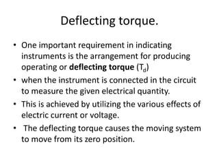
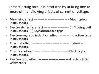
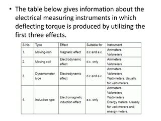
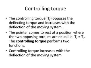
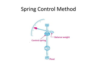
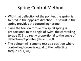
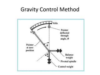
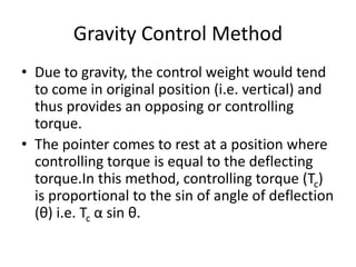
Basic requirements of electrical
instruments
Unit 5
Basic requirements of electrical
instruments
• In order to ensure proper operation of
indicating instruments, the following three
torques are required:
• Deflecting torque.
• Controlling torque.
• Damping torque.
Deflecting torque.
• One important requirement in indicating
instruments is the arrangement for producing
operating or deflecting torque (Td)
• when the instrument is connected in the circuit
to measure the given electrical quantity.
• This is achieved by utilizing the various effects of
electric current or voltage.
• The deflecting torque causes the moving system
to move from its zero position.
• Magnetic effect ——————————- Moving-iron
instruments.
• Electro dynamic effect ———————- (i) Moving coil
instruments, (ii) Dynamometer type.
• Electromagnetic induction effect ———Induction type
instruments.
• Thermal effect ———————————Hot-wire
instruments.
• Chemical effect ——————————–Electrolytic
instruments.
• Electrostatic effect —————————-Electrostatic
voltmeters
The deflecting torque is produced by utilizing one or
more of the following effects of current or voltage:
• The table below gives information about the
electrical measuring instruments in which
deflecting torque is produced by utilizing the
first three effects.
Controlling torque
• The controlling torque (Tc) opposes the
deflecting torque and increases with the
deflection of the moving system.
• The pointer comes to rest at a position where
the two opposing torques are equal i.e. Td = Tc.
The controlling torque performs two
functions.
• Controlling torque increases with the
deflection of the moving system
Controlling torque
• so that the final position of the pointer on the
scale will be according to the magnitude of an
electrical quantity (i.e. current or voltage or
power) to be measured.
• Controlling torque brings the pointer back to
zero when the deflecting torque is removed.
• If it were not provided, the pointer once
deflected would not return to zero position on
removing the deflecting torque
Controlling torque
• The controlling torque in indicating
instruments may be provided by one of the
following two methods:
• Spring control.
• Gravity control.
Spring Control Method
• This is the most common method of providing
controlling torque, in electrical instruments.
• A spiral hairspring made of some non-
magnetic material like phosphor bronze is
attached to the moving system of the
instrument as shown in the figure .
• Springs also serve the additional purpose of
leading current to the moving system (i.e.
operating coil).
Spring Control Method
• With that deflection of the pointer, the spring is
twisted in the opposite direction. This twist in the
spring provides the controlling torque.
• Since the torsion torque of a spiral spring is
proportional to the angle of twist, the controlling
torque (Tc ) is directly proportional to the angle of
deflection of pointer (θ) i.e. Tc α θ.
• The pointer will come to rest at a position where
controlling torque is equal to the deflecting
torque i.e. Td =Tc.
Spring Control Method
• In an instrument where the deflecting torque
is uniform, spring control provides a uniform
scale over the whole range.
• The balance weight is attached to
counterbalance the weight of the pointer and
other moving parts.
Gravity Control Method
• In this method, a small weight is attached to the
moving system, which provides necessary
controlling torque.
• In the zero position of the pointer, the control
weight hangs vertically downward and therefore
provides no controlling torque.
• However, under the action of deflecting torque,
the pointer moves from zero position and control
weight moves in opposite direction.
Gravity Control Method
• Due to gravity, the control weight would tend
to come in original position (i.e. vertical) and
thus provides an opposing or controlling
torque.
• The pointer comes to rest at a position where
controlling torque is equal to the deflecting
torque.In this method, controlling torque (Tc)
is proportional to the sin of angle of deflection
(θ) i.e. Tc α sin θ.
Gravity Control Method
• Because in this method controlling torque (Tc)
is not directly proportional to the angle of
deflection (θ) but it is proportional to sin θ
therefore, gravity control instruments have
non-uniform scales; being crowded in
beginning.
Damping torque
• A damping torque is produced by a damping or
stopping force which acts on the moving system
only when it is moving and always opposes its
motion.
• Such a torque is necessary to bring the pointer to
rest quickly. If there is no damping torque, then
the pointer will keep moving to and fro about its
final deflected position for some time before
coming to rest, due to the inertia of the moving
system.
Damping torque
• This damping torque acts only when the pointer
is in motion and always opposes the motion.
• The position of the pointer when stationary is,
therefore, not affected by damping torque.
• The degree of damping decides the behavior of
the moving system. If the instrument is under-
damped, the pointer will oscillate about the final
position for some time before coming to rest.
• On the other hand, if the instrument is over
damped, the pointer will become slow and
lethargic.
Damping torque
• However, if the degree of damping is adjusted to
such a value that the pointer comes up to the
correct reading quickly without oscillating about
it, the instrument is said to be critically damped.
Types of Damping Torque
• The damping torque in indicating instruments can
be provided by:
• Air friction damping.
• Fluid friction damping.
• Eddy current damping.
Air Friction Damping
• Arrangements of air friction damping are
shown in fig. (a) and fig. (b). In the
arrangement shown in fig (a),
• A light aluminum piston is attached to the
spindle that carries the pointer and moves
with a very little clearance in a rectangular or
circular air chamber closed at one end.
Air Friction Damping
• The cushioning action of the air on the piston
damps out any tendency of the pointer to
oscillate about the final deflected position.
• This method is not favored these days and the
one shown in fig. (b) is preferred.
• In this method, one or two light aluminum
vanes are attached to the same spindle that
carries the pointer.
Air Friction Damping
• As the pointer moves, the vanes swing and
compress the air.
• The pressure of compressed air on the vanes
provides the necessary damping force to
reduce the tendency of the pointer to
oscillate.
Fluid Friction Damping
• In this method, discs or vanes attached to the
spindle of the moving system are kept immersed
in a pot containing oil of high viscosity.
• As the pointer moves, the friction between the oil
and vanes opposes the motion of the pointer and
thus necessary damping is provided.
• The fluid friction damping method is not suitable
for portable instruments because of the oil
contained in the instrument.
Eddy Current Damping
• Two methods of eddy current damping are
generally used . In the first method, as shown in
the figure,
• A thin aluminum or copper disc is attached to the
moving system is allowed to pass between the
poles of a permanent magnet.
• As the pointer moves, the disc cuts across the
magnetic field and eddy currents are induced in
the disc.
Eddy Current Damping
• These eddy currents react with the field of the
magnet to produce a force which opposes the
motion according to Lenz’s Law.
• In this way, eddy current damping torque reduces
the oscillations of the pointer.
• In the second method, the coil which produces
the deflecting torque is wound on aluminum
former.
• As coil moves in the field of the instrument, eddy
current are induced in the aluminum former to
provide the necessary damping torque.
Thank you

Basic requirements of electrical instruments

  • 1.
    Basic requirements ofelectrical instruments Unit 5
  • 2.
    Basic requirements ofelectrical instruments • In order to ensure proper operation of indicating instruments, the following three torques are required: • Deflecting torque. • Controlling torque. • Damping torque.
  • 3.
    Deflecting torque. • Oneimportant requirement in indicating instruments is the arrangement for producing operating or deflecting torque (Td) • when the instrument is connected in the circuit to measure the given electrical quantity. • This is achieved by utilizing the various effects of electric current or voltage. • The deflecting torque causes the moving system to move from its zero position.
  • 4.
    • Magnetic effect——————————- Moving-iron instruments. • Electro dynamic effect ———————- (i) Moving coil instruments, (ii) Dynamometer type. • Electromagnetic induction effect ———Induction type instruments. • Thermal effect ———————————Hot-wire instruments. • Chemical effect ——————————–Electrolytic instruments. • Electrostatic effect —————————-Electrostatic voltmeters The deflecting torque is produced by utilizing one or more of the following effects of current or voltage:
  • 5.
    • The tablebelow gives information about the electrical measuring instruments in which deflecting torque is produced by utilizing the first three effects.
  • 6.
    Controlling torque • Thecontrolling torque (Tc) opposes the deflecting torque and increases with the deflection of the moving system. • The pointer comes to rest at a position where the two opposing torques are equal i.e. Td = Tc. The controlling torque performs two functions. • Controlling torque increases with the deflection of the moving system
  • 7.
    Controlling torque • sothat the final position of the pointer on the scale will be according to the magnitude of an electrical quantity (i.e. current or voltage or power) to be measured. • Controlling torque brings the pointer back to zero when the deflecting torque is removed. • If it were not provided, the pointer once deflected would not return to zero position on removing the deflecting torque
  • 8.
    Controlling torque • Thecontrolling torque in indicating instruments may be provided by one of the following two methods: • Spring control. • Gravity control.
  • 9.
  • 10.
    Spring Control Method •This is the most common method of providing controlling torque, in electrical instruments. • A spiral hairspring made of some non- magnetic material like phosphor bronze is attached to the moving system of the instrument as shown in the figure . • Springs also serve the additional purpose of leading current to the moving system (i.e. operating coil).
  • 11.
    Spring Control Method •With that deflection of the pointer, the spring is twisted in the opposite direction. This twist in the spring provides the controlling torque. • Since the torsion torque of a spiral spring is proportional to the angle of twist, the controlling torque (Tc ) is directly proportional to the angle of deflection of pointer (θ) i.e. Tc α θ. • The pointer will come to rest at a position where controlling torque is equal to the deflecting torque i.e. Td =Tc.
  • 12.
    Spring Control Method •In an instrument where the deflecting torque is uniform, spring control provides a uniform scale over the whole range. • The balance weight is attached to counterbalance the weight of the pointer and other moving parts.
  • 13.
  • 14.
    Gravity Control Method •In this method, a small weight is attached to the moving system, which provides necessary controlling torque. • In the zero position of the pointer, the control weight hangs vertically downward and therefore provides no controlling torque. • However, under the action of deflecting torque, the pointer moves from zero position and control weight moves in opposite direction.
  • 15.
    Gravity Control Method •Due to gravity, the control weight would tend to come in original position (i.e. vertical) and thus provides an opposing or controlling torque. • The pointer comes to rest at a position where controlling torque is equal to the deflecting torque.In this method, controlling torque (Tc) is proportional to the sin of angle of deflection (θ) i.e. Tc α sin θ.
  • 16.
    Gravity Control Method •Because in this method controlling torque (Tc) is not directly proportional to the angle of deflection (θ) but it is proportional to sin θ therefore, gravity control instruments have non-uniform scales; being crowded in beginning.
  • 17.
    Damping torque • Adamping torque is produced by a damping or stopping force which acts on the moving system only when it is moving and always opposes its motion. • Such a torque is necessary to bring the pointer to rest quickly. If there is no damping torque, then the pointer will keep moving to and fro about its final deflected position for some time before coming to rest, due to the inertia of the moving system.
  • 18.
    Damping torque • Thisdamping torque acts only when the pointer is in motion and always opposes the motion. • The position of the pointer when stationary is, therefore, not affected by damping torque. • The degree of damping decides the behavior of the moving system. If the instrument is under- damped, the pointer will oscillate about the final position for some time before coming to rest.
  • 19.
    • On theother hand, if the instrument is over damped, the pointer will become slow and lethargic.
  • 20.
    Damping torque • However,if the degree of damping is adjusted to such a value that the pointer comes up to the correct reading quickly without oscillating about it, the instrument is said to be critically damped. Types of Damping Torque • The damping torque in indicating instruments can be provided by: • Air friction damping. • Fluid friction damping. • Eddy current damping.
  • 21.
  • 22.
    Air Friction Damping •Arrangements of air friction damping are shown in fig. (a) and fig. (b). In the arrangement shown in fig (a), • A light aluminum piston is attached to the spindle that carries the pointer and moves with a very little clearance in a rectangular or circular air chamber closed at one end.
  • 23.
    Air Friction Damping •The cushioning action of the air on the piston damps out any tendency of the pointer to oscillate about the final deflected position. • This method is not favored these days and the one shown in fig. (b) is preferred. • In this method, one or two light aluminum vanes are attached to the same spindle that carries the pointer.
  • 24.
    Air Friction Damping •As the pointer moves, the vanes swing and compress the air. • The pressure of compressed air on the vanes provides the necessary damping force to reduce the tendency of the pointer to oscillate.
  • 25.
  • 26.
    Fluid Friction Damping •In this method, discs or vanes attached to the spindle of the moving system are kept immersed in a pot containing oil of high viscosity. • As the pointer moves, the friction between the oil and vanes opposes the motion of the pointer and thus necessary damping is provided. • The fluid friction damping method is not suitable for portable instruments because of the oil contained in the instrument.
  • 27.
  • 28.
    Eddy Current Damping •Two methods of eddy current damping are generally used . In the first method, as shown in the figure, • A thin aluminum or copper disc is attached to the moving system is allowed to pass between the poles of a permanent magnet. • As the pointer moves, the disc cuts across the magnetic field and eddy currents are induced in the disc.
  • 29.
    Eddy Current Damping •These eddy currents react with the field of the magnet to produce a force which opposes the motion according to Lenz’s Law. • In this way, eddy current damping torque reduces the oscillations of the pointer. • In the second method, the coil which produces the deflecting torque is wound on aluminum former. • As coil moves in the field of the instrument, eddy current are induced in the aluminum former to provide the necessary damping torque.
  • 30.