Downloaded 6,452 times
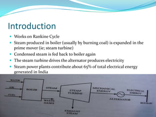
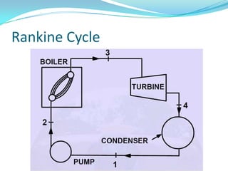
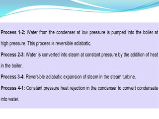

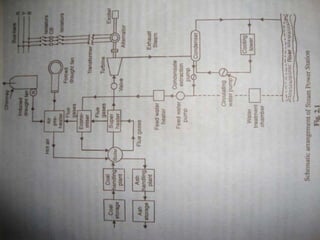
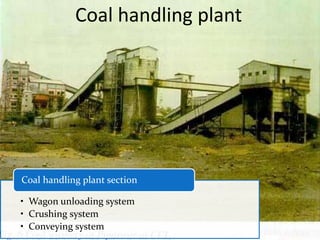
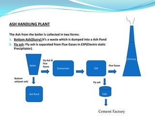
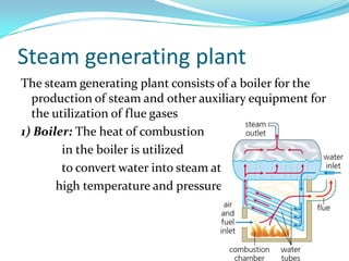
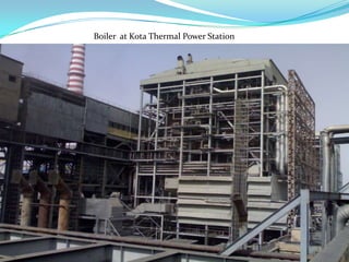


The document discusses the workings of a steam power plant based on the Rankine cycle, highlighting the production of steam through a boiler, its expansion in a steam turbine, and the conversion into electricity via an alternator. It details the coal and ash handling processes, the steam generation components such as the boiler and superheater, along with the cooling arrangements for steam condensation. Additionally, it emphasizes the importance of feed water and the overall efficiency of power generation in India.


![[PPT] on Steam Turbine](https://cdn.slidesharecdn.com/ss_thumbnails/spsharmafinalppt-140608082156-phpapp01-thumbnail.jpg?width=640&height=640&fit=bounds)


