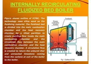
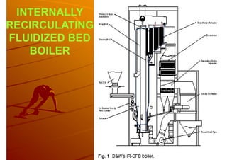
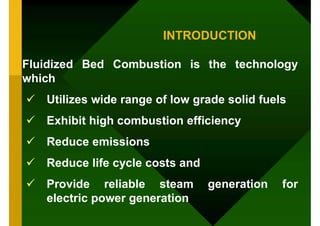
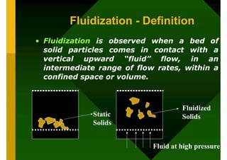
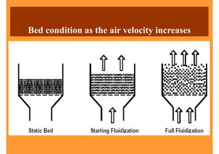
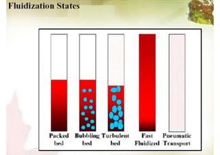
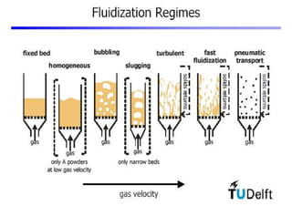
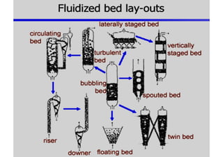
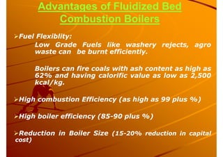
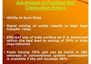
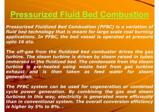
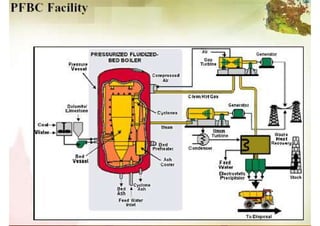
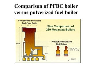
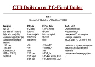
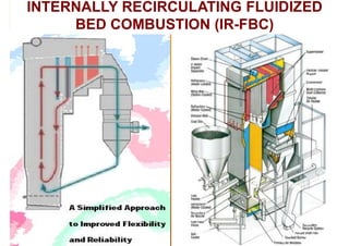
FBC BOILERS
Dr.M.Vivekanandan M.E.,PhD
Adjunct Faculty, Kongunadu College of Engineering
and Technology,
CEO, TryCAE Industrial Engineering Pvt Ltd.,
FBC BOILERS
Syllabus
• Introduction
• Mechanism of fluidized bed combustion,
Advantages,
• Types of FBC boilers, Operational features
• Retrofitting FBC system to conventional
boilers, saving potential.
INTRODUCTION
Fluidized Bed Combustion is the technology
which
 Utilizes wide range of low grade solid fuels
 Exhibit high combustion efficiency
 Reduce emissions
 Reduce life cycle costs and
 Provide reliable steam generation for
electric power generation
Fluidization - Definition
• Fluidization is observed when a bed of
solid particles comes in contact with a
vertical upward “fluid” flow, in an
intermediate range of flow rates, within a
confined space or volume.
Static
Solids
Fluid at high pressure
Fluidized
Solids
Evenly distributed air is passed upward through a
finely divided bed of sand supported on a fine mesh,
the particles are undisturbed at low velocity.As air
velocity is gradually increased, a stage is reached
when the individual particles are suspended in the air
stream.
Further, increase in velocity gives rise to bubble
formation, vigorous turbulence and rapid mixing.
The bed of solid particles exhibits the properties of a
boiling liquid. This state is called be fluidized.
Burning of fuel in such state is known as Fluidized Bed
Combustion
Combustion takes place at about 840OC to 950OC.
Principle of fluidization
Bed condition as the air velocity increases
Fluidized Bed
Advantages of Fluidized Bed
Combustion Boilers
Fuel Flexiblity:
Low Grade Fuels like washery rejects, agro
waste can be burnt efficiently.
Boilers can fire coals with ash content as high as
62% and having calorific value as low as 2,500
kcal/kg.
High combustion Efficiency (as high as 99 plus %)
High boiler efficiency (85-90 plus %)
Reduction in Boiler Size (15-20% reduction in capital
cost)
Advantages of Fluidized Bed
Combustion Boilers
Ability to burn fines
Rapid mixing of solids results in high heat
transfer rates.
Efficient use of tube surface as it is immersed
within the bed lead to saving of 75% in tube
requirements
Fuels having 75% ash can be burnt in FBC
whereas in conventional system combustion
is unstable if the ash exceeds 48%
Advantages of Fluidized Bed
Combustion Boilers
 Pollution Control:
sulfur removal without need for scrubbers
Low NOx emission due to staged combustion
and changing of the primary to secondary air
ratio
Only fuel bound nitrogen (fuel NOx)
converted to NOx (thermally formed NOx is
negligible)
Advantages of Fluidized Bed
Combustion Boilers
 High turndown and load following ability
 Load changes greater than 5% per minute
 Low Corrosion and Erosion
less due to lower combustion temperature, softness of ash
and low particle velocity (of the order of 1 m/sec).
 No Clinker Formation as
temperature of the furnace is in the range of 750–900o C.
Advantages of Fluidized Bed
Combustion Boilers
Less Excess Air – Higher CO2 in Flue Gas:
20 – 25% excess air only.
No Slagging in the Furnace-No Soot
Blowing:
volatilization of alkali components in
ash does not take place and the ash is
non sticky (dry ash).
Low maintenance
Advantages of Fluidized Bed
Combustion Boilers
100 % Depreciation
No manual feeding-less man power
No manual ash removal-ash removal
easier-lesser manpower-lesser time
consumption
Simple operation, Quick startup, Fast
response
STARTING OF FBC SYSTEM
Before coal can be fired in a fluid bed, the bed
material must be preheated to the ignition
temperature of the coal with auxiliary burners.
Two methods are commonly used for this:
1. Preheating of the bed material using oil
or gas burners
2. Preheating the fluidizing air with oil or
gas burners and introducing through the
nozzle bottom into the bed at 500 deg C.
TYPES OF FLUIDIZED BED
COMBUSTION
1. Atmospheric or Bubbling Fluidized Bed
Combustion (AFBC)
2. Circulating Fluidized Bed Combustion (CFBC)
3. Pressurized Fluidized Bed Combustion
(PFBC)
4. Internally Re Circulating – Circulating
Fluidized Bed Combustion (IR-CFBC)
AFBC or Bubbling Bed
Features of bubbling bed
boiler
AFBC use the in-bed
evaporator tubes for
extracting the heat from the
bed to maintain the bed
temperature.
The bubbling bed has heat
transfer tubes in the bed of
limestone, sand and fuel.
The velocity of fluidizing air
is in the range of 1.2 to 3.7
m /sec. Very little material
leaves the bubbling bed –
about 2 to 4 kgs of solids
are recycled per kg of fuel
burned.
Features of Bubbling Bed Boiler
The bed depth is usually 0.9 m to 1.5 meter
deep and the pressure drop averages about 1
inch of water per inch of bed depth.
Coal is crushed to a size of 1 – 10 mm and fed
to the combustion chamber.
The atmospheric air, which acts as both the
fluidization air and combustion air, is delivered
at a pressure, and flows through the bed after
being preheated by the exhaust flue gases. The
in-bed tubes carrying water generally act as
the evaporator.
Features of Bubbling Bed Boiler
If temperature exceeds 950oC , there is
risk of clinker formation in the bed and
combustion efficiency declines below
800oC.
For efficient sulfur retention the
temperature should be in the range of
800oC to 850oC.
FUEL FEEDING
Underfeed System
- it provides positive load and
- a compact design but,
- costly in operation
Overfeed System
- it is simple in operation and
- economical in running but,
- results in smaller output per sq.m area,
- provides poor desulphurization performance
Description Over bed Under bed
Distribution of
fuel and air
Poor Good
Unburnt
carryover of
fines
High-needs
double sieving
Low
Combustion
efficiency
Bare
More by about
7%
Recycle
requirement
High Very less
Power
requirement
Bare
Marginally
higher
Part load
operation
Warranty
segmentation
Segmentation
only in airbox
Startup Complicated simple
Circulating Fluidized Bed
With higher air velocities, the bed particles leave the
combustion with the flue gases so that solids
recirculation is necessary to maintain circulating
fluidized bed.
The mean solids velocity increases at a slower rate
than does the gas velocity, as illustrated in Figure
Therefore, a maximum slip velocity between the
solids and the gas can be achieved resulting in good
heat transfer and contact time with the limestone, for
sulfur dioxide removal.
Circulating Fluidized Bed
Solids
High Pressure Fluid
To Recirculation of
the Solids
Spent Fluid
Solids
RISER
STAND PIPE
CYCLONE
Relation between gas velocity and solid velocity
Circulating Fluidized Bed
Combustion (CFBC)
(6 –12 mm size) fuel and limestone are injected
into the furnace
Fluidizing velocity 3.7-9 m/s
The particles are suspended in a stream of
upwardly flowing air (60-70% of the total air),
which enters the bottom of the furnace through
air distribution nozzles. The balance of
combustion air is admitted above the bottom of
the furnace as secondary air.
Circulating Fluidized Bed
Combustion (CFBC)
While combustion takes place at 840-900oC,
the fine particles (<450 microns) are
elutriated out of the furnace with flue gas
velocity of 4-6 m/s. The particles are then
collected by the solids separators and
circulated back into the furnace. This
combustion process is called circulating
fluidized bed (CFB).
Circulating Fluidized Bed
Combustion (CFBC)
There are no steam generations tube immersed in
the bed. Generation and super heating of steam
takes place in the convection section, water
walls, at the exit of the riser.
CFBC boilers are generally more economical than
AFBC boilers for industrial application requiring
more than 75 – 100 T/hr of steam.
Performance of CFBC
The temperature of about 870oC is reasonably constant
throughout the process because of the high turbulence and
circulation of solids. The low combustion temperature also
results in minimal NOx formation.
Sulfur present in the fuel is retained in the circulating solids in
the form of calcium sulfate is removed in solid form. The use
of limestone or dolomite sorbents allows a higher sulfur
retention rate, and limestone requirements have been
demonstrated to be substantially less than with bubbling bed
combustor.
– Oxidation of sulfur
S+O2 --> SO2
– Limestone is calcined to form calcium oxide
CaCO3 --> CaO + CO2 –425 kcal/kg (of CaCO3)
– Sulfur dioxide gas reacts with solid CaO
SO2 + 1/2 O2 + CaO --> CaSO4 (Solid) +3740 kcal/kg (of S)
Variation of sulfur retention with CaO/S Ratio
10
100
CaO/S Molar Ratio
Sulfur Retention %
Variation of sulfur retention
with bed temperature
50
100
Sulfur Retention %
800 850 900 950
Bed Temperature deg C
Performance of CFBC
The combustion air is supplied at 1.5 to 2 psig
rather than 3-5 psig as required by bubbling bed
combustors.
It has high combustion efficiency.
It has a better turndown ratio than bubbling bed
systems.
Comparison of CFB with
Spreader Stoker and
Pulverized Fuel fired boiler
Characteristi
cs
FBC Spreader
stoker
PF fired
boiler
Fuel quality,
ash, CV, VM,
size distribution
Has no effect on
operation
Output
affected by
coal quality
Output
affected by
coal quality
Maintenance No moving parts
less maintenance
Moving grate
in high temp.
zone, requires
frequent
maintenance
Frequent
maintenace
due to
pulverizer
Efficiency for
typical Indian
coal 40% ash
About 86% Around 76% 86%-87%
Efficiency at
low load
Better Poor Less
Soot blowers Not required Necessary Necessary
NOx formation Low High high
Pressurized
Fluidized
Bed
Combustion
(PFBC)
Pressurized Fluid Bed Combustion
Pressurized Fluidized Bed Combustion (PFBC) is a variation of
fluid bed technology that is meant for large scale coal burning
applications. In PFBC, the bed vessel is operated at pressure
upto 16 ata.
The off-gas from the fluidized bed combustor drives the gas
turbine. The steam turbine is driven by steam raised in tubes
immersed in the fluidized bed. The condensate from the steam
turbine is pre-heated using waste heat from gas turbine
exhaust and is then taken as feed water for steam
generation.
The PFBC system can be used for cogeneration or combined
cycle power generation. By combining the gas and steam
turbines in this way, electricity is generated more efficiently
than in conventional system. The overall conversion efficiency
is higher by 5% to 8%. .
Comparison of PFBC boiler
versus pulverized fuel boiler
CFB Boiler over PC-Fired Boiler
INTERNALLY RECIRCULATING FLUIDIZED
BED COMBUSTION (IR-FBC)
INTERNALLY RECIRCULATING
FLUIDIZED BED BOILER
Figure shows outline of ICFBC. The
technology uses silica sand as the
fluidizing material. The fluidized bed
is divided into the main combustion
chamber and the heat recovery
chamber by a tilted partition to
create swirling flow inside the main
combustion chamber and the
circulation flow between the main
combustion chamber and the heat
recovery chamber. A circulation flow
is created to return the unburnt char
and unreacted limestone coming
from the cyclone at exit of the boiler
to the boiler.
 The swirling flow in the main combustion chamber
is created by dividing the window box in the main
combustion chamber to three sections, and by forming
a weak fluidized bed (moving bed) at the center
section introducing small amount of air, while forming
rigorous fluidized bed at both end-sections
introducing large amount of air.
 As a result, the center section of the main
combustion chamber forms a slow downward moving
bed, and the fluidizing material which is vigorously
blown up from both ends sediments at the center
section, and then ascends at both end-sections, thus
creating the swirling flow.
 The circulation flow between the main combustion
chamber and the heat recovery chamber is created by the
movement described below. A portion of the fluidizing material
which is vigorously blown up at both end-sections in the main
combustion chamber turns the flow direction toward the heat
recovery chamber at above the tilted partition. The heat
recovery chamber forms mild fluidized bed (downward moving
bed) by the circulation bed air injected from under the
chamber.
 Accordingly, the fluidizing material circulates from the
main combustion chamber to the heat recovery chamber, and
again to the main combustion chamber from the lower part of
the heat recovery chamber. Since the heat recovery chamber is
equipped with heat transfer tubes, the circulation flow
recovers the thermal energy in the main combustion chamber.
INTERNALLY
RECIRCULATING
FLUIDIZED BED
BOILER
 The circulation flow coming from the cyclone
at exit of the boiler passes through the cyclone
or other means to collect unburnt char, emitted
fluidizing material, and unreacted limestone,
and then returns to the main combustion
chamber or the heat recovery chamber using
screw conveyer, pneumatic conveyer, or other
means.
 The circulation flow is extremely effective to
increase combustion efficiency, to decrease NOx
generation, and to increase desulfurization
efficiency.
Retrofitting of FBC Systems to
Conventional Boilers
Successfully carried out both in India and abroad.
The important aspects to be considered in retrofit projects
are:Water/steam circulation design, Furnace bottom-grate
clearance, Type of particulate control device, Fan capacity,
Availability of space.
Retrofitting of a fluidized bed combustor to a conventional stoker
fired water tube boiler may involve:
The replacement of grate by a distributor plate with short stand
pipes for admitting air from the wind box located underneath.
Installation of stand pipes to remove ash from the bed.
Provision of horizontal hair pin tubes in the bed with a pump for
forced circulation from the boiler drum.
Modification of crusher to size the coal/limestone mixture for
pneumatic underbed injection of the mixture.
Disadvantages of FBC Boilers
Startup procedure more complex
Control response almost instantaneous
Bed turndown capability not clear
Corrosion susceptibility in bubbling bed
Complex under-bed fuel-feed system
required for some bubbling beds
CORROSION IN FBC SYSTEM
The operation of bed at elevated temperature
leads to erosion and corrosion of the immersed
tubes.
More-over, there is higher tendency of erosion due
to impact of particles.
The erosion of tubes by impacting of fly ash
becomes serious at velocities greater than 25m/s
Overall conditions are likely to cause severe
sulfidation and oxidation of tubes
Low erosion rates are characterized by dilute
combustion (i.e bed containing only 2% fuel)
How to reduce corrosion problem?
The modification in design and mode
in operation can reduce the problem
of corrosion
Absorption or neutralization of
corrosive chemical species by proper
selection of blending materials like
sodium vanadium and chlorine with
fuel

Fbc boilers

  • 1.
    FBC BOILERS Dr.M.Vivekanandan M.E.,PhD AdjunctFaculty, Kongunadu College of Engineering and Technology, CEO, TryCAE Industrial Engineering Pvt Ltd.,
  • 2.
    FBC BOILERS Syllabus • Introduction •Mechanism of fluidized bed combustion, Advantages, • Types of FBC boilers, Operational features • Retrofitting FBC system to conventional boilers, saving potential.
  • 3.
    INTRODUCTION Fluidized Bed Combustionis the technology which  Utilizes wide range of low grade solid fuels  Exhibit high combustion efficiency  Reduce emissions  Reduce life cycle costs and  Provide reliable steam generation for electric power generation
  • 4.
    Fluidization - Definition •Fluidization is observed when a bed of solid particles comes in contact with a vertical upward “fluid” flow, in an intermediate range of flow rates, within a confined space or volume. Static Solids Fluid at high pressure Fluidized Solids
  • 5.
    Evenly distributed airis passed upward through a finely divided bed of sand supported on a fine mesh, the particles are undisturbed at low velocity.As air velocity is gradually increased, a stage is reached when the individual particles are suspended in the air stream. Further, increase in velocity gives rise to bubble formation, vigorous turbulence and rapid mixing. The bed of solid particles exhibits the properties of a boiling liquid. This state is called be fluidized. Burning of fuel in such state is known as Fluidized Bed Combustion Combustion takes place at about 840OC to 950OC. Principle of fluidization
  • 8.
    Bed condition asthe air velocity increases
  • 12.
  • 14.
    Advantages of FluidizedBed Combustion Boilers Fuel Flexiblity: Low Grade Fuels like washery rejects, agro waste can be burnt efficiently. Boilers can fire coals with ash content as high as 62% and having calorific value as low as 2,500 kcal/kg. High combustion Efficiency (as high as 99 plus %) High boiler efficiency (85-90 plus %) Reduction in Boiler Size (15-20% reduction in capital cost)
  • 15.
    Advantages of FluidizedBed Combustion Boilers Ability to burn fines Rapid mixing of solids results in high heat transfer rates. Efficient use of tube surface as it is immersed within the bed lead to saving of 75% in tube requirements Fuels having 75% ash can be burnt in FBC whereas in conventional system combustion is unstable if the ash exceeds 48%
  • 16.
    Advantages of FluidizedBed Combustion Boilers  Pollution Control: sulfur removal without need for scrubbers Low NOx emission due to staged combustion and changing of the primary to secondary air ratio Only fuel bound nitrogen (fuel NOx) converted to NOx (thermally formed NOx is negligible)
  • 17.
    Advantages of FluidizedBed Combustion Boilers  High turndown and load following ability  Load changes greater than 5% per minute  Low Corrosion and Erosion less due to lower combustion temperature, softness of ash and low particle velocity (of the order of 1 m/sec).  No Clinker Formation as temperature of the furnace is in the range of 750–900o C.
  • 18.
    Advantages of FluidizedBed Combustion Boilers Less Excess Air – Higher CO2 in Flue Gas: 20 – 25% excess air only. No Slagging in the Furnace-No Soot Blowing: volatilization of alkali components in ash does not take place and the ash is non sticky (dry ash). Low maintenance
  • 19.
    Advantages of FluidizedBed Combustion Boilers 100 % Depreciation No manual feeding-less man power No manual ash removal-ash removal easier-lesser manpower-lesser time consumption Simple operation, Quick startup, Fast response
  • 20.
    STARTING OF FBCSYSTEM Before coal can be fired in a fluid bed, the bed material must be preheated to the ignition temperature of the coal with auxiliary burners. Two methods are commonly used for this: 1. Preheating of the bed material using oil or gas burners 2. Preheating the fluidizing air with oil or gas burners and introducing through the nozzle bottom into the bed at 500 deg C.
  • 21.
    TYPES OF FLUIDIZEDBED COMBUSTION 1. Atmospheric or Bubbling Fluidized Bed Combustion (AFBC) 2. Circulating Fluidized Bed Combustion (CFBC) 3. Pressurized Fluidized Bed Combustion (PFBC) 4. Internally Re Circulating – Circulating Fluidized Bed Combustion (IR-CFBC)
  • 22.
    AFBC or BubblingBed Features of bubbling bed boiler AFBC use the in-bed evaporator tubes for extracting the heat from the bed to maintain the bed temperature. The bubbling bed has heat transfer tubes in the bed of limestone, sand and fuel. The velocity of fluidizing air is in the range of 1.2 to 3.7 m /sec. Very little material leaves the bubbling bed – about 2 to 4 kgs of solids are recycled per kg of fuel burned.
  • 23.
    Features of BubblingBed Boiler The bed depth is usually 0.9 m to 1.5 meter deep and the pressure drop averages about 1 inch of water per inch of bed depth. Coal is crushed to a size of 1 – 10 mm and fed to the combustion chamber. The atmospheric air, which acts as both the fluidization air and combustion air, is delivered at a pressure, and flows through the bed after being preheated by the exhaust flue gases. The in-bed tubes carrying water generally act as the evaporator.
  • 24.
    Features of BubblingBed Boiler If temperature exceeds 950oC , there is risk of clinker formation in the bed and combustion efficiency declines below 800oC. For efficient sulfur retention the temperature should be in the range of 800oC to 850oC.
  • 25.
    FUEL FEEDING Underfeed System -it provides positive load and - a compact design but, - costly in operation Overfeed System - it is simple in operation and - economical in running but, - results in smaller output per sq.m area, - provides poor desulphurization performance
  • 26.
    Description Over bedUnder bed Distribution of fuel and air Poor Good Unburnt carryover of fines High-needs double sieving Low Combustion efficiency Bare More by about 7% Recycle requirement High Very less Power requirement Bare Marginally higher Part load operation Warranty segmentation Segmentation only in airbox Startup Complicated simple
  • 27.
    Circulating Fluidized Bed Withhigher air velocities, the bed particles leave the combustion with the flue gases so that solids recirculation is necessary to maintain circulating fluidized bed. The mean solids velocity increases at a slower rate than does the gas velocity, as illustrated in Figure Therefore, a maximum slip velocity between the solids and the gas can be achieved resulting in good heat transfer and contact time with the limestone, for sulfur dioxide removal.
  • 28.
    Circulating Fluidized Bed Solids HighPressure Fluid To Recirculation of the Solids Spent Fluid Solids RISER STAND PIPE CYCLONE
  • 29.
    Relation between gasvelocity and solid velocity
  • 30.
    Circulating Fluidized Bed Combustion(CFBC) (6 –12 mm size) fuel and limestone are injected into the furnace Fluidizing velocity 3.7-9 m/s The particles are suspended in a stream of upwardly flowing air (60-70% of the total air), which enters the bottom of the furnace through air distribution nozzles. The balance of combustion air is admitted above the bottom of the furnace as secondary air.
  • 31.
    Circulating Fluidized Bed Combustion(CFBC) While combustion takes place at 840-900oC, the fine particles (<450 microns) are elutriated out of the furnace with flue gas velocity of 4-6 m/s. The particles are then collected by the solids separators and circulated back into the furnace. This combustion process is called circulating fluidized bed (CFB).
  • 32.
    Circulating Fluidized Bed Combustion(CFBC) There are no steam generations tube immersed in the bed. Generation and super heating of steam takes place in the convection section, water walls, at the exit of the riser. CFBC boilers are generally more economical than AFBC boilers for industrial application requiring more than 75 – 100 T/hr of steam.
  • 35.
    Performance of CFBC Thetemperature of about 870oC is reasonably constant throughout the process because of the high turbulence and circulation of solids. The low combustion temperature also results in minimal NOx formation. Sulfur present in the fuel is retained in the circulating solids in the form of calcium sulfate is removed in solid form. The use of limestone or dolomite sorbents allows a higher sulfur retention rate, and limestone requirements have been demonstrated to be substantially less than with bubbling bed combustor. – Oxidation of sulfur S+O2 --> SO2 – Limestone is calcined to form calcium oxide CaCO3 --> CaO + CO2 –425 kcal/kg (of CaCO3) – Sulfur dioxide gas reacts with solid CaO SO2 + 1/2 O2 + CaO --> CaSO4 (Solid) +3740 kcal/kg (of S)
  • 36.
    Variation of sulfurretention with CaO/S Ratio 10 100 CaO/S Molar Ratio Sulfur Retention %
  • 37.
    Variation of sulfurretention with bed temperature 50 100 Sulfur Retention % 800 850 900 950 Bed Temperature deg C
  • 38.
    Performance of CFBC Thecombustion air is supplied at 1.5 to 2 psig rather than 3-5 psig as required by bubbling bed combustors. It has high combustion efficiency. It has a better turndown ratio than bubbling bed systems.
  • 39.
    Comparison of CFBwith Spreader Stoker and Pulverized Fuel fired boiler
  • 40.
    Characteristi cs FBC Spreader stoker PF fired boiler Fuelquality, ash, CV, VM, size distribution Has no effect on operation Output affected by coal quality Output affected by coal quality Maintenance No moving parts less maintenance Moving grate in high temp. zone, requires frequent maintenance Frequent maintenace due to pulverizer Efficiency for typical Indian coal 40% ash About 86% Around 76% 86%-87% Efficiency at low load Better Poor Less Soot blowers Not required Necessary Necessary NOx formation Low High high
  • 41.
  • 42.
    Pressurized Fluid BedCombustion Pressurized Fluidized Bed Combustion (PFBC) is a variation of fluid bed technology that is meant for large scale coal burning applications. In PFBC, the bed vessel is operated at pressure upto 16 ata. The off-gas from the fluidized bed combustor drives the gas turbine. The steam turbine is driven by steam raised in tubes immersed in the fluidized bed. The condensate from the steam turbine is pre-heated using waste heat from gas turbine exhaust and is then taken as feed water for steam generation. The PFBC system can be used for cogeneration or combined cycle power generation. By combining the gas and steam turbines in this way, electricity is generated more efficiently than in conventional system. The overall conversion efficiency is higher by 5% to 8%. .
  • 45.
    Comparison of PFBCboiler versus pulverized fuel boiler
  • 46.
    CFB Boiler overPC-Fired Boiler
  • 47.
  • 48.
    INTERNALLY RECIRCULATING FLUIDIZED BEDBOILER Figure shows outline of ICFBC. The technology uses silica sand as the fluidizing material. The fluidized bed is divided into the main combustion chamber and the heat recovery chamber by a tilted partition to create swirling flow inside the main combustion chamber and the circulation flow between the main combustion chamber and the heat recovery chamber. A circulation flow is created to return the unburnt char and unreacted limestone coming from the cyclone at exit of the boiler to the boiler.
  • 49.
     The swirlingflow in the main combustion chamber is created by dividing the window box in the main combustion chamber to three sections, and by forming a weak fluidized bed (moving bed) at the center section introducing small amount of air, while forming rigorous fluidized bed at both end-sections introducing large amount of air.  As a result, the center section of the main combustion chamber forms a slow downward moving bed, and the fluidizing material which is vigorously blown up from both ends sediments at the center section, and then ascends at both end-sections, thus creating the swirling flow.
  • 50.
     The circulationflow between the main combustion chamber and the heat recovery chamber is created by the movement described below. A portion of the fluidizing material which is vigorously blown up at both end-sections in the main combustion chamber turns the flow direction toward the heat recovery chamber at above the tilted partition. The heat recovery chamber forms mild fluidized bed (downward moving bed) by the circulation bed air injected from under the chamber.  Accordingly, the fluidizing material circulates from the main combustion chamber to the heat recovery chamber, and again to the main combustion chamber from the lower part of the heat recovery chamber. Since the heat recovery chamber is equipped with heat transfer tubes, the circulation flow recovers the thermal energy in the main combustion chamber.
  • 51.
  • 52.
     The circulationflow coming from the cyclone at exit of the boiler passes through the cyclone or other means to collect unburnt char, emitted fluidizing material, and unreacted limestone, and then returns to the main combustion chamber or the heat recovery chamber using screw conveyer, pneumatic conveyer, or other means.  The circulation flow is extremely effective to increase combustion efficiency, to decrease NOx generation, and to increase desulfurization efficiency.
  • 53.
    Retrofitting of FBCSystems to Conventional Boilers Successfully carried out both in India and abroad. The important aspects to be considered in retrofit projects are:Water/steam circulation design, Furnace bottom-grate clearance, Type of particulate control device, Fan capacity, Availability of space. Retrofitting of a fluidized bed combustor to a conventional stoker fired water tube boiler may involve: The replacement of grate by a distributor plate with short stand pipes for admitting air from the wind box located underneath. Installation of stand pipes to remove ash from the bed. Provision of horizontal hair pin tubes in the bed with a pump for forced circulation from the boiler drum. Modification of crusher to size the coal/limestone mixture for pneumatic underbed injection of the mixture.
  • 54.
    Disadvantages of FBCBoilers Startup procedure more complex Control response almost instantaneous Bed turndown capability not clear Corrosion susceptibility in bubbling bed Complex under-bed fuel-feed system required for some bubbling beds
  • 55.
    CORROSION IN FBCSYSTEM The operation of bed at elevated temperature leads to erosion and corrosion of the immersed tubes. More-over, there is higher tendency of erosion due to impact of particles. The erosion of tubes by impacting of fly ash becomes serious at velocities greater than 25m/s Overall conditions are likely to cause severe sulfidation and oxidation of tubes Low erosion rates are characterized by dilute combustion (i.e bed containing only 2% fuel)
  • 56.
    How to reducecorrosion problem? The modification in design and mode in operation can reduce the problem of corrosion Absorption or neutralization of corrosive chemical species by proper selection of blending materials like sodium vanadium and chlorine with fuel