Downloaded 568 times

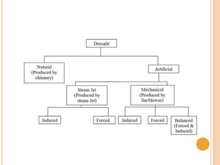
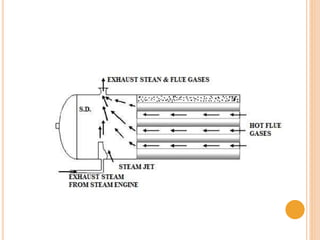

Boiler draught refers to the pressure difference between the air inside a boiler furnace and the outside air, which causes the flow of air and flue gases through the boiler. This pressure difference is necessary for proper combustion of fuel and removal of flue gases. Draught can be produced naturally through the use of a chimney, or artificially through mechanical fans or steam jets. Forced draught uses a fan before the furnace to push air and gases through, while induced draught uses a fan at the chimney to pull gases through. Balanced draught combines the two. Mechanical draught allows better control of the pressure but has higher costs than natural or steam jet draught.


![Gas turbine-power-plant[1]](https://cdn.slidesharecdn.com/ss_thumbnails/gas-turbine-power-plant1-150515182411-lva1-app6892-thumbnail.jpg?width=640&height=640&fit=bounds)