Downloaded 205 times

![ Figure (a) shows a member acted upon by three forces F1,
F2 and F3 and is in equilibrium as the lines of action of forces
intersect at one point O and the resultant is zero.
• This is verified by adding the forces vectorially [Fig.(b)].
• As the head of the last vector F3 meets the tail of the first
vector F1, the resultant is zero.
• Figure (d) shows a case where the magnitudes and
directions of the forces are the same as before, but the lines
of action of the forces do not intersect at one point.
• Thus, the member is not in equilibrium.](https://image.slidesharecdn.com/staticforceanalysis-160930122428/75/Static-Force-Analysis-12-2048.jpg)
![ Consider a member in equilibrium in which force F1 is completely
known, F2 known in direction only and F3 completely unknown.
• The point of applications of F1 , F2 and F3 are A, B and C
respectively.
• To solve such a problem, first find the point of concurrency O from
the two forces with known directions, i.e. from F1, and F2.
• Joining O with C gives the line of action of the third force F3.
• To know the magnitudes of the forces F2 and F3, take a vector of
proper magnitude and direction to represent the force F1.
• From its two ends, draw lines parallel to lines of action of the forces
F2 and F3 forming a force triangle [Fig.].
• Mark arrowheads on F2 and F3 so that F1 , F2 and F3 are in the
same order.](https://image.slidesharecdn.com/staticforceanalysis-160930122428/75/Static-Force-Analysis-13-2048.jpg)


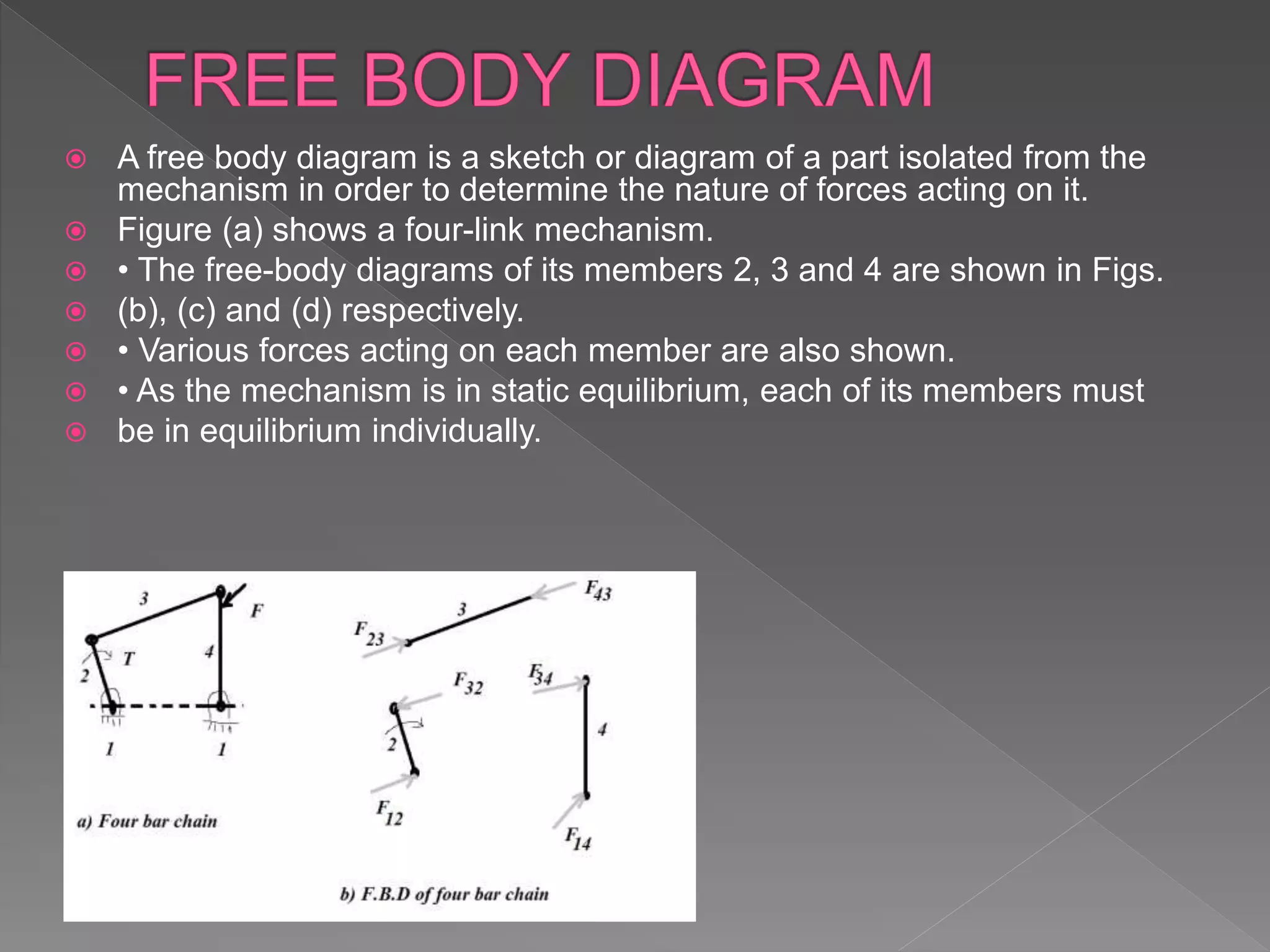
The document discusses Newton's laws of motion, detailing applied and constraint forces, and introduces concepts such as free body diagrams and static and dynamic equilibrium. It explains how forces influence the motion of bodies and provides conditions for equilibrium under various forces. Additionally, it covers the nature of friction and its role in opposing motion.


![Ctm 154[1]](https://cdn.slidesharecdn.com/ss_thumbnails/ctm1541-190506153756-thumbnail.jpg?width=640&height=640&fit=bounds)