Download as PDF, PPTX
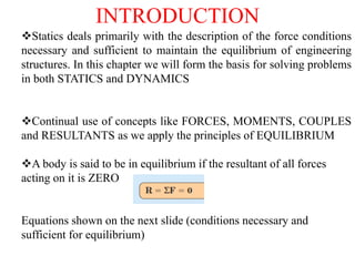
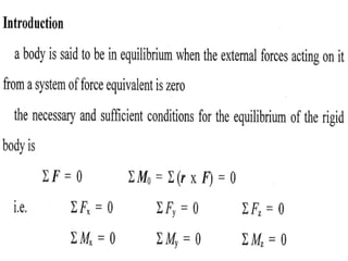
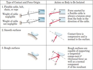
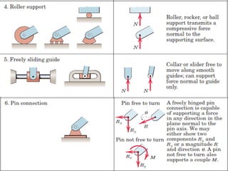
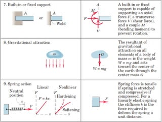
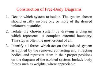
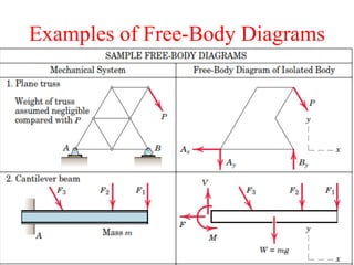
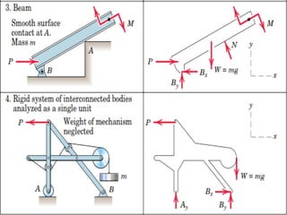
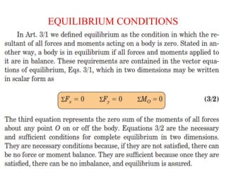
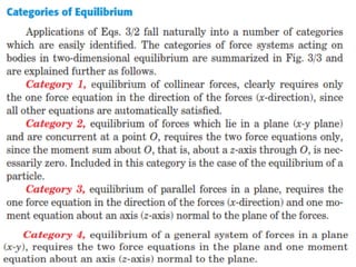
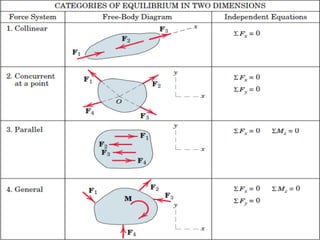
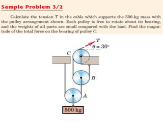
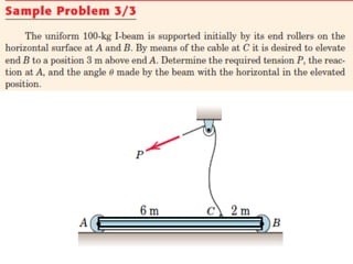
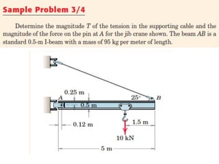
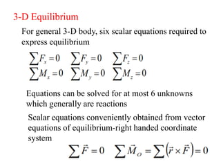
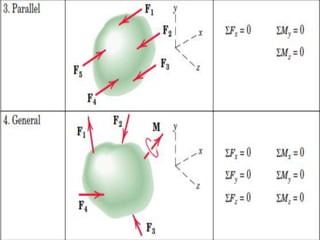
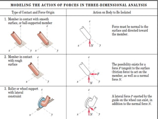
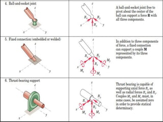
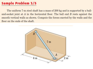
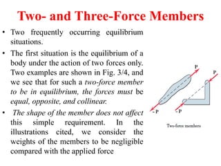
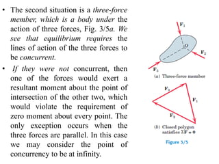
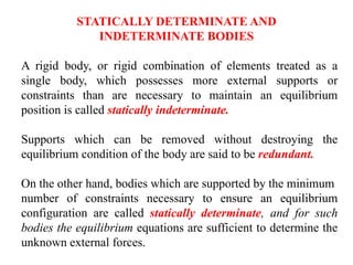

This document provides an introduction to the concept of equilibrium in statics. It discusses how to isolate a mechanical system and draw a free body diagram showing all external forces acting on it. For equilibrium in two dimensions, the forces must sum to zero in both the x and y directions. In three dimensions, six equations are required - the forces and moments must sum to zero in the x, y, and z directions as well as around each axis. Examples are given of two-force and three-force members in equilibrium. The document also defines statically determinate and indeterminate bodies.


![CONSTRUCTION [soil treatment, foundation backfill, Damp Proof Membrane[DPM] a...](https://cdn.slidesharecdn.com/ss_thumbnails/kahimba-181220112907-thumbnail.jpg?width=640&height=640&fit=bounds)