Downloaded 346 times


![DYNAMICS OF MACHINERY
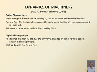
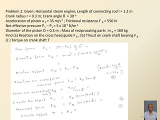
DYNAMIC FORCE ANALYSIS IN A RECIPROCATING ENGINE
Angular velocity of connecting rod, ω PC = ω cos θ / [ n 2 – sin 2 θ] ½
Angular acceleration of the connecting rod, α = – ω 2 sin θ [ n 2 – 1] / [ n 2 – sin 2 θ] 3/2
Crank Pin Effort (Force), FT = FQ sin (θ + φ) = [FP / cos φ] sin (θ + φ)
Crank Effort (Torque) , T = FT r = {[FP / cos φ] sin (θ + φ)} r
= FP r { sin θ +[sin 2 θ / [2 (n 2 – sin 2 θ)1/2]]}
Piston Effort [ Force on piston or cross head pin], FP =FL ± FI – RF ; where
FL is Net load on piston, FI is inertia force and RF is resistance offered.
Net load on piston, FL = P1 A1 – P2 A2
Inertia Force, FI = – m R a G = m R ω 2 r [cos θ + (cos 2θ)/n] where m R is mass of the
reciprocating body in kg and a G is linear acceleration of the centre of mass of the
body in m/s 2
10](https://image.slidesharecdn.com/unit1lectbyvrkdynofmachinery-140327160009-phpapp01/85/Unit1-lectbyvrk-dynofmachinery-10-320.jpg)
![DYNAMICS OF MACHINERY
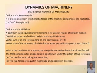
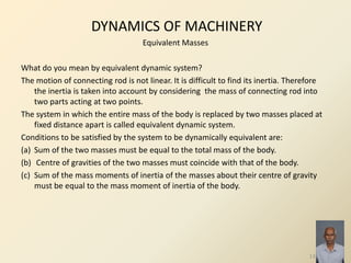
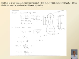
GAS FORCES – BEARING LOADS – CRANK SHAFT TORQUE
Gas Forces produce the net load on the piston.
Net load on piston, FL = P1 A1 – P2 A2
Inertia Force, FI = m R aG where m R is mass of the reciprocating body in kg and a G
is linear acceleration of the centre of mass of the body in m/s 2
Linear acceleration, a G = ω 2 r [cos θ + (cos 2θ)/n]
where n = l/r = Length of connecting rod / radius of crank
Bearing Loads
Thrust (Force) on crank shaft bearing, FB = FQ cos (θ + φ) = [FP / cos φ] cos (θ + φ)
Normal Force on cylinder wall, FN = FP tan (φ)
Piston Effort [ Force on piston or cross head pin], FP =FL ± FI – RF ; where
FL is Net load on piston, FI is inertia force and RF is resistance offered.
Crank Shaft Torque
Crank Effort (Torque) , T = FT r = [FP / cos φ] sin (θ + φ) r
= FP r { sin θ +[sin 2 θ / [2 (n 2 – sin 2 θ)1/2]]}
11](https://image.slidesharecdn.com/unit1lectbyvrkdynofmachinery-140327160009-phpapp01/85/Unit1-lectbyvrk-dynofmachinery-11-320.jpg)


![DYNAMICS OF MACHINERY
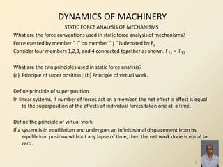
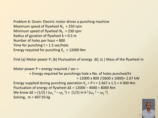
FLYWHEEL OF ENGINES
Define coefficient of fluctuation of speed.
It is the ratio of maximum fluctuation of speed to the mean speed.
CS = (N1 - N1) / [(N1+ N1)/2]
Define coefficient of fluctuation of energy.
It is the ratio of maximum fluctuation of energy to the work done per cycle.
CE = ΔE / W , ΔE = E max – E min
Define coefficient of steadiness.
Reciprocal of coefficient of fluctuation of speed is called coefficient of steadiness.
24](https://image.slidesharecdn.com/unit1lectbyvrkdynofmachinery-140327160009-phpapp01/85/Unit1-lectbyvrk-dynofmachinery-24-320.jpg)
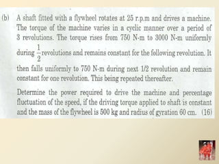
![DYNAMICS OF MACHINERY
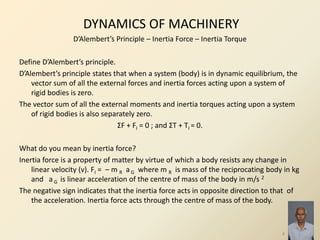
FLYWHEEL OF ENGINES
Why small flywheel is used in a multi cylinder engine?
In multi cylinder engine, total turning moment is the sum of the turning moments of
each cylinder at any instant. Therefore the fluctuations in the turning moment is
low and flywheel required is also small.
Mention the relation between peripheral velocity of flywheel rim and density of
material.
‘ v = * σ/ρ ] ½ where σ is hoop stress or tensile stress due to centrifugal
force in N/m 2 and ρ is density of rim material in kg/m3
Is work done by IC engine is positive?
In IC engine power is produced only during power stroke. Power is utilised during the
other strokes. Work done per cycle is less than work done during power stroke.
Hence net work done is always positive.
25](https://image.slidesharecdn.com/unit1lectbyvrkdynofmachinery-140327160009-phpapp01/85/Unit1-lectbyvrk-dynofmachinery-25-320.jpg)


![33
Unit-1: Formulae
Parameters involved are
x, r, l, l1, θ,φ, p1, p2, A1, A2, FR, mR, mC,
k or R
, n = l / r; sin φ = [sin θ] / n;
, x = r [ (1-cos θ) + (1/2n) sin2 θ]
, v p = ω r [ sin θ + (1/2n) sin 2θ]
, a p = ω2 r [ cos θ + (1/n) cos 2θ]
, ω pc = (ωcos θ) /n) ;
‘ α pc = – (ω 2 sin θ) /n) ;
FL = [p1 (п/4)D2 ] – [p2(п/4)(D – d )2 ]
FI = mR ω2 r [ cos θ + (1/n) cos 2θ]
Fp = FL – FI ± m g – FR
FQ = Fp / cos φ ; FN = Fp tan φ ;
FB = FQ cos (θ +φ) ;
FT = FQ sin (θ +φ) ;
T = FT r
Parameters involved are
‘ θ , α, σ, ρ, v, D, A, b, t, m, ω , k or
R, T, P, N, I, E, ΔE, Δ ω , ω, W, Cs, CE .
‘ v = √(σ/ρ) = п D N/60; ω = 2 п N/60
T mean = Wcycle / θ cycle ;
θ cycle = 4 п for 4 stroke IC engine;
θ cycle = 2 п for 2stroke IC engine;
Cs = (ω1 – ω 2)/ ω ; ω = (ω1 + ω 2)/ 2
Cs = (N1 – N 2)/ N ; N = (N1 + N 2)/ 2
Cs = (v1 – v2)/ v ; v = (v1 + v2)/ 2
P = Tmean ω
Wcycle = 60 P /(N/2) for 4 stroke cycle
Wcycle = 60 P / N for 2 stroke cycle
CE = ΔE/ Wcycle
‘ ΔE = m v2 Cs = 2 E Cs = m k2 ω2 Cs
= I ω2 Cs
I α = (T – T mean) = m k2 α](https://image.slidesharecdn.com/unit1lectbyvrkdynofmachinery-140327160009-phpapp01/85/Unit1-lectbyvrk-dynofmachinery-33-320.jpg)
![34
Unit-1: Formulae:
Parameters involved are
x, r, l, l1, θ,φ, p1, p2, A1, A2, FR, mR, mC,
k or R
FL = [p1 (п/4)D2 ] – [p2(п/4)(D – d )2 ]
FI = mR ω2 r [ cos θ + (1/n) cos 2θ]
Fp = FL – FI ± m g – FR
FQ = Fp / cos φ ; FN = Fp tan φ ;
FB = FQ cos (θ +φ) ;
FT = FQ sin (θ +φ) ;
T = FT r](https://image.slidesharecdn.com/unit1lectbyvrkdynofmachinery-140327160009-phpapp01/85/Unit1-lectbyvrk-dynofmachinery-34-320.jpg)


The document discusses static and dynamic force analysis of mechanisms. It defines key terms like static equilibrium, inertia force, inertia torque, and D'Alembert's principle. It explains the conditions for a body to be in equilibrium under different force configurations. Dynamic force analysis considers inertia forces to determine input torque required. Equivalent masses and Klein's construction diagram are discussed for dynamic analysis of reciprocating engines. Correction couple and torque are also summarized.