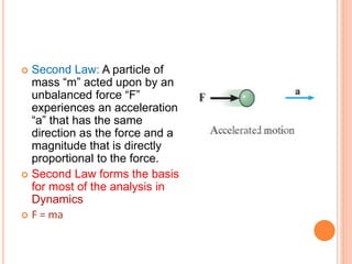
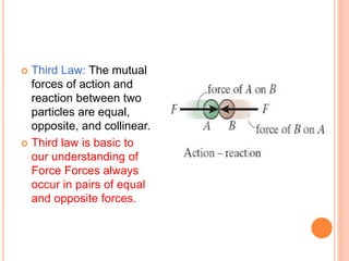
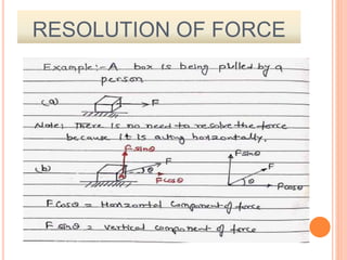
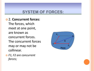
Engineering mechanics deals with the study of forces and their effects on bodies at rest or in motion. It is divided into statics, which studies forces on bodies at rest, and dynamics, which studies forces on bodies in motion. Applied mechanics is further divided into kinetics, which considers forces and motion, and kinematics, which considers motion alone. Mechanics uses concepts like forces, moments, equilibrium, and motion. Forces are described by their magnitude, direction, line of action, and point of application. Systems of forces include concurrent, coplanar, and collinear forces. The graphical and analytical methods can be used to determine the resultant of a system of forces, including the triangle law, polygon law, and resolution of forces.

![ Rigid body – The body which does not undergo
any change in shape and size after removal of
external applied force then the body is called as
rigid body. A rigid body (also known as a rigid
object) is a solid body in which deformation is zero
or so small it can be neglected.
No body is perfectly rigid in nature but it is assumed
to be rigid in the study of applied mechanics.
[Important to note]](https://image.slidesharecdn.com/force-1-231027170746-ae592d4c/85/FORCE-1-pptx-7-320.jpg)
![ ACTION AND REACTION FORCE: Forces always act in pairs
and always act in opposite directions. When you push on an
object, the object pushes back with an equal force. Think of a
pile of books on a table. The weight of the books exerts a
downward force on the table. This is the action force [ACTIVE
FORCE]. The table exerts an equal upward force on the books.
This is the reaction force [REACTIVE FORCE].](https://image.slidesharecdn.com/force-1-231027170746-ae592d4c/85/FORCE-1-pptx-16-320.jpg)
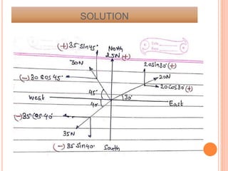
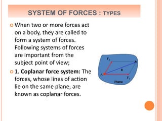
![SYSTEM OF FORCES
When two or more forces act on a body, they are called
to form a system of forces.
We will consider two situations ,
I)when only two forces are acting.
II)when more than two forces are acting.
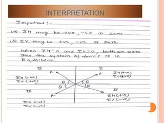
The system of forces may or may not be in equilibrium .
A] If the system is not in equilibrium then there is need
to find the resultant of the system.
B] If the system is in equilibrium ,then we will apply
conditions of equilibrium to find out the unknown
parameter.](https://image.slidesharecdn.com/force-1-231027170746-ae592d4c/85/FORCE-1-pptx-17-320.jpg)
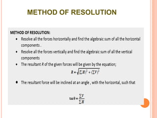
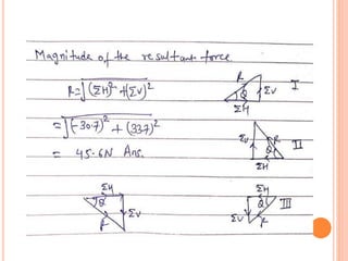
![ METHODS FOR THE RESULTANT FORCE: Though there are
many methods for finding out the resultant force of a
number of given forces, yet the following are important from
the subject point of view :
1. Analytical method [using formula]
2. Graphical method[using vector diagram]
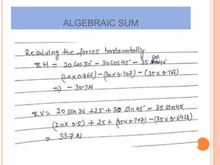
ANALYTICAL METHOD FOR RESULTANT FORCE: The resultant
force, of a given system of forces, may be found out
analytically by the following methods :
1. Parallelogram law of forces[for 2force only]
2. Method of resolution [for more than 2force]](https://image.slidesharecdn.com/force-1-231027170746-ae592d4c/85/FORCE-1-pptx-19-320.jpg)
![SPACE DIAGRAM [POSITION DIAGRAM]](https://image.slidesharecdn.com/force-1-231027170746-ae592d4c/85/FORCE-1-pptx-29-320.jpg)
![ GRAPHICAL METHOD FOR RESULTANT FORCE: The
resultant force, of a given system of forces, may be
found out graphically by the following methods :
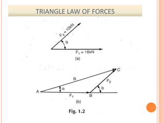
1. Triangle law of forces[for 2force only]
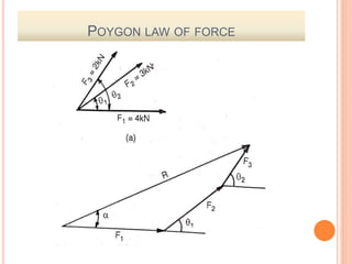
2. polygon law of forces[for [for more than 2force]](https://image.slidesharecdn.com/force-1-231027170746-ae592d4c/85/FORCE-1-pptx-35-320.jpg)
![SYLLABUS
Engineering Mechanics [BT-204]
Unit IV: Forces and Equilibrium: Graphical and
Analytical Treatment of Concurrent and
nonconcurrent Co- planner forces, free Diagram,
Force Diagram and Bow’s notations,
Application of Equilibrium Concepts: Analysis of
plane Trusses: Method of joints, Method of
Sections. Frictional force in equilibrium problems](https://image.slidesharecdn.com/force-1-231027170746-ae592d4c/85/FORCE-1-pptx-36-320.jpg)
![REFERENCE BOOKS:
2.]Prasad I.B., Applied Mechanics, Khanna
Publication.
10.] R.C. Hibbler – Engineering Mechanics: Statics
& Dynamics.
11.] A. Boresi & Schmidt- Engineering Mechines-
statics dynamics, Thomson’ Books
12.] R.K. Rajput, Engineering Mechanics S.Chand
& Co.
R.S.Khurmi](https://image.slidesharecdn.com/force-1-231027170746-ae592d4c/85/FORCE-1-pptx-38-320.jpg)
![JUNE 2020[ GRADING SYSTEM]
2. a) State and prove Lami’s theorem?
b) State and prove Varignon’s theorem?
7. Define coplanar and concurrent forces. Also
define free body diagram.](https://image.slidesharecdn.com/force-1-231027170746-ae592d4c/85/FORCE-1-pptx-52-320.jpg)


![Ctm 154[1]](https://cdn.slidesharecdn.com/ss_thumbnails/ctm1541-190506153756-thumbnail.jpg?width=640&height=640&fit=bounds)


