Downloaded 309 times
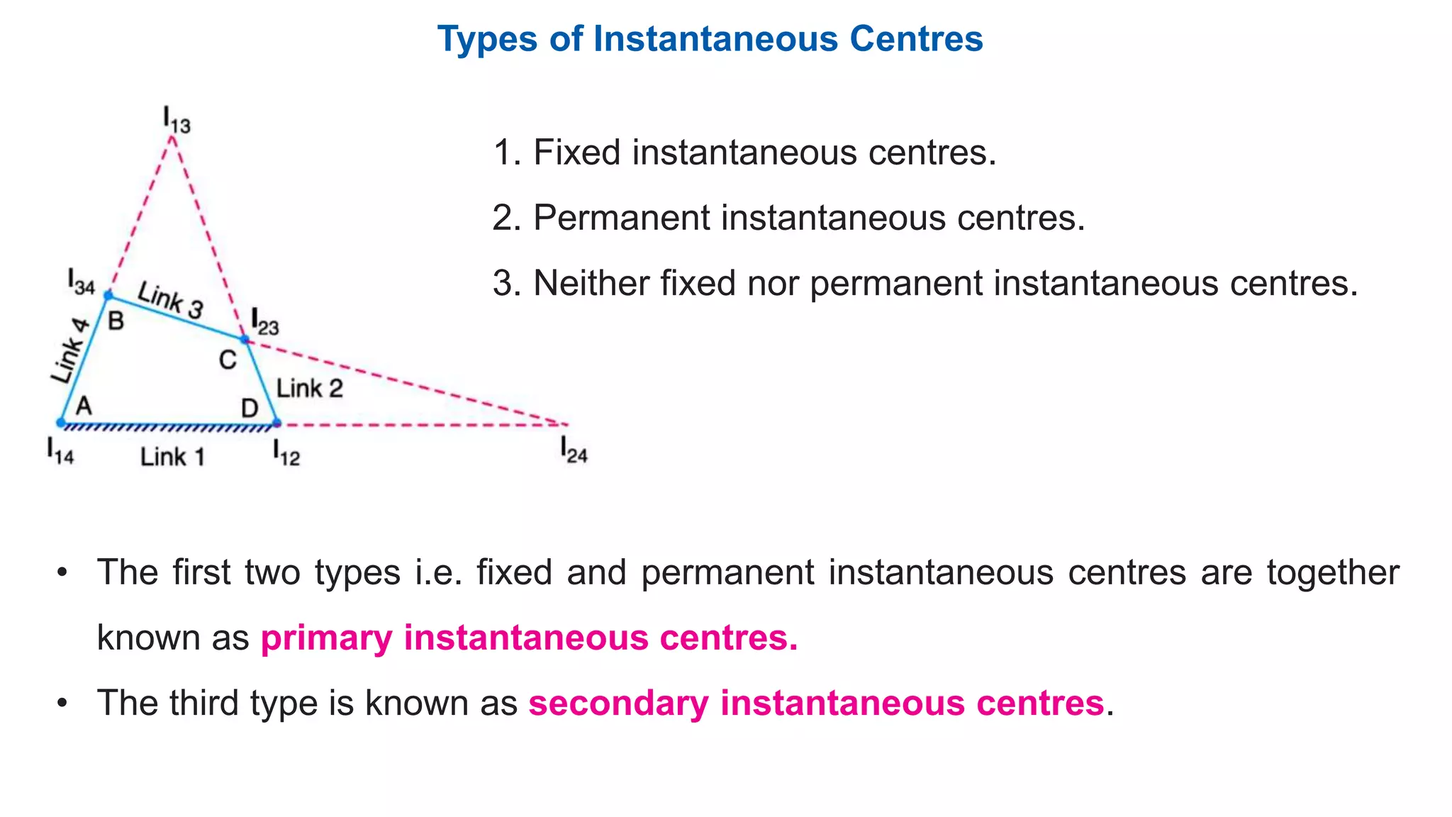
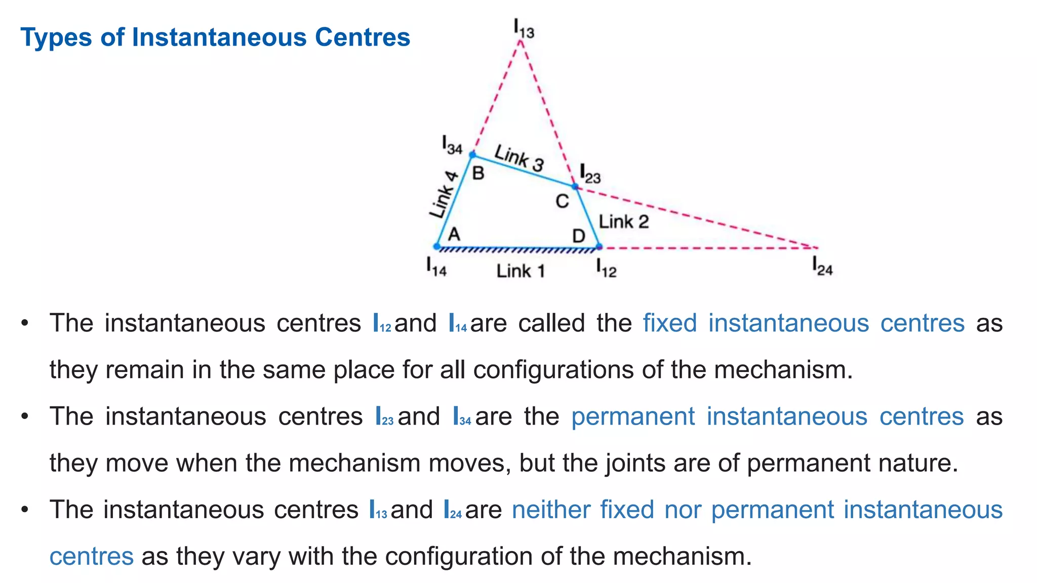
![3. Locate the fixed and permanent instantaneous centres by inspection. In Fig. I12
& I14 are fixed instantaneous centres & I23 and I34 are permanent instantaneous
centres.
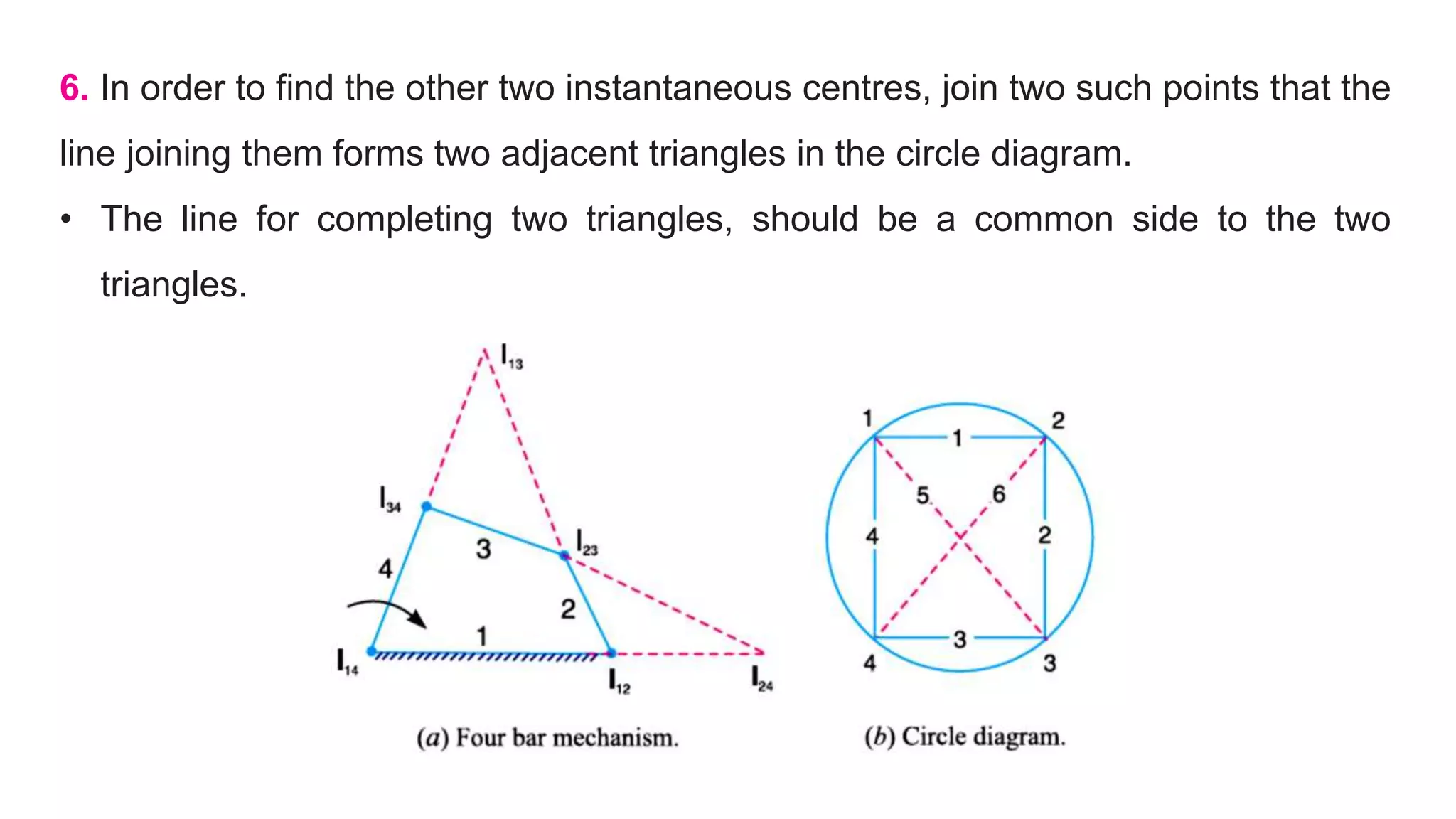
4. Locate the neither fixed nor permanent instantaneous centres by Kennedy’s
theorem. This is done by circle diagram as shown in Fig. (b).
• Mark points on a circle equal to the number of links in a mechanism. In the
present case, mark 1, 2, 3, and 4 on the circle.
5. Join the points by solid lines to show that these centres are already found.
• In the circle diagram [Fig. 6.8 (b)] these lines are 12, 23, 34 and 14 to indicate the
centres I12, I23, I34 and I14.](https://image.slidesharecdn.com/module2instantenouscentermethod-190328033922/75/Module-2-instantenous-center-method-24-2048.jpg)
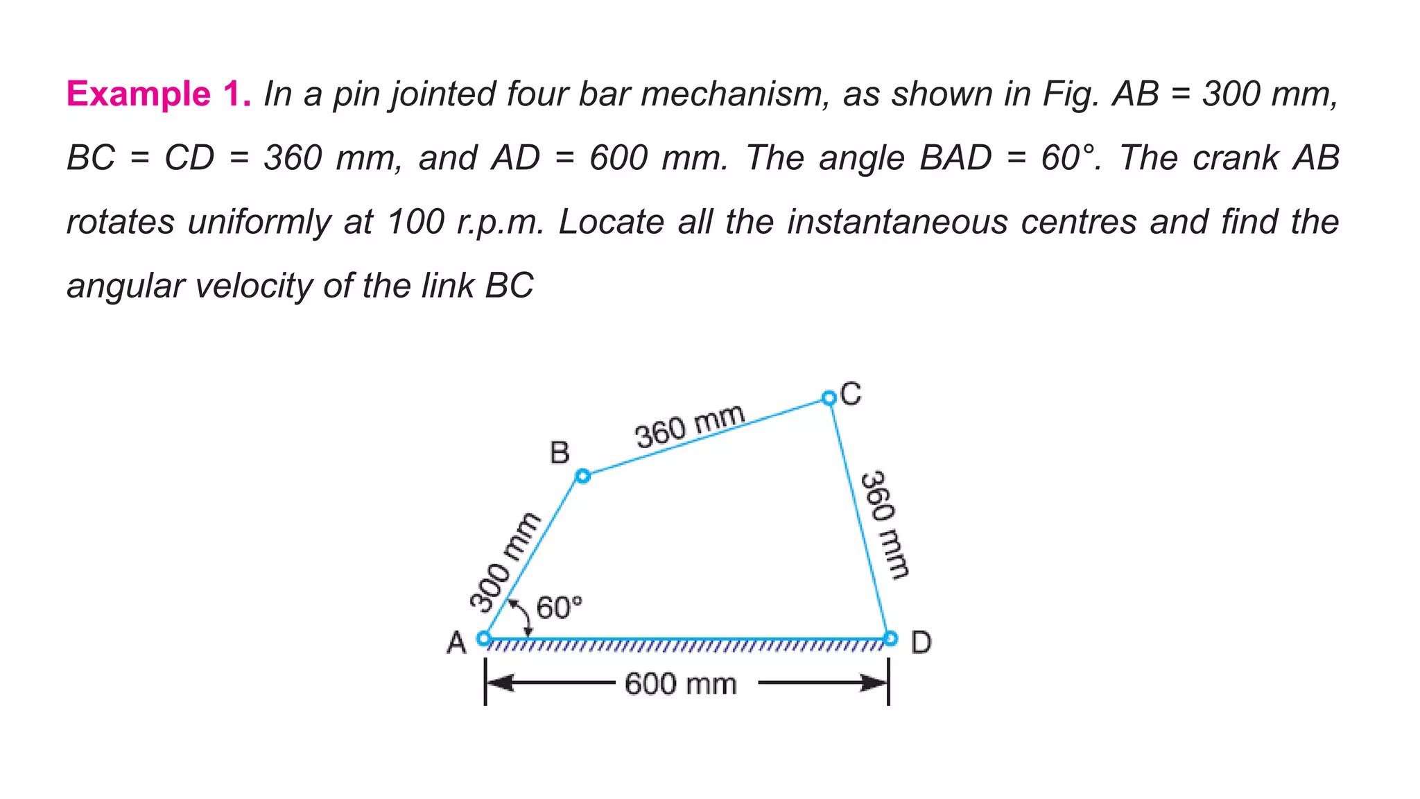

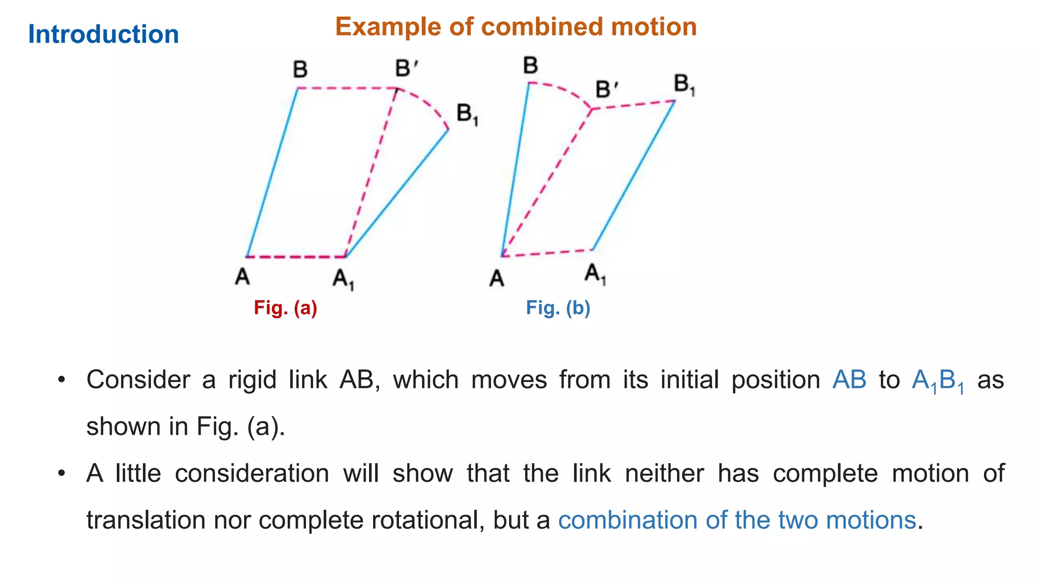
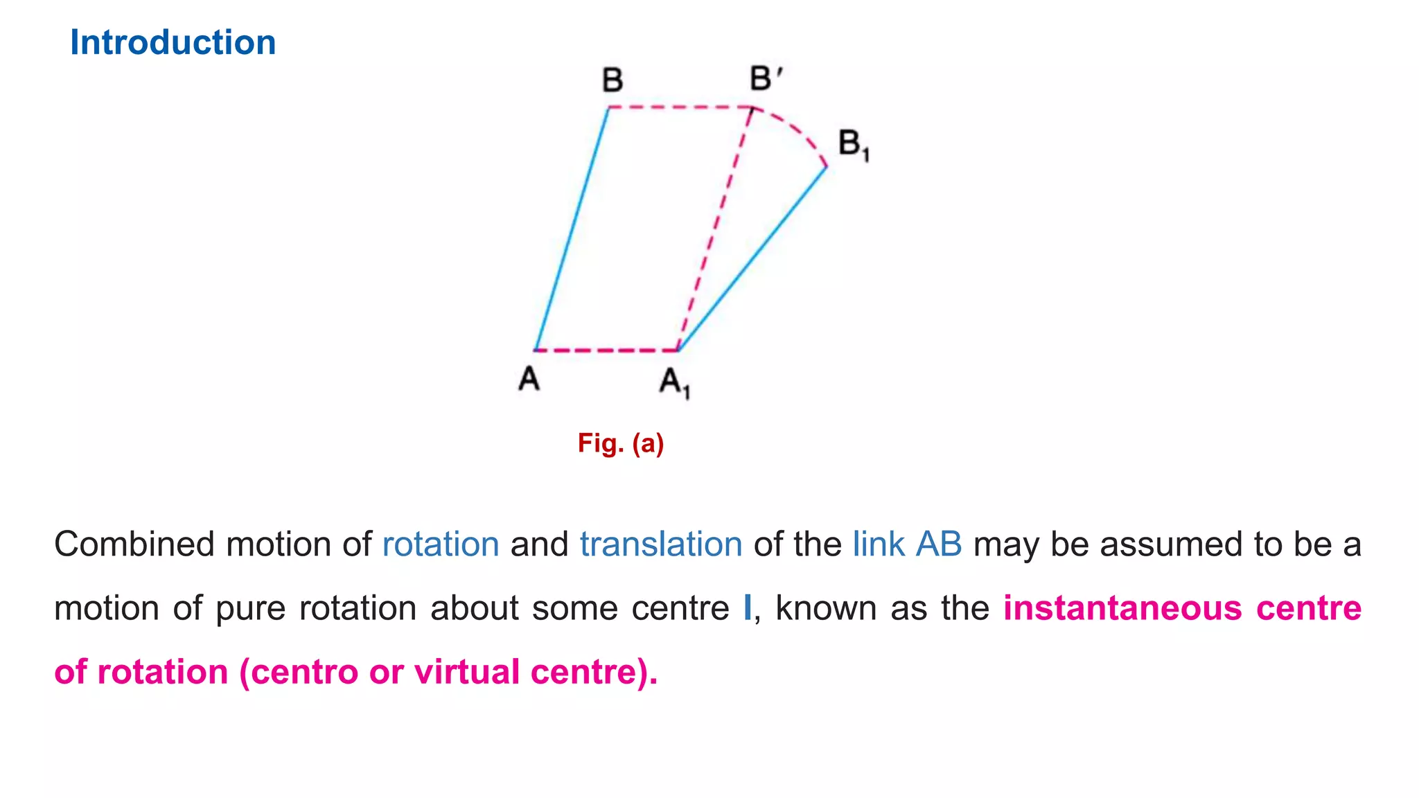
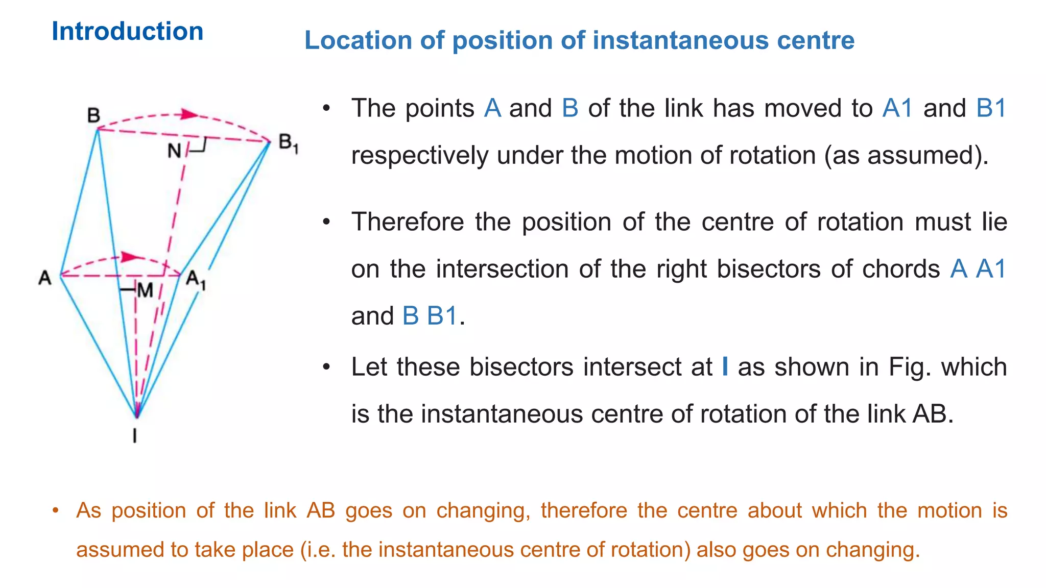
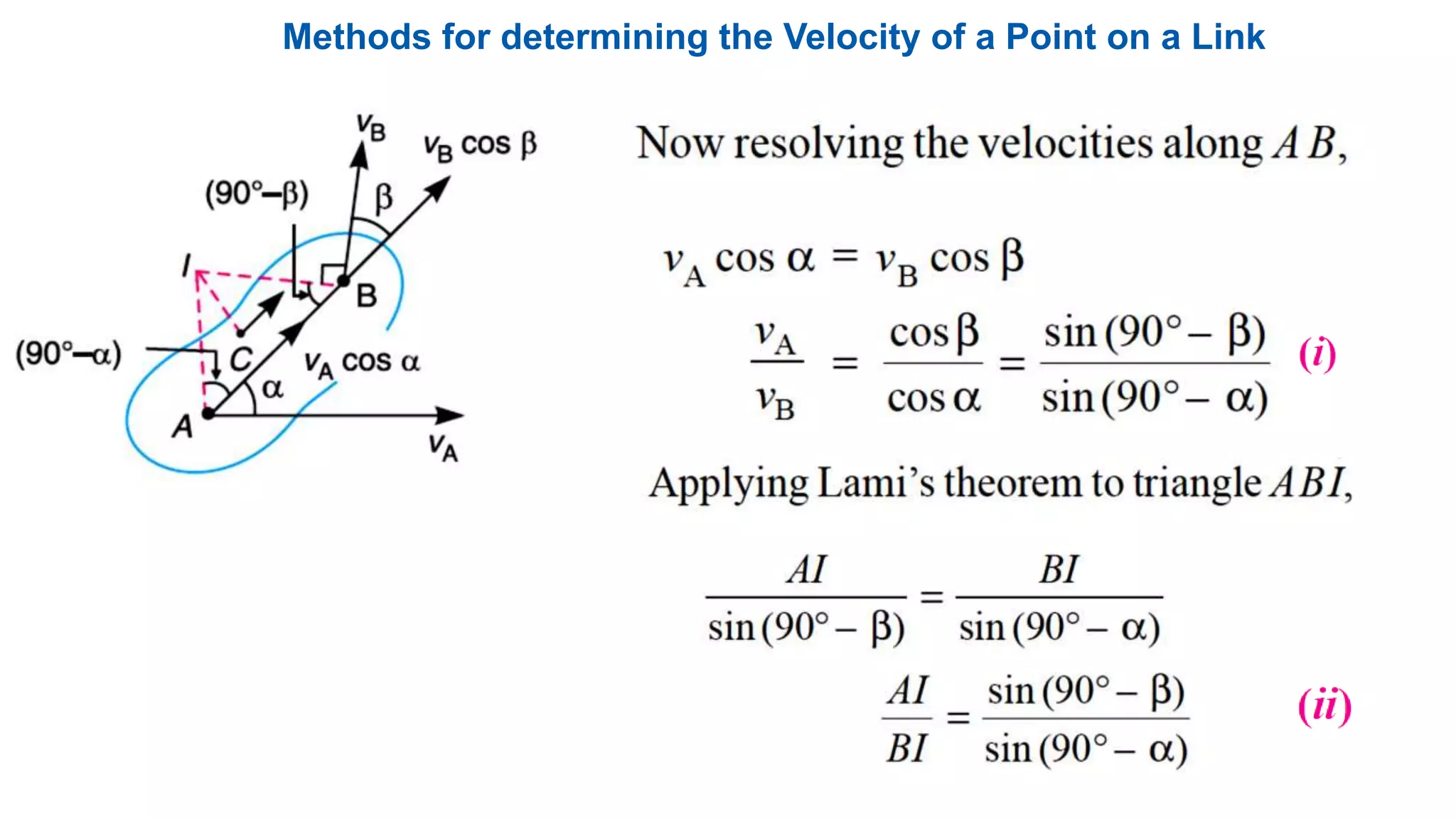
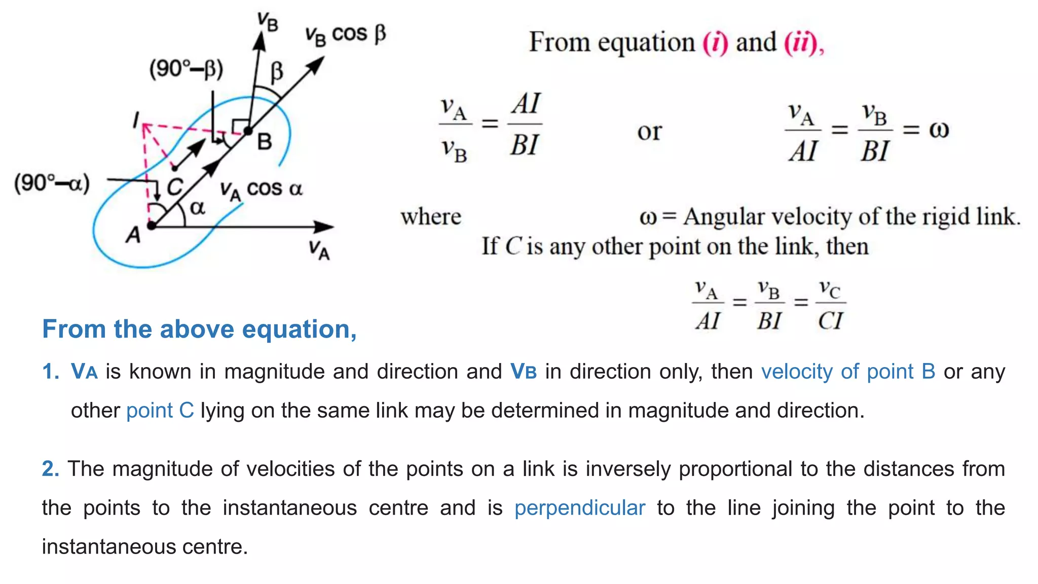
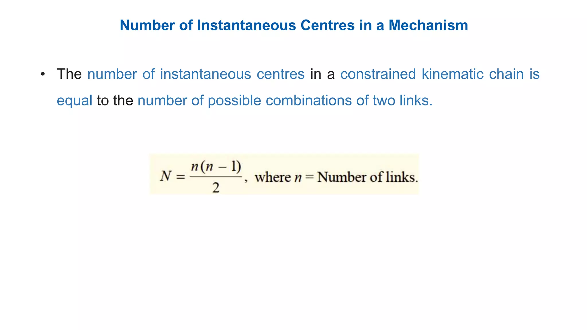
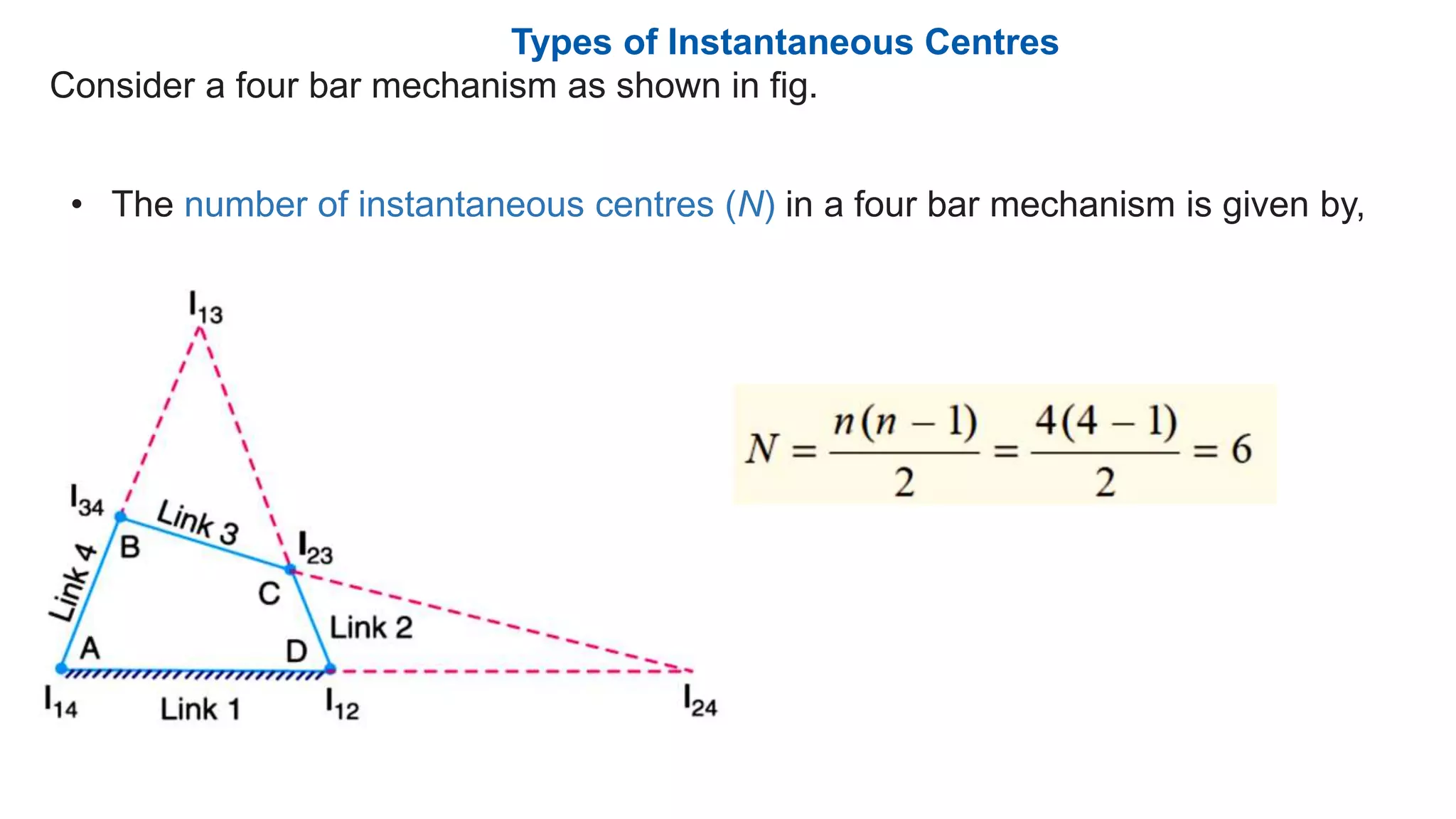
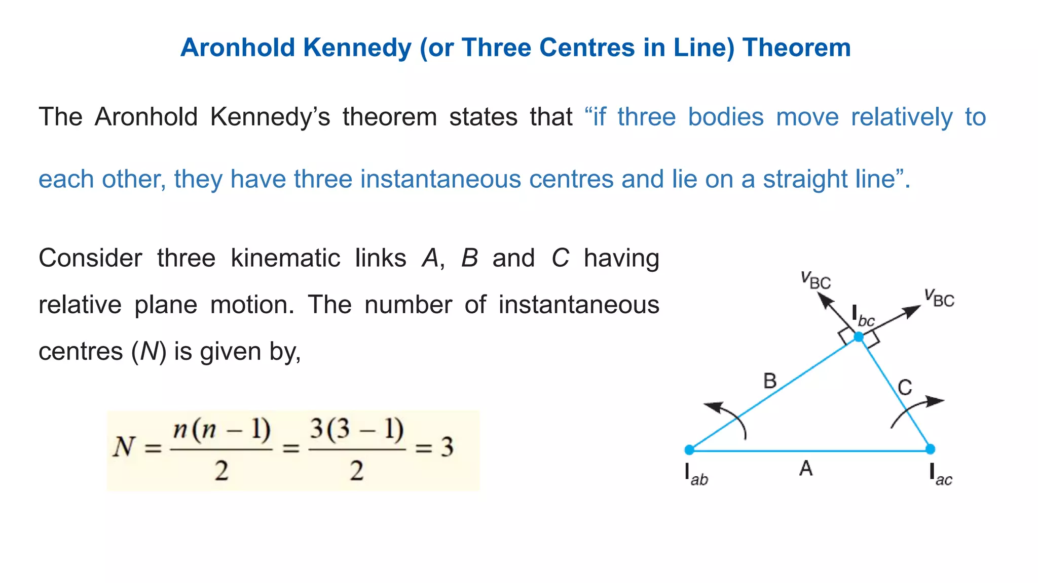
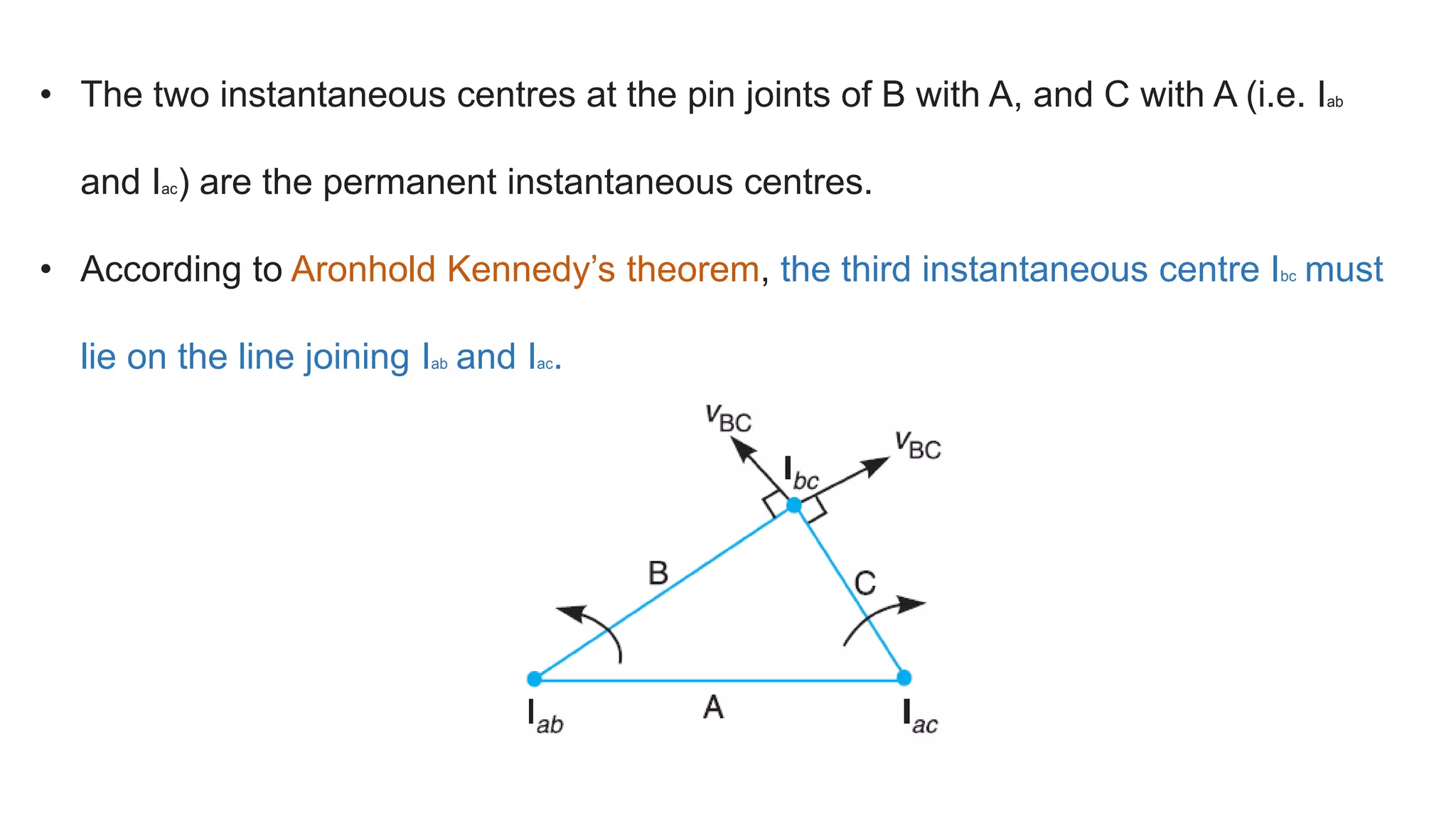
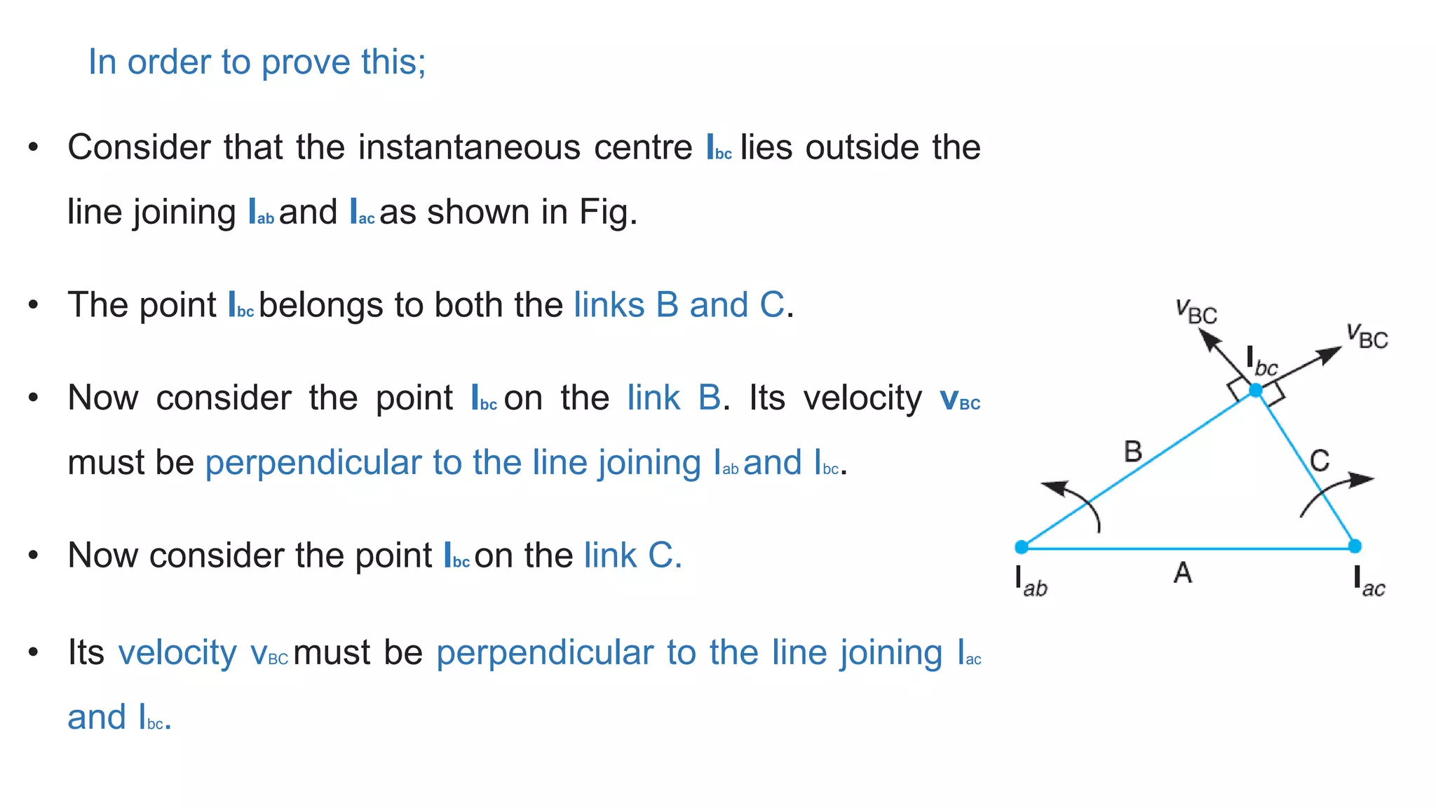
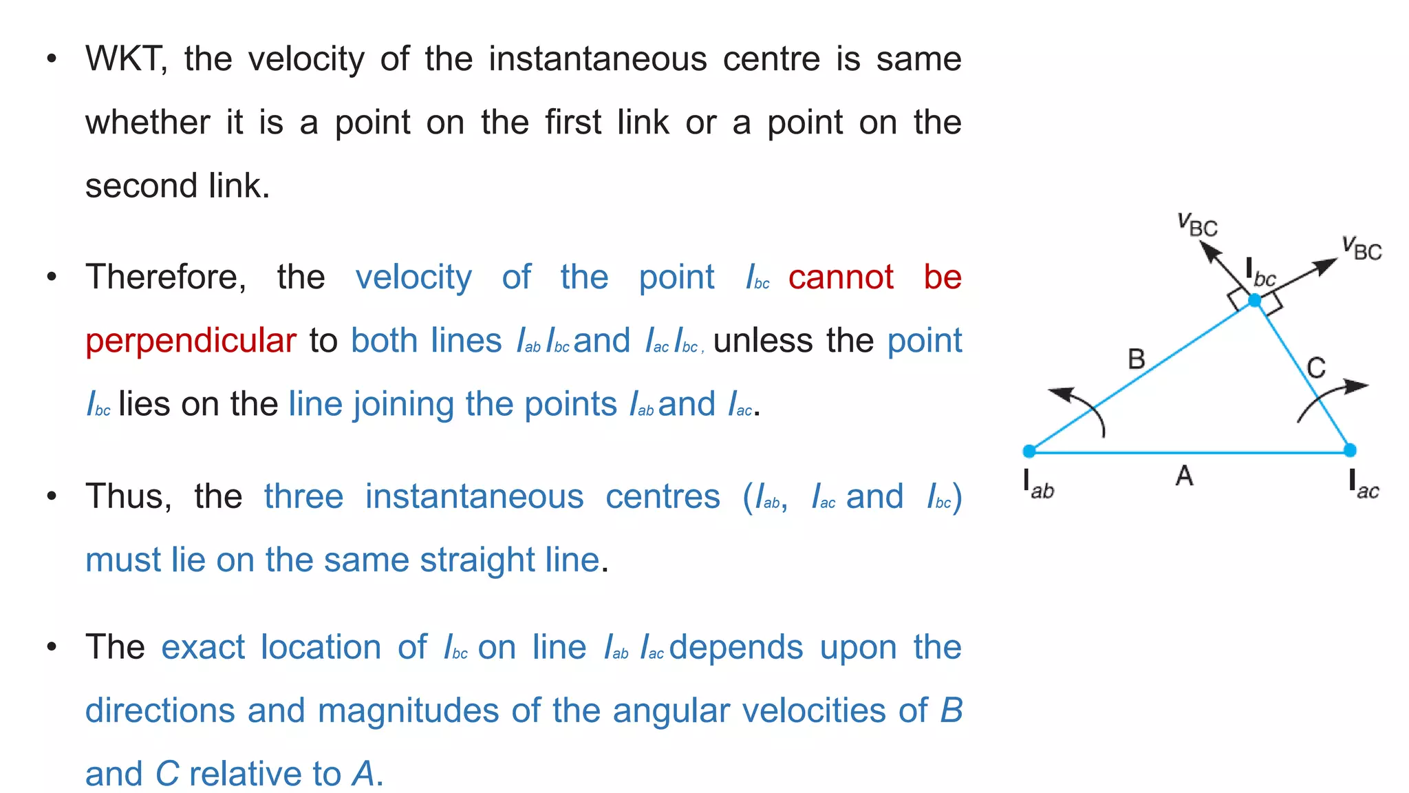
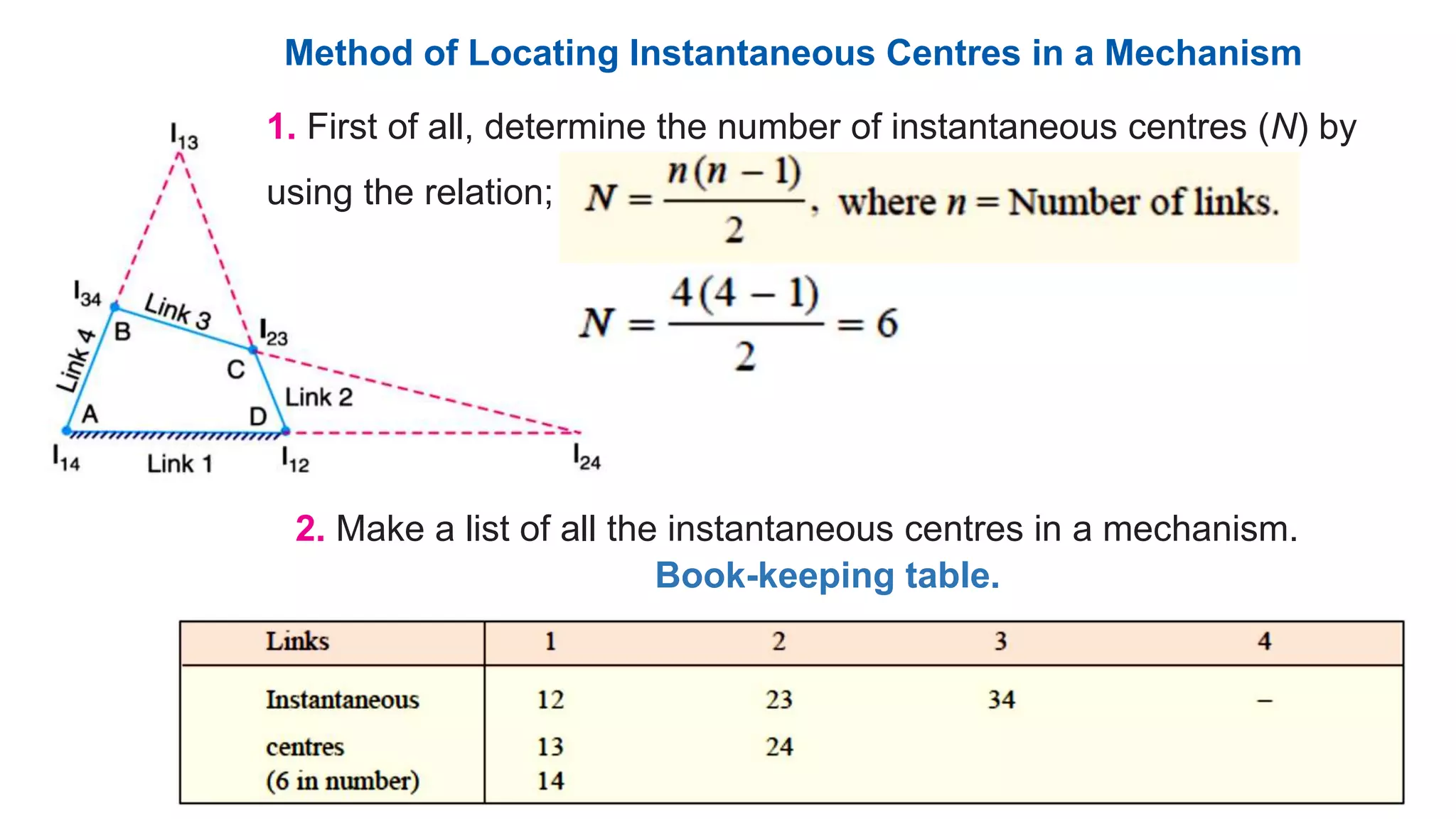
This document discusses instantaneous centers and their application in mechanisms. It begins by defining an instantaneous center as the point about which pure rotational motion can be assumed for a link undergoing combined translation and rotation. It describes how to locate instantaneous centers based on the bisectors of chords formed by the initial and final positions of links. The document outlines different types of instantaneous centers and provides rules for their location in various joint configurations. It introduces the Aronhold-Kennedy theorem stating that three bodies in relative plane motion will have three instantaneous centers collinear on a straight line. Methods for determining the velocity of points on links and locating all instantaneous centers in a mechanism are presented. An example problem is given to locate


![Mechanics of machinery [Recovered].pptx](https://cdn.slidesharecdn.com/ss_thumbnails/mechanicsofmachineryrecovered-220808081831-415b3c97-thumbnail.jpg?width=640&height=640&fit=bounds)