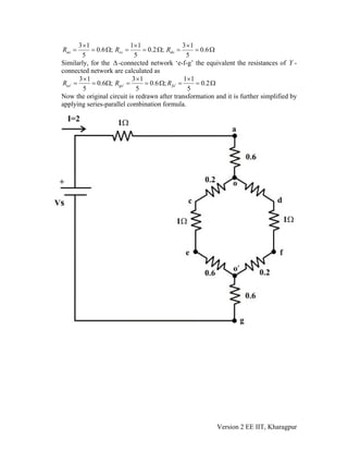
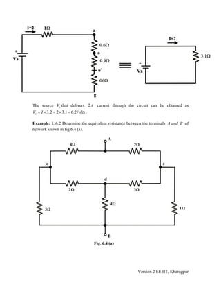
1) The document discusses transformations between Delta (Δ) and Wye (Y) circuit configurations through mathematical relationships.
2) Equations are derived to calculate the resistances of an equivalent Y network given the resistances of a Δ network, and vice versa.
3) Examples demonstrate using the Δ-Y and Y-Δ transformations to simplify circuits and calculate values like total resistance between two points and the input resistance of a circuit.

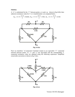

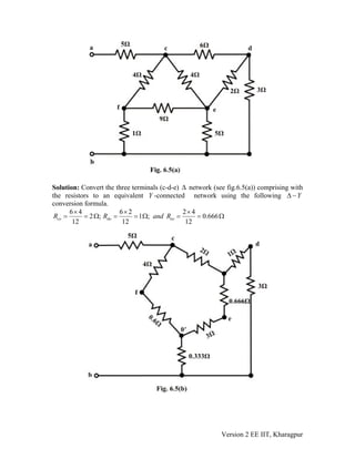
![Simplified form of the circuit is drawn and shown in fig.6.5(d) and one can easily find
out the equivalent resistance between the terminals ‘a’ and ‘b’ using the series-
parallel formula. From fig.6.5(d), one can write the expression for the total equivalent
resistance at the terminals ‘a’ and ‘b’ as
eqR
eqR
( ) ( )
[ ] ( )
5 4.6 || 7.5 0.333||15 ||8.18
5 2.85 0.272 ||8.18 5 3.122 ||8.18
7.26
eqR ⎡ ⎤= + +⎣ ⎦
= + + = +
= Ω
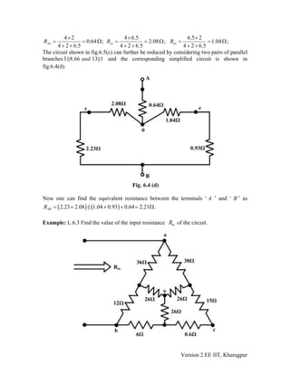
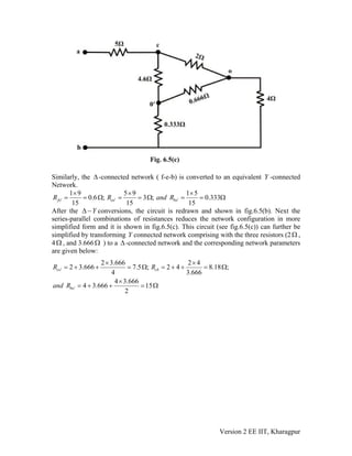
L.6.3 Test Your Understanding [Marks: 40]
T.1 Apply transformations only to find the value of the Current that
drives the circuit as shown in fig.6.6. [8]
Y or Y− Δ Δ − I
Version 2 EE IIT, Kharagpur](https://image.slidesharecdn.com/star-delta-200329070619/85/Star-delta-19-320.jpg)
![(ans: 10.13 )Ω
T.2 Find the current throughI 4Ω resistor using Y − Δ or YΔ − transformation
technique only for the circuit shown in fig.6.7. [10]
(ans: 7.06 A )
T.3 For the circuit shown in fig.6.8, find without performing any conversion. [4]eqR
(Ans.6 )Ω
Version 2 EE IIT, Kharagpur](https://image.slidesharecdn.com/star-delta-200329070619/85/Star-delta-20-320.jpg)
![T.4 For the circuit shown in fig.6.9, calculate the equivalent inductance for each
circuit and justify your answer conceptually. [6]
eqR
(ans. )1 2eq eqR R=
T.5 Find the value of for the circuit of fig.6.10 when the switch is open and when
the switch is closed. [4]
eqR
(Ans. ; )8.75eqR = Ω 7.5eqR = Ω
T.6 For the circuit shown in fig.6.11, find the value of the resistance ‘ ’ so that the
equivalent capacitance between the terminals ‘a’ and b’ is 20.
R
57Ω . [6]
(Ans.30 )Ω
Version 2 EE IIT, Kharagpur](https://image.slidesharecdn.com/star-delta-200329070619/85/Star-delta-21-320.jpg)
![T.7 conversion is often useful in reducing the ------------ of a resistor
network ---------- to the beginning nodal or mesh analysis. [1]
Y or Y− Δ Δ −
T.8 Is it possible to find the current through a branch or to find a voltage across the
branch using conversions only? If so, justify your answer. [1]/Y − Δ Δ −Y
___________________________________________________________
Version 2 EE IIT, Kharagpur](https://image.slidesharecdn.com/star-delta-200329070619/85/Star-delta-22-320.jpg)


