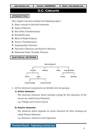
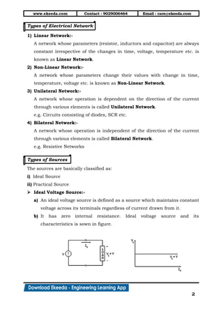
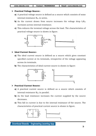
Electronics and Communication Engineering is the Branch of Engineering. Electronics and Communication Engineering field requires an understanding of core areas including Engineering Graphics, Computer Programming,Electronics Devices and Circuits-I, Network Analysis, Signals and Systems, Communication Systems, Electromagnetics Engineering, Digital Signal Processing, Embedded Systems, Microprocessor and Computer Architecture. Ekeeda offers Online Mechanical Engineering Courses for all the Subjects as per the Syllabus.
https://ekeeda.com/streamdetails/stream/Electronics-and-Communication-Engineering
The document discusses star and delta connections that are commonly used in electrical power systems. Star connections are generally used for long distance transmission lines as insulation requirements are less. Delta connections are commonly used in distribution networks for shorter distances. Alternators, generators, and transformer windings can be connected in star or delta configurations. Star-delta transformations allow complex circuits to be simplified by converting between these connection types.
The document discusses alternating current (AC) and provides details about its key characteristics:
1) AC electricity alternates direction periodically in a back-and-forth motion, unlike direct current which flows in one direction.
2) The instantaneous value of AC varies sinusoidally over time between a maximum and minimum value.
3) Common applications of AC include power transmission and use in homes/businesses due to advantages like easy voltage transformation.
The document discusses the efficiency of transformers. It notes that transformer efficiency is measured as the ratio of output to input power. Losses include copper and iron losses, with iron losses dependent on load. For distribution transformers with varying daily loads, all-day efficiency is measured, which accounts for the transformer's capability over the full day and is always lower than commercial efficiency measured at a single time.
1) DC generators convert mechanical energy to electrical energy through Faraday's law of electromagnetic induction. When a conductor moves through a magnetic field, an EMF is induced in the conductor.
2) The main components of a DC generator are the yoke, field electromagnets, armature, commutator, and brushes. The armature is wound with coils and rotates within the magnetic field produced by the field electromagnets to generate an EMF.
3) As the armature rotates, the commutator and brushes are used to periodically reverse the direction of current in the external circuit, thereby producing direct current. Losses in the generator arise from copper, iron, and mechanical components
1. A transformer is a device that converts alternating current (AC) of one voltage to another voltage without changing the frequency. It consists of coils wrapped around a common core and uses electromagnetic induction.
2. Nikola Tesla proposed using transformers to increase voltage for efficient power transmission over long distances, then step it back down for safe distribution and use. This system replaced the inefficient direct current system developed by Edison.
3. Transformers allow efficient transmission of power by reducing current and thus transmission losses, while maintaining the same power level. They are essential components for modern power distribution systems.
The document discusses capacitors and capacitance. It defines a capacitor as a device that stores electrical charge between two parallel plates and defines capacitance as the ability of a capacitor to store energy in the form of electric charge. It describes different types of capacitors including fixed, polarized, and variable capacitors. It also discusses how capacitors work by storing energy electrostatically in an electric field and how capacitors can be connected in series and parallel. Finally, it lists some common applications of capacitors such as in radio tuners, AC circuits, computer circuits, camera flashes, and AC/DC converters.
1) HVDC transmission was first developed in the late 19th century by Rene Thury. Early systems used DC series generators and mechanical converters.
2) HVDC became more viable with the development of mercury arc valves in the 1950s and thyristor valves in the 1960s, allowing more efficient conversion between AC and DC.
3) HVDC is preferable to HVAC for long distance bulk power transmission, asynchronous connections, offshore wind connections, and other applications where HVDC has technical advantages over HVAC. Key components of HVDC systems include converters, smoothing reactors, filters, and the DC transmission line.
Electric cells convert chemical energy into electrical energy to produce electricity. Multiple cells connected together form a battery. Batteries produce a potential difference across their terminals through chemical reactions, providing energy to move electrons through an external circuit. The electromotive force (emf) of a battery is the voltage when no current flows, while internal resistance causes voltage to drop under load. Batteries can be connected in series, where the total emf is the sum of individual cells and current is the same through each, or in parallel, where the total current is the sum of individual cells and voltage is the same across each.
1) The document discusses the generation of alternating current using a single-turn alternator with a rotating coil within a magnetic field.
2) As the coil rotates, an alternating voltage is induced based on Faraday's law of electromagnetic induction. The magnitude of the induced voltage depends on the angle of rotation and reaches its maximum when the coil is perpendicular to the magnetic field lines.
3) The instantaneous induced voltage can be expressed as a sinusoidal function of the angle of rotation, with the maximum voltage achieved at 90° of rotation. This generates an alternating current through a load that also follows a sinusoidal pattern.
This document discusses the history and characteristics of alternating current (AC). It explains that AC electricity is generated by an AC electric generator and flows first in one direction and then the other, unlike direct current. Some key advantages of AC are that it can be transformed between voltages and controlled by various circuit components. The document also covers concepts such as reactance, impedance, and phase relationships in AC circuits. It describes how AC behaves differently than DC in capacitors and inductors due to the changing current.
AC or alternating current periodically reverses direction, while DC flows in one direction. AC is widely used because it can be easily produced and transformed. The RMS or root mean square value provides the equivalent DC value that would produce the same average power output as the AC value. RMS values are what voltmeters and ammeters read for AC circuits. Rectification converts AC to DC using diodes in a bridge configuration.
1) Effective current in an AC circuit is 0.707 times the maximum current. Effective voltage is 0.707 times the maximum voltage.
2) Inductive reactance is directly proportional to frequency and inductance. Capacitive reactance is inversely proportional to frequency and capacitance.
3) Impedance is the total opposition to current flow in an AC circuit consisting of resistance and reactance. Power is consumed only by the resistive component of impedance and is proportional to the cosine of the phase angle.
The document describes the main construction of DC machines. It lists the two major parts as the stator, which houses the field winding, and the rotor, which rotates in the magnetic field. It then describes the other key parts which include the yoke, poles, field winding, armature winding, commutator, and brushes. The yoke forms a protective covering and carries magnetic flux. The poles contain core and shoe components that produce magnetic flux. The field and armature windings use copper wire to generate electromagnetism. The commutator collects alternating current from the armature and converts it to direct current, while the brushes collect this current.
The document discusses magnetic hysteresis curves (B-H curves) of ferromagnetic materials. It explains that B-H curves plot the flux density (B) versus the field strength (H) and show how B increases with H until saturation. The curves also demonstrate retentivity, where some residual magnetism remains after H is removed. Drawing the full curve as H is cycled from positive to negative produces a magnetic hysteresis loop. The size of the loop indicates the energy lost to hysteresis during the cycling of H. Materials with smaller loops incur lower hysteresis losses and are preferred for applications with frequent field reversals like transformer cores.
This document discusses polyphase circuits, including:
1. Polyphase circuits have multiple phases or windings that produce voltages displaced by equal electrical angles. Three-phase systems produce three voltages displaced by 120 degrees.
2. Star and delta connections are used to interconnect the phases. In a star connection, line voltage is 3 times phase voltage and line current equals phase current. In a delta connection, line voltage equals phase voltage and line current is 3 times phase current.
3. Three-phase systems have advantages over single-phase like constant power, greater output, cheaper transmission, and easier rectification for DC power.
The document describes the construction and working of a moving coil galvanometer, which is a device used to detect or measure electric current. It consists of a coil of wire suspended in a uniform magnetic field provided by a horseshoe magnet. When current passes through the coil, it experiences a torque and deflects from the magnetic field. The angle of deflection is directly proportional to the current. The coil is attached to a light spring which provides a restoring torque as the coil deflects, bringing it back to the center when the currents are removed. The current and voltage sensitivities can be increased by modifying parameters of the coil and spring.
Three-phase systems have multiple voltages or currents that are displaced in time by 120 degrees. They provide advantages over single-phase systems like higher power capacity, self-starting motors, and more constant power output.
A 3-phase generator produces 3 voltages displaced by 120 degrees through its winding configuration. The voltages can be connected in either a star or delta configuration. In a star connection, the winding ends meet at a central neutral point. In a delta connection, the windings are connected in a closed loop.
Power in a 3-phase circuit can be measured using either 3 wattmeters connected to each phase, or 2 wattmeters connected across different phase combinations to calculate total power.
This ppt describes about,
introduction of fuses, construction, Important terms, advantages and disadvantages, desirable characteristics of fuse element, Current time characteristics, Fuse types - Low voltages fuses and High voltage fuses, Semi enclosed rewirable fuse, HRC cartridge fuses - parts, operation, pros and cons, High voltage fuses and its types, selection of fuses, discrimination
This document provides information about transformers, including their components, principles of operation, and applications. It discusses how transformers transfer electrical energy from one circuit to another through electromagnetic induction, changing the voltage and current magnitudes but not the frequency. The key components are the core, primary winding, and secondary winding. Transformers operate based on the principle of mutual induction between the windings. They are used in various applications like power transmission and audio/radio frequencies.
The document discusses various types of tests conducted on isolators, bushings, cables, and circuit breakers. Key tests include:
1. Power frequency and impulse voltage withstand tests to check the insulation strength of isolators, bushings, and cables.
2. Partial discharge and tan delta tests to evaluate insulation condition and dielectric losses.
3. Short circuit tests on circuit breakers to check their ability to safely interrupt fault currents under different voltage and current conditions.
4. Other tests include temperature rise, mechanical endurance, and measurement of electrical characteristics.
This document discusses magnetic circuits and electromagnetic induction. It defines key terms like magnetic flux, magnetomotive force, reluctance, self-inductance, and mutual inductance. Faraday's laws of induction state that an electromotive force (EMF) is induced in a coil when the magnetic flux through the coil changes. Lenz's law specifies that the induced EMF will oppose the change that created it. Magnetic circuits can be modeled similarly to electric circuits, with magnetomotive force, magnetic flux, and reluctance analogous to voltage, current, and resistance.
The document discusses transformer ratings, efficiency, and power factor. It explains that transformers are rated in kVA rather than kW because manufacturers do not know the load power factor in advance. Maximum efficiency occurs when iron losses equal copper losses. Transformer efficiency is calculated based on output power in watts rather than volt-amperes. Low power factor reduces efficiency by decreasing the output power relative to losses. Correcting power factor can help increase efficiency when a transformer is overloaded.
the ratio of the actual electrical power dissipated by an AC circuit to the product of the r.m.s. values of current and voltage. The difference between the two is caused by reactance in the circuit and represents power that does no useful work.
1) Capacitance is a measure of the amount of electric charge stored on a conductor for a given potential difference between conductors. The capacitance of a parallel plate capacitor is directly proportional to the area of its plates and inversely proportional to the distance between the plates.
2) When capacitors are connected in parallel, the equivalent capacitance is the sum of the individual capacitances. In series, the equivalent capacitance is less than the individual capacitances.
3) Energy is stored in a capacitor when it is charged, and this energy can be rapidly discharged. Capacitors are used in applications where energy must be stored and quickly released, such as in defibrillators.
This document discusses reactive power compensation in power systems. It defines reactive power as power that is temporarily stored and returned to the source due to inductive loads. Reactive power compensation is needed to improve power factor, reduce losses, improve voltage regulation and stability. The main compensation techniques discussed are synchronous condensers, shunt compensation using capacitors connected in parallel, and series compensation using capacitors connected in series to reduce line inductive reactance. The document provides examples of transmission lines with shunt and series compensation and concludes that reactive power compensation is important for improving AC system performance.
EMF EQUATION OF DC GENERATOR,DC MOTOR|DAY15|BACK EMF,TORQUE OF DC MOTOR|BASIC...Prasant Kumar
#EMF EQUATION OF DC GENERATOR
#EMF EQUATION OF DC MOTOR
#TORQUE EQUATION OF DC MOTOR
# EMF EQUATION OF DC MOTOR IN HINDI
#DERIVATION OF DC MOTOR EMF EQUATION
#FARADAY LAW OF ELECTROMAGNETIC INDUCTION
#back emf in dc motor
#back emf in dc motor in hindi
In this video you will learn about,derivation of dc machine emf equation,back emf,torque equation of dc motor,dc generated,dc motor.To understand electrical machine with trick watch all videos,
MUST UPGRADE YOUR KNOWLEDGE BY FLIPPED LEARNING
#Topic - ELECTRICAL TRANSFORMER
~ Link of all sessions are.
DAY 1 (Need/Definition)
https://youtu.be/BvaykFJ_NoE
DAY 2 (Working principle and Construction)
https://youtu.be/06rgxocihaM
DAY 3 (EMF equation and Turns Ratio)
https://youtu.be/g7e5xBPmv3Y
DAY 4 (Classification of Transformer)
https://youtu.be/6NP5L4MlvY4
DAY 5 ( Ideal and practical transformer on no load)
(Equivalent Transformer)
https://youtu.be/6LCLQC1p3lg
DAY 6 ( Losses in Transformer)
https://youtu.be/ObYNiGgd3hA
DAY 7 (O.C. and S.C. test)
https://youtu.be/8WiJRawHiTce/6LCLQC1p3lg
DAY 8 (Voltage Regulation & Efficiency)
https://youtu.be/6LCLQC1p3lg
DAY 9 (Zero Lecture)
https://youtu.be/N4xWOwgi8I4
DAY 10 (Classification of machine)
https://youtu.be/bmxnU5rC5m4
Construction of Machine
https://youtu.be/34mpphDk3gg
Working Principle of Synchronous Generator & Synchronous Motor
https://youtu.be/bkgf72M8BCY
Working Principle of Induction Motor
https://youtu.be/Lj_iQBoRiK0
Ekeeda Provides Online Electrical and Electronics Engineering Degree Subjects Courses, Video Lectures for All Engineering Universities. Video Tutorials Covers Subjects of Mechanical Engineering Degree. Visit us: https://ekeeda.com/streamdetails/stream/Electrical-and-Electronics-Engineering
The document provides an overview of topics related to electrical circuits and electromagnetism including:
1) Definitions of key circuit elements and analysis techniques like Kirchhoff's laws, superposition theorem, and Thevenin's theorem.
2) Concepts in electromagnetism including Biot-Savart law, Ampere's law, Faraday's law, and magnetic circuits.
3) Analysis of AC circuits including waveform properties, phasor representation, and resonance in RLC circuits.
This document provides an overview of basic electrical concepts and circuit analysis for engineering students. It covers topics like voltage and current sources, Kirchhoff's laws, Thevenin's and superposition theorems, AC circuits including power calculations, and three-phase systems. The key points are:
1) It defines fundamental electrical terms and describes different types of sources and circuit analysis methods like mesh and nodal analysis.
2) Kirchhoff's laws are introduced for analyzing circuits using the concepts of current law and voltage law.
3) Thevenin's and superposition theorems are summarized as techniques for simplifying circuits with multiple sources.
4) Single-phase AC circuits are covered including definitions
This document discusses electrical current, current density, resistivity, resistance, and circuit analysis using Kirchhoff's laws. It provides examples of calculating current, resistance, voltage, and power in series, parallel, and combination circuits. Key points covered include:
- Definitions of current, current density, resistivity, resistance, and their units
- Relationships between current density, current, area, and resistance
- Kirchhoff's junction and loop rules for analyzing circuits
- Examples of using the junction and loop rules to solve for unknown currents, voltages, and resistances in various circuits.
This document outlines various circuit analysis techniques including mesh analysis, nodal analysis, and network theorems. Section 1 discusses methods of analysis such as source conversion, mesh analysis using both general and format approaches, and nodal analysis using general and format approaches. Section 2 covers network theorems including superposition theorem, which is used to solve circuits by calculating the effect of individual sources and adding them together. Choosing an analysis method depends on whether the circuit has fewer meshes or nodes, as the goal is to generate the fewer simultaneous equations.
An electric circuit is a path in which electrons from a voltage or current source flow. The point where those electrons enter an electrical circuit is called the "source" of electrons.
1) Nodal analysis is a circuit analysis technique that uses node voltages as variables. It involves applying Kirchhoff's Current Law (KCL) at each node to obtain equations relating the node voltages.
2) To perform nodal analysis, a reference node is selected and assigned a voltage of 0 V. Voltages of other nodes are assigned with respect to the reference node. Then, KCL is applied at each non-reference node to obtain equations.
3) Ohm's law is used to express branch currents in terms of node voltages. This results in a system of simultaneous equations that can be solved for the unknown node voltages.
This document provides an overview of equivalent circuits and circuit analysis techniques including node-voltage analysis, mesh analysis, and dealing with dependent and independent sources. It defines equivalent circuits as circuits that can replace one another without changing the external behavior of the overall circuit. It also describes node-voltage and mesh analysis, specifying how to write equations for each method by applying Kirchhoff's laws. Techniques for handling dependent sources and circuits with no path to ground are discussed. Examples demonstrate transforming between delta-wye configurations and using the different analysis methods to solve for voltages and currents.
Electrical elements are conceptual abstractions representing idealized electrical components, such as resistors, capacitors, and inductors, used in the analysis of electrical networks. All electrical networks can be analyzed as multiple electrical elements interconnected by wires.
1) The document discusses DC fundamentals and circuits, covering topics like charge, current, voltage, power, energy, Ohm's law, and Kirchhoff's laws. It also covers basic circuit analysis using these principles.
2) Key concepts discussed include the definitions of current, voltage, resistance, and time constants. Kirchhoff's laws and Ohm's law are also summarized.
3) Examples are provided to demonstrate using these principles to solve circuits for unknown currents and voltages. Circuit analysis techniques like mesh current analysis and nodal voltage analysis are also mentioned.
Sesión de Laboratorio 3: Leyes de Kirchhoff, Circuitos RC y DiodosJavier García Molleja
Laboratory session in Physics II subject for September 2016-January 2017 semester in Yachay Tech University (Ecuador). Topic covered: electricity, electrical circuits, resistances, capacitances, diodes
Based on Bruna Regalado's work
This document provides information about basic circuit analysis and network topology. It defines key concepts like Ohm's law, Kirchhoff's laws, ideal sources, potential, graphs, trees, cut-sets, incidence matrices, and more. It also lists questions that assess understanding of these topics, network theorems for DC and AC circuits, resonance in RLC circuits, and coupled circuits.
Dependent sources behave like independent voltage and current sources, except that their voltage or current depends on another voltage or current in the circuit. There are four types of dependent sources: voltage-controlled voltage source, current-controlled voltage source, voltage-controlled current source, and current-controlled current source. Circuit analysis proceeds similarly to circuits with independent sources, though source transformations must be used carefully with dependent sources.
This document contains an exam for an Electrical Circuits course, with two parts and five units. Part A contains 10 short answer questions covering various circuit analysis topics like transformations, inductance calculations, power factors, and Fourier transform properties. Part B contains longer problems and explanations across five units: Kirchhoff's laws and induction, three-phase systems, network analysis techniques like nodal analysis, network theorems, and transient responses. Sample problems are provided for each unit involving circuit diagrams and calculations of values like currents, voltages, power, and time-domain circuit analysis.
This document provides instructions for an experiment involving Kirchhoff's Current and Voltage Laws. The objectives are to learn and apply Kirchhoff's Current Law and Kirchhoff's Voltage Law, obtain further practice with electrical measurements, and compare results with calculations and simulations. The experiment uses a circuit with four resistors to apply the two Kirchhoff's Laws and calculate voltages and currents at various points. Students are instructed to use the laws to derive equations relating node voltages, solve them through calculation and simulation, measure resistor values, and compare results.
Ekeeda Provides Online Electrical and Electronics Engineering Degree Subjects Courses, Video Lectures for All Engineering Universities. Video Tutorials Covers Subjects of Mechanical Engineering Degree.
This document discusses series and parallel circuits. It defines series and parallel circuits and explains how to calculate total resistance and current in each. In series circuits, total resistance is the sum of individual resistances and current is the same everywhere. In parallel circuits, total resistance is less than individual resistances and total current is the sum of branch currents. The document also provides examples of calculating resistance, current, and voltage in series and parallel circuit problems.
1) The document is a lab manual for an Electrical Engineering measurement lab course. It details 10 experiments involving measuring devices like oscilloscopes, multimeters, and bridges.
2) The first experiment involves studying oscilloscopes, their working principles, and different types of probes. Block diagrams and features of oscilloscopes are described.
3) Power factor is defined as the ratio between real power and apparent power. A power factor meter and phase shifter circuit are explained along with calculations for power factor correction by adding a capacitor.
Elements of electrical engineering dc circuitsHardik Lathiya
This document provides an overview of elements of electrical engineering, including DC circuits. It discusses common circuit elements like resistors, capacitors, and inductors. It describes their properties and symbols used to represent them in schematics. The document also covers resistor networks and how to calculate equivalent resistances for resistors in series and parallel. Kirchhoff's laws and techniques for solving resistor networks like star-delta transformations are presented. Examples of calculating equivalent resistances and currents in circuits are provided.
The document provides an overview of key concepts in electric circuits including:
- Kirchhoff's current and voltage laws, mesh current analysis, nodal voltage analysis, and Thevenin's and maximum power transfer theorems for analyzing DC circuits.
- Basic terminology and concepts for analyzing AC circuits including RMS values, average values for half wave and full wave rectified signals, and fundamentals of single phase and three phase AC systems.
- Practice problems on theorems and examples of half wave and full wave rectifier circuits are also included.
Mechanical Engineering is the Branch of Engineering.The mechanical engineering field requires an understanding of core areas including mechanics, dynamics, thermodynamics, materials science and structural analysis,Fluid Mechanics, Metrology and Instrumentation, Dynamics of Machinery- II, Manufacturing Processes II, Industrial Drafting and Machine Design, Engineering Graphics, Power Plant Engineering. Ekeeda offers Online Mechanical Engineering Courses for all the Subjects as per the Syllabus. Visit us: https://ekeeda.com/streamdetails/stream/mechanical-engineering
Ekeeda Provides Online Video Lectures for Mechanical Engineering Degree Subject Courses for All Engineering Universities. Visit us: https://ekeeda.com/streamdetails/stream/mechanical-engineering
Civil Engineering is the Branch of Engineering.The Civil engineering field requires an understanding of core areas including Mechanics of Solids, Structural Mechanics - I, Building Construction Materials, Surveying - I, Geology and Geotechnical Engineering, Structural Mechanics, Building Construction, Water Resources and Irrigation, Environmental Engineering, Transportation Engineering, Construction and Project Management. Ekeeda offers Online Mechanical Engineering Courses for all the Subjects as per the Syllabus Visit us: https://ekeeda.com/streamdetails/stream/civil-engineering
Ekeeda Provides Online Video Lectures for Civil Engineering Degree Subject Courses for All Engineering Universities. Visit us: https://ekeeda.com/streamdetails/stream/civil-engineering
Kinetics of particles impulse momentum methodEkeeda
Ekeeda Provides Online Video Lectures for Civil Engineering Degree Subject Courses for All Engineering Universities. Visit us: https://ekeeda.com/streamdetails/stream/civil-engineering
Learn Online Courses of Subject Introduction to Civil Engineering and Engineering Mechanics. Clear the Concepts of Introduction to Civil Engineering and Engineering Mechanics Through Video Lectures and PDF Notes. Visit us: https://ekeeda.com/streamdetails/subject/introduction-to-civil-engineering-and-engineering-mechanics
Ekeeda Provides Online Video Lectures for Civil Engineering Degree Subject Courses for All Engineering Universities. Visit us: https://ekeeda.com/streamdetails/stream/civil-engineering
Coplanar forces res & comp of forces - for mergeEkeeda
Ekeeda Provides Online Video Lectures for Civil Engineering Degree Subject Courses for All Engineering Universities. Visit us: https://ekeeda.com/streamdetails/stream/civil-engineering
This document discusses concepts related to static equilibrium of rigid bodies, including:
- Conditions for static equilibrium are that the net force and net moment are both zero
- Free body diagrams show all forces acting on a body in isolation
- Types of supports (fixed, hinge, roller) and the reactions they provide are described
- Concepts like two-force and three-force members, Lami's theorem, and finding equilibrant forces to balance unbalanced systems are explained
- Several example problems are provided to illustrate applying concepts to determine reactions and tensions in static systems
Ekeeda Provides Online Video Lectures for Civil Engineering Degree Subject Courses for All Engineering Universities. Visit us: https://ekeeda.com/streamdetails/stream/civil-engineering
Infomatica, as it stands today, is a manifestation of our values, toil, and dedication towards imparting knowledge to the pupils of the society. Visit us: http://www.infomaticaacademy.com/
1) The document discusses Gibbs phase rule, which relates the number of degrees of freedom in a system to the number of components and phases present.
2) It provides examples of one-component systems like water and explains how the phase diagram changes with the number of phases present.
3) Key terms like phase, component, and degree of freedom are defined and illustrated using common chemical systems like water, sulfur, and salt solutions.
Infomatica, as it stands today, is a manifestation of our values, toil, and dedication towards imparting knowledge to the pupils of the society. Visit us/l http://www.infomaticaacademy.com/
Infomatica, as it stands today, is a manifestation of our values, toil, and dedication towards imparting knowledge to the pupils of the society. Visit us: http://www.infomaticaacademy.com/
Ekeeda Provides Online Engineering Subjects Video Lectures and Tutorials of Mumbai University (MU) Courses. Visit us: https://ekeeda.com/streamdetails/University/Mumbai-University
Reimagining Your Library Space: How to Increase the Vibes in Your Library No ...Diana Rendina
Librarians are leading the way in creating future-ready citizens – now we need to update our spaces to match. In this session, attendees will get inspiration for transforming their library spaces. You’ll learn how to survey students and patrons, create a focus group, and use design thinking to brainstorm ideas for your space. We’ll discuss budget friendly ways to change your space as well as how to find funding. No matter where you’re at, you’ll find ideas for reimagining your space in this session.
This presentation was provided by Steph Pollock of The American Psychological Association’s Journals Program, and Damita Snow, of The American Society of Civil Engineers (ASCE), for the initial session of NISO's 2024 Training Series "DEIA in the Scholarly Landscape." Session One: 'Setting Expectations: a DEIA Primer,' was held June 6, 2024.
हिंदी वर्णमाला पीपीटी, hindi alphabet PPT presentation, hindi varnamala PPT, Hindi Varnamala pdf, हिंदी स्वर, हिंदी व्यंजन, sikhiye hindi varnmala, dr. mulla adam ali, hindi language and literature, hindi alphabet with drawing, hindi alphabet pdf, hindi varnamala for childrens, hindi language, hindi varnamala practice for kids, https://www.drmullaadamali.com
ISO/IEC 27001, ISO/IEC 42001, and GDPR: Best Practices for Implementation and...PECB
Denis is a dynamic and results-driven Chief Information Officer (CIO) with a distinguished career spanning information systems analysis and technical project management. With a proven track record of spearheading the design and delivery of cutting-edge Information Management solutions, he has consistently elevated business operations, streamlined reporting functions, and maximized process efficiency.
Certified as an ISO/IEC 27001: Information Security Management Systems (ISMS) Lead Implementer, Data Protection Officer, and Cyber Risks Analyst, Denis brings a heightened focus on data security, privacy, and cyber resilience to every endeavor.
His expertise extends across a diverse spectrum of reporting, database, and web development applications, underpinned by an exceptional grasp of data storage and virtualization technologies. His proficiency in application testing, database administration, and data cleansing ensures seamless execution of complex projects.
What sets Denis apart is his comprehensive understanding of Business and Systems Analysis technologies, honed through involvement in all phases of the Software Development Lifecycle (SDLC). From meticulous requirements gathering to precise analysis, innovative design, rigorous development, thorough testing, and successful implementation, he has consistently delivered exceptional results.
Throughout his career, he has taken on multifaceted roles, from leading technical project management teams to owning solutions that drive operational excellence. His conscientious and proactive approach is unwavering, whether he is working independently or collaboratively within a team. His ability to connect with colleagues on a personal level underscores his commitment to fostering a harmonious and productive workplace environment.
Date: May 29, 2024
Tags: Information Security, ISO/IEC 27001, ISO/IEC 42001, Artificial Intelligence, GDPR
-------------------------------------------------------------------------------
Find out more about ISO training and certification services
Training: ISO/IEC 27001 Information Security Management System - EN | PECB
ISO/IEC 42001 Artificial Intelligence Management System - EN | PECB
General Data Protection Regulation (GDPR) - Training Courses - EN | PECB
Webinars: https://pecb.com/webinars
Article: https://pecb.com/article
-------------------------------------------------------------------------------
For more information about PECB:
Website: https://pecb.com/
LinkedIn: https://www.linkedin.com/company/pecb/
Facebook: https://www.facebook.com/PECBInternational/
Slideshare: http://www.slideshare.net/PECBCERTIFICATION
Chapter wise All Notes of First year Basic Civil Engineering.pptxDenish Jangid
Chapter wise All Notes of First year Basic Civil Engineering
Syllabus
Chapter-1
Introduction to objective, scope and outcome the subject
Chapter 2
Introduction: Scope and Specialization of Civil Engineering, Role of civil Engineer in Society, Impact of infrastructural development on economy of country.
Chapter 3
Surveying: Object Principles & Types of Surveying; Site Plans, Plans & Maps; Scales & Unit of different Measurements.
Linear Measurements: Instruments used. Linear Measurement by Tape, Ranging out Survey Lines and overcoming Obstructions; Measurements on sloping ground; Tape corrections, conventional symbols. Angular Measurements: Instruments used; Introduction to Compass Surveying, Bearings and Longitude & Latitude of a Line, Introduction to total station.
Levelling: Instrument used Object of levelling, Methods of levelling in brief, and Contour maps.
Chapter 4
Buildings: Selection of site for Buildings, Layout of Building Plan, Types of buildings, Plinth area, carpet area, floor space index, Introduction to building byelaws, concept of sun light & ventilation. Components of Buildings & their functions, Basic concept of R.C.C., Introduction to types of foundation
Chapter 5
Transportation: Introduction to Transportation Engineering; Traffic and Road Safety: Types and Characteristics of Various Modes of Transportation; Various Road Traffic Signs, Causes of Accidents and Road Safety Measures.
Chapter 6
Environmental Engineering: Environmental Pollution, Environmental Acts and Regulations, Functional Concepts of Ecology, Basics of Species, Biodiversity, Ecosystem, Hydrological Cycle; Chemical Cycles: Carbon, Nitrogen & Phosphorus; Energy Flow in Ecosystems.
Water Pollution: Water Quality standards, Introduction to Treatment & Disposal of Waste Water. Reuse and Saving of Water, Rain Water Harvesting. Solid Waste Management: Classification of Solid Waste, Collection, Transportation and Disposal of Solid. Recycling of Solid Waste: Energy Recovery, Sanitary Landfill, On-Site Sanitation. Air & Noise Pollution: Primary and Secondary air pollutants, Harmful effects of Air Pollution, Control of Air Pollution. . Noise Pollution Harmful Effects of noise pollution, control of noise pollution, Global warming & Climate Change, Ozone depletion, Greenhouse effect
Text Books:
1. Palancharmy, Basic Civil Engineering, McGraw Hill publishers.
2. Satheesh Gopi, Basic Civil Engineering, Pearson Publishers.
3. Ketki Rangwala Dalal, Essentials of Civil Engineering, Charotar Publishing House.
4. BCP, Surveying volume 1
How to Setup Warehouse & Location in Odoo 17 InventoryCeline George
In this slide, we'll explore how to set up warehouses and locations in Odoo 17 Inventory. This will help us manage our stock effectively, track inventory levels, and streamline warehouse operations.
How to Make a Field Mandatory in Odoo 17Celine George
In Odoo, making a field required can be done through both Python code and XML views. When you set the required attribute to True in Python code, it makes the field required across all views where it's used. Conversely, when you set the required attribute in XML views, it makes the field required only in the context of that particular view.
This document provides an overview of wound healing, its functions, stages, mechanisms, factors affecting it, and complications.
A wound is a break in the integrity of the skin or tissues, which may be associated with disruption of the structure and function.
Healing is the body’s response to injury in an attempt to restore normal structure and functions.
Healing can occur in two ways: Regeneration and Repair
There are 4 phases of wound healing: hemostasis, inflammation, proliferation, and remodeling. This document also describes the mechanism of wound healing. Factors that affect healing include infection, uncontrolled diabetes, poor nutrition, age, anemia, the presence of foreign bodies, etc.
Complications of wound healing like infection, hyperpigmentation of scar, contractures, and keloid formation.
How to Manage Your Lost Opportunities in Odoo 17 CRMCeline George
Odoo 17 CRM allows us to track why we lose sales opportunities with "Lost Reasons." This helps analyze our sales process and identify areas for improvement. Here's how to configure lost reasons in Odoo 17 CRM
A workshop hosted by the South African Journal of Science aimed at postgraduate students and early career researchers with little or no experience in writing and publishing journal articles.
South African Journal of Science: Writing with integrity workshop (2024)
Dc circuits
1. www.ekeeda.com Contact : 9029006464 Email : care@ekeeda.com
1
P
INTRODUCTION
This chapter has been divided into following topics:-
1. Basic concept of electrical networks
2. Types of Sources
3. Star-Delta Transformation
4. Kirchhoff’s laws
5. Mesh & Nodal Analysis
6. Source Transformation
7. Superposition Theorem
8. Thevenin’s Theorem and Norton’s Theorem
9. Maximum Power Transfer Theorem
ELECTRICAL NETWORK
All the electrical components are divided into two groups:-
1) Active elements:-
The electrical elements which provides energy for the operation of the
circuit are called Active Elements.
e.g. Voltage and Current source
2) Passive elements:-
The elements which depends on active elements for their working are
called Passive Elements.
e.g. Resistors, Inductors and Capacitors
D.C. Circuits
2. www.ekeeda.com Contact : 9029006464 Email : care@ekeeda.com
2
Types of Electrical Network
1) Linear Network:-
A network whose parameters (resistor, inductors and capacitor) are always
constant irrespective of the changes in time, voltage, temperature etc. is
known as Linear Network.
2) Non-Linear Network:-
A network whose parameters change their values with change in time,
temperature, voltage etc. is known as Non-Linear Network.
3) Unilateral Network:-
A network whose operation is dependent on the direction of the current
through various elements is called Unilateral Network.
e.g. Circuits consisting of diodes, SCR etc.
4) Bilateral Network:-
A network whose operation is independent of the direction of the current
through various elements is called Bilateral Network.
e.g. Resistive Networks
Types of Sources
The sources are basically classified as:
i) Ideal Source
ii) Practical Source
Ideal Voltage Source:-
a) An ideal voltage source is defined as a source which maintains constant
voltage across its terminals regardless of current drawn from it.
b) It has zero internal resistance. Ideal voltage source and its
characteristics is sown in figure.
3. www.ekeeda.com Contact : 9029006464 Email : care@ekeeda.com
3
Practical Voltage Source:-
a) A practical voltage source is defined as a source which consists of some
internal resistance Rse in series.
b) As the current drawn from source increases the voltage drop ILRse
increases across internal resistance.
c) This reduces the terminal voltage across the load. The characteristics of
practical voltage source is shown in figure.
Ideal Current Source:-
a) The ideal current source is defined as a source which gives constant
specified current at its terminals, irrespective of the voltage appearing
across its terminals.
b) The characteristics of ideal current source is shown in figure:
Practical Current Source:
a) A practical current source is defined as a source which consists of
internal resistance Rsh in parallel.
b) As the load resistance increases the current supplied by the source
decreases.
c) This fall in current is due to the internal resistance of the source. The
characteristics of practical current source is shown in figure.
4. www.ekeeda.com Contact : 9029006464 Email : care@ekeeda.com
4
SERIES CIRCUIT
1) Consider Resistors R1, R2, …., Rn connected to from a series circuit.
2) Following points can be concluded for series circuit:-
a) The current flowing through each resistor is the same i.e. I.
b) The potential difference across resistors R1, R2, …, Rn are
V1 = IR1, V2 = I R2, …, Vn = IRn respectively.
c) Also applied voltage gets distributed across resistors i.e.
VT = V1 + V2 +….+ Vn.
d) The net or equivalent resistance of the series circuit is given by,
Req = R1 + R2 + … + Rn.
e) There are no junctions and the same current I flow through the single
path.
Voltage Division Rule
Referring to the above figure we have,
T
eq
V
I =
R
T
1 2 n
V
I =
R +R +....+R
Therefore, voltage across R1 is,
1 1 1
1 2 ...
T
n
V
V I R R
R R R
Similarly,
2 2 2
1 2 ...
T
n
V
V I R R
R R R
1 2 ...
T
n n n
n
V
V I R R
R R R
5. www.ekeeda.com Contact : 9029006464 Email : care@ekeeda.com
5
PARALLEL CIRCUIT
1) Consider Resistors R1, R2, … , Rn connected to form a parallel circuit.
2) Following points can be concluded for parallel circuit:
a) The Voltage across each resistor is the same i.e. V.
b) The current through resistors R1, R2,…., Rn are
1 2 n
1 2 n
V V V
I = ,I = ,...,I =
R R R
respectively.
c) Also current gets divided through resistors i.e. IT = I1 + I2 + … + In.
d) The net or equivalent resistance of the parallel circuit is given by,
eu 1 2 n
1 1 1 1
= + + .... +
R R R R
e) There are junctions and the total current ‘I’ gets divided at these
junctions.
Current Division Rule
Referring to the adjacent figure we have,
1 2
1 2
eq
R R
R
R R
Also, T 1 1 2 2V = R I = R I = R I
1
1
V
I =
R
eq
1
1
R
I = I
R
2 1
1 2
1 2 1 2
R R
I = I Similarly, I
R +R R +R
6. www.ekeeda.com Contact : 9029006464 Email : care@ekeeda.com
6
DELTA TO STAR AND STAR TO DELTA TRANSFORMATION
1) There are some networks in which the resistances are neither in series nor
in parallel. A familiar case is a three terminal network e.g. delta network or
star network.
2) In such situations, it is not possible to simplify the network by series and
parallel circuit rules. However, converting delta network into star and vice-
versa often simplifies the network and makes it possible to apply series
parallel circuit techniques.
Delta to Star transformation
1) Consider three resistors RA, RB, RC connected in delta to three terminals 1,
2 and 3 as shown in the figure (a). It is desired to replace these three delta
connected resistors by three resistors R1, R2, R3 connected in star so that
the two networks are electrically equivalent.
2) The two arrangements will be electrically equivalent if resistance between
any two terminals of one network is equal to the resistance between the
corresponding terminals of the other network.
(a) (b)
7. www.ekeeda.com Contact : 9029006464 Email : care@ekeeda.com
7
3) Referring to fig. (a)
Resistance between 1 and 2 = Rc || (RA + RB)
=
c A B
A B C
R R +R
R +R +R
….(1)
4) Also from figure (b),
Resistance between 1 and 2 = R1 + R2 …. (2)
5) Since, two arrangements are electrically equivalent,
1 2
c A B
A B C
R R R
R R
R R R
….. (3)
Similarly,
A B C
2 3
A B C
R R +R
R +R =
R +R +R
….. (4)
B C A
3 1
A B C
R (R +R )
R +R =
R +R +R
….. (5)
6) Subtracting equation (4) from equation (3) and adding the result to
equation (5) we get,
B C
1
A B C
R R
R =
R +R +R
….. (6)
Similarly, C A
2
A B C
R R
R =
R +R +R
…... (7)
And A B
3
A B C
R R
R =
R +R +R
….. (8)
8. www.ekeeda.com Contact : 9029006464 Email : care@ekeeda.com
8
Star to Delta transformation
1) Dividing equation (6) by equation (7), we get
1 B 1 A
B
2 A 2
R R R R
= R =
R R R
2) Dividing equation (6) by equation (8), we get
C1 1 A
C
3 A 3
RR R R
= R =
R R R
3) Substituting the value of RB and RC in equation (6) we have
1 A 1 A
2 3
1
1 A 1 A
A
2 3
2
1
2 3
A
1 1
2 3
2
1
A
1 2 2 3 3 1
1 2 2 3 3 1
A
1
R R R R
R R
R =
R R R R
R + +
R R
R
R R
= R
R R
1+ +
R R
R
= R
R R +R R +R R
R R +R R +R R
R =
R
2 3
A 2 3
1
R R
R = R + R +
R
Similarly, 3 1
B 3 1
2
R R
R = R + R +
R
and 1 2
C 1 2
3
R R
R = R + R +
R
Kirchhoff’s Laws
Entire electric circuit analysis is based on Kirchhoff’s laws. But before
discussing this it is essential to familiarise with some terms:
a) Node:-
Node is a junction where two or more circuit elements are connected
together.
b) Branch:-
An element or number of elements connected between two nodes
constitutes a branch.
c) Loop: Loop is any closed part of the circuit.
9. www.ekeeda.com Contact : 9029006464 Email : care@ekeeda.com
9
d) Mesh:
Mesh is the most elementary form of the loop and cannot be further
divided into other loops. Hence, all the meshes are loops but all the loops
are not meshes.
KIRCHHOFF’S CURRENT LAW (KCL)
Statement:
The algebraic sum all the currents meeting at a junction or node in an
electric circuit is zero.
i.e. I = 0
e.g.
Consider five conductors carrying currents I1, I2, I3, I4 and I5 meeting at
point O as shown below. Assuming the incoming currents to be positive
and outgoing currents negative, we have
1 2 3 4 5I + (-I ) + I + I + (-I ) = 0
1 3 4 2 5I + I + I = I + I
Thus, the above law can also be stated as the sum of currents flowing
towards any junction in an electric circuit is equal to the sum of the
current flowing away from the junction.
10. www.ekeeda.com Contact : 9029006464 Email : care@ekeeda.com
10
KIRCHHOFF’S VOLTAGE LAW (KVL)
Statement:
The algebraic sum of all the voltages in any closed mesh or loop is zero.
i.e. IR+ E = 0
Sign Conventions:
a) Sign of a battery:-
A rise in voltage is considered as positive, whereas fall in voltage is
considered as negative.
(a) Rise in Voltage (b) Fall in Voltage
b) Sign of I R drop:-
If we go through the resistance in the same direction as the current,
there is fall in the potential so the sign of voltage drop is negative. If we
go opposite to the direction of current flow, there is a rise in potential
and hence, this voltage drop should be given negative sign.
(a) Fall in Voltage (b) Rise in Voltage
Mesh Analysis
1) In this method, KVL is applied to a network to write mesh equations in
terms of mesh currents instead of branch currents.
2) Each mesh is assigned a separate mesh current. KVL is then applied to
write equations in terms of unknown mesh currents.
3) The number of equations formed is equal to the number of unknown mesh
currents. Once the mesh currents are known, the branch currents can be
easily determined.
4) Steps to be followed in Mesh Analysis:
a) Identify the mesh, assign a direction to it and assign an unknown
current in each mesh.
11. www.ekeeda.com Contact : 9029006464 Email : care@ekeeda.com
11
b) Assign the polarities for voltage across the branches.
c) Apply KVL around each mesh.
d) Solve the simultaneous equations for unknown mesh currents.
Advantages:
1) Simpler method as compared to Kirchhoff’s Branch current method.
2) Currents through all the branches of a given network can be found.
Disadvantages:
1) If the current through only a particular branch is required, then this
method is lengthy.
2) Inconvenient for the circuits containing constant current source.
Nodal Analysis
1) In this method, one of the node is taken as the reference node and the
potential of all the remaining nodes in the circuit are measured w.r.t. this
reference node.
2) For finding out these voltages, KCL is used as the various junctions. Thus
for an electrical network having ‘n’ nodes the number of simultaneous
equations to be solved is (n-1).
3) Steps to be followed in Nodal Analysis:
a) Assuming that network has ‘n’ nodes, assign a reference node and the
reference directions and assign node voltages.
b) Apply KCL at each node except for references node.
c) Solve the simultaneous equations for the unknown node voltages.
d) Using these node voltages, find any branch currents required.
12. www.ekeeda.com Contact : 9029006464 Email : care@ekeeda.com
12
Source Transformation and Source Shifting
Rule 1: Voltage to Current Source Conversion
1) A voltage source with a series resistance can be converted into an
equivalent current source with a parallel resistance.
2) Conversely, a current source with a parallel resistance can be converted
into voltage source with a series resistance.
Rule 2: Voltage Sources in Series
Rule 3: Voltage Sources in Parallel
Rule 4: Current Sources in Series
13. www.ekeeda.com Contact : 9029006464 Email : care@ekeeda.com
13
Rule 6: Shifting of Voltage Source
Rule 5: Current Sources in Parallel
Rule 7: Shifting of Current Source
14. www.ekeeda.com Contact : 9029006464 Email : care@ekeeda.com
14
Superposition Theorem
Statement:-
In a linear network containing more than one active source, the resultant
current in any element is the algebraic sum of all the currents that would
be produced by each source acting alone, all the other sources being
replaced by their respective internal resistances.
1) The constant voltage sources are represented by their internal
resistance if given. If it is not given replace it by short circuit.
2) The constant current sources are represented by infinite resistance i.e.
open circuit.
Advantages:
1) The current through a particular branch can be found very quickly.
Disadvantages:
1) This method can be used only for those circuits containing more than
one source.
2) If currents through all the branches are required then this method is
lengthy.
Thevenin’s Theorem
Statement:-
Any two terminal bilateral, linear network containing passive elements can
be converted into a single equivalent voltage source known as ‘Thevenin’s
voltage source’ in series with a single equivalent resistor known a
‘Thevenin’s resistance’.
Steps to be followed in Thevenin’s Theorem:
1) Remove the load resistance RL.
2) Find open circuit voltage VTH across points A and B.
15. www.ekeeda.com Contact : 9029006464 Email : care@ekeeda.com
15
3) Find the resistance RTH as seen from point A and B with all the sources
replaced by their internal resistances.
4) Replace the entire network by voltage source VTH in series with
resistance RTH.
5) Find the current through RL using ohm’s law.
TH
L
TH L
V
I =
R +R .
Advantages:
1) It reduces a complex circuit to a simple circuit i.e. single voltage source
and a single resistance.
2) It greatly simplifies the portion of the circuit of lesser interest and
enables us to view the action of the output part directly.
3) The theorem is used to find the current in a particular branch of a
network.
Disadvantages:
1) If currents through all the branches are required then this method is
lengthy.
16. www.ekeeda.com Contact : 9029006464 Email : care@ekeeda.com
16
Norton’s Theorem
Statement:-
Any two terminal bilateral, linear network containing passive elements can
be converted into a single equivalent current source known as ‘Norton’s
current source’ in parallel with a single equivalent resistor known as
‘Norton’s resistance’.
Steps to be followed in Norton’s Theorem:
1) Remove the load resistance RL.
2) Find short circuit current IN.
3) Find the resistance RN as seen from point A and B with all the sources
replaced by their internal resistance.
4) Replace the entire network by current source IN in parallel with
resistance RN.
5) Find the current through RL using current divider rule.
N
L SC
N L
R
I = I
R +R .
17. www.ekeeda.com Contact : 9029006464 Email : care@ekeeda.com
17
Maximum Power Transfer Theorem
Statement:-
In any two terminal bilateral, linear network containing passive elements
maximum power is delivered to a load from a source when the load
resistance is made equal to the source resistance.
i.e. PLoad is maximum only when RL = RS
Proof:-
1) Consider a load resistance RL connected across the terminals A and B
of a network which consists of a voltage source ES with internal
resistance RS.
2) The circuit current is S
L S
E
I =
R +R
Power consumed by the load is,
2
2 S L
L L 2
L S
E R
P = I R =
R +R
……. (1)
3) For a given source or circuit ES and RS are constant. Therefore power
delivered to the load depends on RL only. Thus, for PL to be maximum
L
L
dP
=0
dR
18. www.ekeeda.com Contact : 9029006464 Email : care@ekeeda.com
18
4) Therefore, differentiating equation (1) we get,
2
L S L L S2L
S 4
L L S
2 2
2 S LL
S 4
L L S
2 S LL
S 3
L L S
R +R (1)-(R ) 2R +RdP
= E
dR R +R
R -RdP
= E
dR R +R
R -RdP
= E
dR R +R
But, L
L
dP
=0
dR
2
3
0
0
S L
S
L S
S L
L S
R R
E
R R
R R
R R
hence, the Proof.
5) Also maximum power transferred to the load is,
2 2
S L S S
Lmax 2 2
L S S
2
S
Lmax
s
E R E R
P = =
R +R 2R
E
P =
4R