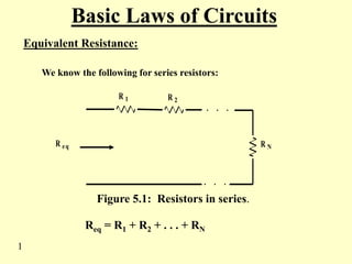
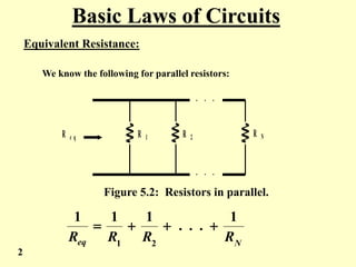
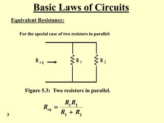
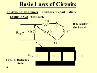
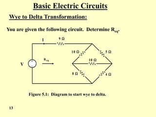
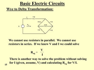
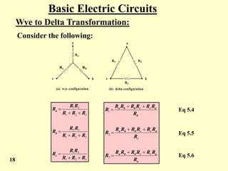
EEE112
Basic Laws of Electric Circuits
Equivalent Resistance UNIT 1
Basic Laws of Circuits
Equivalent Resistance:
We know the following for series resistors:
. . .
. . .
R 1 R 2
R eq R N
Figure 5.1: Resistors in series.
Req = R1 + R2 + . . . + RN
1
Basic Laws of Circuits
Equivalent Resistance:
We know the following for parallel resistors:
. . .
. . .
R e q R 1 R 2 R N
Figure 5.2: Resistors in parallel.
N
eq R
R
R
R
1
.
.
.
1
1
1
2
1




2
Basic Laws of Circuits
Equivalent Resistance:
For the special case of two resistors in parallel:
R e q R 1 R 2
Figure 5.3: Two resistors in parallel.
2
1
2
1
R
R
R
R
Req


3
Basic Laws of Circuits
Equivalent Resistance: Resistors in combination.
By combination we mean we have a mix of series and
Parallel. This is illustrated below.
R 1
R 2
R 3
R 4 R 5
R e q
Figure 5.4: Resistors In Series – Parallel Combination
To find the equivalent resistance we usually start at
the output of the circuit and work back to the input.
4
Basic Laws of Circuits
Equivalent Resistance: Resistors in combination.
R1
R2
R3
Rx
Req
5
4
5
4
R
R
R
R
Rx


R1
R2 Ry
Req 3
R
R
R x
y 

Figure 5.5: Resistance reduction.
5
Basic Laws of Circuits
Equivalent Resistance: Resistors in combination.
R1
RZ
Req
Y
Y
Z R
R
R
R
R


2
2
R
e
q
1
R
R
R Z
eq 

Figure 5.6: Resistance reduction, final steps.
6
Basic Laws of Circuits
Equivalent Resistance: Resistors in combination.
It is easier to work the previous problem using numbers than to
work out a general expression. This is illustrated below.
Example 5.1: Given the circuit below. Find Req.
R eq
6 
3 
8 
10 
10 
Figure 5.7: Circuit for Example 5.1.
7
Basic Laws of Circuits
Equivalent Resistance: Resistors in combination.
Example 5.1: Continued. We start at the right hand side
of the circuit and work to the left.
10 
10 
8 
2 
Req
10 
5 
Req
Figure 5.8: Reduction steps for Example 5.1.

 15
eq
R
Ans:
8
Basic Laws of Circuits
Equivalent Resistance: Resistors in combination.
Example 5.2: Given the circuit shown below. Find Req.
c b a
d
Req
4 
12 
6 
10 
Figure 5.9: Diagram for Example 5.2.
9
Basic Laws of Circuits
Equivalent Resistance: Resistors in combination.
Example 5.2: Continued.
c b
d , a
R e q
4 
1 2 
6  1 0 
c b a
d
Req
4 
12 
6 
10 
Fig 5.10: Reduction
steps.
10
c b
d, a
R eq
4 
12 
6  10 
1 2 
6 
4 
Fig 5.11: Reduction
steps.
Req
10  resistor
shorted out
Basic Laws of Circuits
Equivalent Resistance: Resistors in combination.
Example 5.2: Continued.
11
Basic Laws of Circuits
Equivalent Resistance: Resistors in combination.
Example 5.2: Continued.
4 
4 
1 2 
6 
4 
Fig 5.12: Reduction
steps.
Req
Req
12
Basic Electric Circuits
Wye to Delta Transformation:
You are given the following circuit. Determine Req.
9 
10  5 
8  4 
V
+
_
Req 10 
I
Figure 5.1: Diagram to start wye to delta.
13
Basic Electric Circuits
Wye to Delta Transformation:
You are given the following circuit. Determine Req.
9 
10  5 
8  4 
V
+
_
Req 10 
I
Figure 5.13: Diagram to start wye to delta.
14
Basic Electric Circuits
Wye to Delta Transformation:
9 
10  5 
8  4 
V
+
_
Req 10 
I
We cannot use resistors in parallel. We cannot use
resistors in series. If we knew V and I we could solve
Req =
V
I
There is another way to solve the problem without solving
for I (given, assume, V) and calculating Req for V/I.
15
Basic Electric Circuits
Wye to Delta Transformation:
Consider the following:


   
a
b
c
a
b
c
Ra
Rb
Rc
R1 R2
R3
(a) wye configuration (b) delta configuration
We equate the resistance of Rab, Rac and Rca of (a)
to Rab , Rac and Rca of (b) respectively.
Figure 5.14: Wye to delta circuits.
16
Basic Electric Circuits
Wye to Delta Transformation:
Consider the following:


   
a
b
c
a
b
c
Ra
Rb
Rc
R1 R2
R3
(a) wye configuration (b) delta configuration
Rab = Ra + Rb =
Rac = Ra + Rc =
Rca = Rb + Rc =
R1 + R2 + R3
R1 + R2 + R3
R1 + R2 + R3
R2(R1 + R3)
R1(R2 + R3)
R3(R1 + R2)
Eq 5.1
Eq 5.2
Eq 5.3
17
Basic Electric Circuits
Wye to Delta Transformation:
Consider the following:


   
a
b
c
a
b
c
Ra
Rb
Rc
R1 R2
R3
(a) wye configuration (b) delta configuration
a
a
c
c
b
b
a
c
a
c
c
b
b
a
b
a
c
c
b
b
a
R
R
R
R
R
R
R
R
R
R
R
R
R
R
R
R
R
R
R
R
R
R
R
R









3
2
1
3
2
1
3
1
3
2
1
3
2
3
2
1
2
1
R
R
R
R
R
R
R
R
R
R
R
R
R
R
R
R
R
R
c
b
a








 Eq 5.4
Eq 5.5
Eq 5.6
18
19
a
a
c
c
b
b
a
c
a
c
c
b
b
a
b
a
c
c
b
b
a
R
R
R
R
R
R
R
R
R
R
R
R
R
R
R
R
R
R
R
R
R
R
R
R









3
2
1
3
2
1
3
1
3
2
1
3
2
3
2
1
2
1
R
R
R
R
R
R
R
R
R
R
R
R
R
R
R
R
R
R
c
b
a








 Eq 5.4
Eq 5.5
Eq 5.6
Basic Electric Circuits
Wye to Delta Transformation:
Observe the following:
We note that the denominator for Ra, Rb, Rc is the same.
We note that the numerator for R1, R2, R3 is the same.
We could say “Y” below: “D”
Go to delta
Go to wye
20
Basic Electric Circuits
Wye to Delta Transformation:
Example 5.3: Return to the circuit of Figure 5.13 and find Req.
9 
10  5 
8  4 
V
+
_
Req 10 
I
a
b
c
Convert the delta around a – b – c to a wye.
Basic Electric Circuits
Wye to Delta Transformation:
Example 5.3: continued
2 
2 
4 
4 
8 
9 
Req
21
Figure 5.15: Example 5.3 diagram.
It is easy to see that Req = 15 
22
Basic Electric Circuits
Wye to Delta Transformation:
Example 5.4: Using wye to delta. The circuit of 5.13
may be redrawn as shown in 5.16.
R e q
9 
1 0  5 
8  4 
1 0 
a
b
c
Figure 5.16: “Stretching” (rearranging) the circuit.
Convert the wye of a – b – c to a delta.
Basic Electric Circuits
Wye to Delta Transformation:
Example 5.4: continued
R e q
9 
1 0 
8 
1 1 
2 7 .5 
2 2 
a
b
c R e q
9 
7 .3 3 
5 .8 7 
1 1 
Figure 5.17: Circuit reduction of Example 5.4.
(a) (b)
23
a
b
c
Basic Electric Circuits
Wye to Delta Transformation:
Example 5.4: continued
Req
9 
11 
13.2 
Figure 5.18: Reduction of Figure 5.17.
Req = 15 
This answer checks with the delta to wye solution earlier.
24

UNIT1 Resistance, Equivalent.ppt

  • 1.
    EEE112 Basic Laws ofElectric Circuits Equivalent Resistance UNIT 1
  • 2.
    Basic Laws ofCircuits Equivalent Resistance: We know the following for series resistors: . . . . . . R 1 R 2 R eq R N Figure 5.1: Resistors in series. Req = R1 + R2 + . . . + RN 1
  • 3.
    Basic Laws ofCircuits Equivalent Resistance: We know the following for parallel resistors: . . . . . . R e q R 1 R 2 R N Figure 5.2: Resistors in parallel. N eq R R R R 1 . . . 1 1 1 2 1     2
  • 4.
    Basic Laws ofCircuits Equivalent Resistance: For the special case of two resistors in parallel: R e q R 1 R 2 Figure 5.3: Two resistors in parallel. 2 1 2 1 R R R R Req   3
  • 5.
    Basic Laws ofCircuits Equivalent Resistance: Resistors in combination. By combination we mean we have a mix of series and Parallel. This is illustrated below. R 1 R 2 R 3 R 4 R 5 R e q Figure 5.4: Resistors In Series – Parallel Combination To find the equivalent resistance we usually start at the output of the circuit and work back to the input. 4
  • 6.
    Basic Laws ofCircuits Equivalent Resistance: Resistors in combination. R1 R2 R3 Rx Req 5 4 5 4 R R R R Rx   R1 R2 Ry Req 3 R R R x y   Figure 5.5: Resistance reduction. 5
  • 7.
    Basic Laws ofCircuits Equivalent Resistance: Resistors in combination. R1 RZ Req Y Y Z R R R R R   2 2 R e q 1 R R R Z eq   Figure 5.6: Resistance reduction, final steps. 6
  • 8.
    Basic Laws ofCircuits Equivalent Resistance: Resistors in combination. It is easier to work the previous problem using numbers than to work out a general expression. This is illustrated below. Example 5.1: Given the circuit below. Find Req. R eq 6  3  8  10  10  Figure 5.7: Circuit for Example 5.1. 7
  • 9.
    Basic Laws ofCircuits Equivalent Resistance: Resistors in combination. Example 5.1: Continued. We start at the right hand side of the circuit and work to the left. 10  10  8  2  Req 10  5  Req Figure 5.8: Reduction steps for Example 5.1.   15 eq R Ans: 8
  • 10.
    Basic Laws ofCircuits Equivalent Resistance: Resistors in combination. Example 5.2: Given the circuit shown below. Find Req. c b a d Req 4  12  6  10  Figure 5.9: Diagram for Example 5.2. 9
  • 11.
    Basic Laws ofCircuits Equivalent Resistance: Resistors in combination. Example 5.2: Continued. c b d , a R e q 4  1 2  6  1 0  c b a d Req 4  12  6  10  Fig 5.10: Reduction steps. 10
  • 12.
    c b d, a Req 4  12  6  10  1 2  6  4  Fig 5.11: Reduction steps. Req 10  resistor shorted out Basic Laws of Circuits Equivalent Resistance: Resistors in combination. Example 5.2: Continued. 11
  • 13.
    Basic Laws ofCircuits Equivalent Resistance: Resistors in combination. Example 5.2: Continued. 4  4  1 2  6  4  Fig 5.12: Reduction steps. Req Req 12
  • 14.
    Basic Electric Circuits Wyeto Delta Transformation: You are given the following circuit. Determine Req. 9  10  5  8  4  V + _ Req 10  I Figure 5.1: Diagram to start wye to delta. 13
  • 15.
    Basic Electric Circuits Wyeto Delta Transformation: You are given the following circuit. Determine Req. 9  10  5  8  4  V + _ Req 10  I Figure 5.13: Diagram to start wye to delta. 14
  • 16.
    Basic Electric Circuits Wyeto Delta Transformation: 9  10  5  8  4  V + _ Req 10  I We cannot use resistors in parallel. We cannot use resistors in series. If we knew V and I we could solve Req = V I There is another way to solve the problem without solving for I (given, assume, V) and calculating Req for V/I. 15
  • 17.
    Basic Electric Circuits Wyeto Delta Transformation: Consider the following:       a b c a b c Ra Rb Rc R1 R2 R3 (a) wye configuration (b) delta configuration We equate the resistance of Rab, Rac and Rca of (a) to Rab , Rac and Rca of (b) respectively. Figure 5.14: Wye to delta circuits. 16
  • 18.
    Basic Electric Circuits Wyeto Delta Transformation: Consider the following:       a b c a b c Ra Rb Rc R1 R2 R3 (a) wye configuration (b) delta configuration Rab = Ra + Rb = Rac = Ra + Rc = Rca = Rb + Rc = R1 + R2 + R3 R1 + R2 + R3 R1 + R2 + R3 R2(R1 + R3) R1(R2 + R3) R3(R1 + R2) Eq 5.1 Eq 5.2 Eq 5.3 17
  • 19.
    Basic Electric Circuits Wyeto Delta Transformation: Consider the following:       a b c a b c Ra Rb Rc R1 R2 R3 (a) wye configuration (b) delta configuration a a c c b b a c a c c b b a b a c c b b a R R R R R R R R R R R R R R R R R R R R R R R R          3 2 1 3 2 1 3 1 3 2 1 3 2 3 2 1 2 1 R R R R R R R R R R R R R R R R R R c b a          Eq 5.4 Eq 5.5 Eq 5.6 18
  • 20.
    19 a a c c b b a c a c c b b a b a c c b b a R R R R R R R R R R R R R R R R R R R R R R R R          3 2 1 3 2 1 3 1 3 2 1 3 2 3 2 1 2 1 R R R R R R R R R R R R R R R R R R c b a          Eq 5.4 Eq5.5 Eq 5.6 Basic Electric Circuits Wye to Delta Transformation: Observe the following: We note that the denominator for Ra, Rb, Rc is the same. We note that the numerator for R1, R2, R3 is the same. We could say “Y” below: “D” Go to delta Go to wye
  • 21.
    20 Basic Electric Circuits Wyeto Delta Transformation: Example 5.3: Return to the circuit of Figure 5.13 and find Req. 9  10  5  8  4  V + _ Req 10  I a b c Convert the delta around a – b – c to a wye.
  • 22.
    Basic Electric Circuits Wyeto Delta Transformation: Example 5.3: continued 2  2  4  4  8  9  Req 21 Figure 5.15: Example 5.3 diagram. It is easy to see that Req = 15 
  • 23.
    22 Basic Electric Circuits Wyeto Delta Transformation: Example 5.4: Using wye to delta. The circuit of 5.13 may be redrawn as shown in 5.16. R e q 9  1 0  5  8  4  1 0  a b c Figure 5.16: “Stretching” (rearranging) the circuit. Convert the wye of a – b – c to a delta.
  • 24.
    Basic Electric Circuits Wyeto Delta Transformation: Example 5.4: continued R e q 9  1 0  8  1 1  2 7 .5  2 2  a b c R e q 9  7 .3 3  5 .8 7  1 1  Figure 5.17: Circuit reduction of Example 5.4. (a) (b) 23 a b c
  • 25.
    Basic Electric Circuits Wyeto Delta Transformation: Example 5.4: continued Req 9  11  13.2  Figure 5.18: Reduction of Figure 5.17. Req = 15  This answer checks with the delta to wye solution earlier. 24