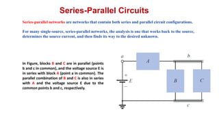
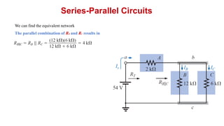
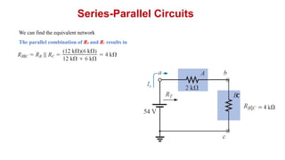
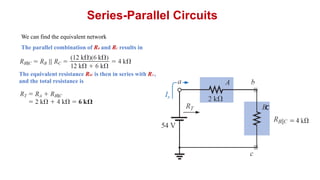
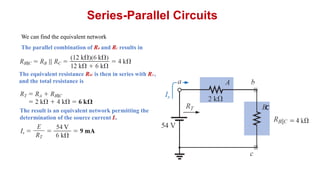
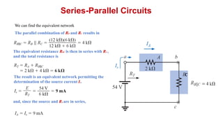
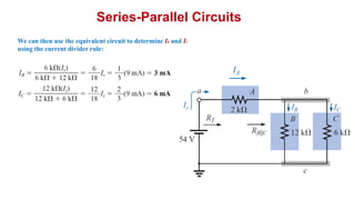
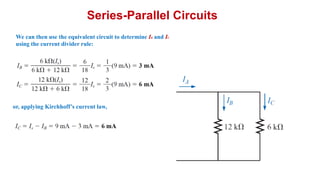
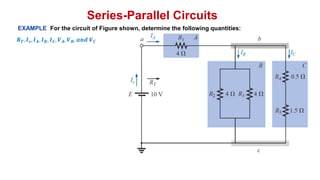
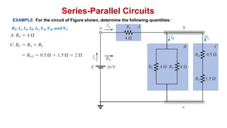
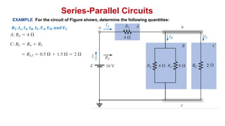
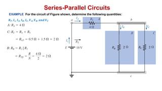
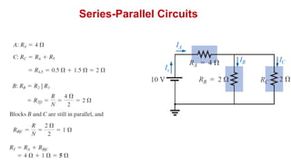
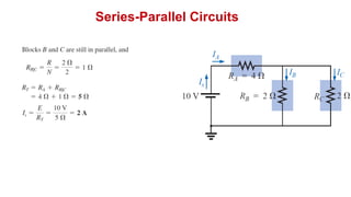
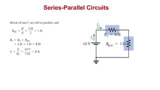
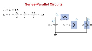
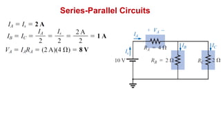
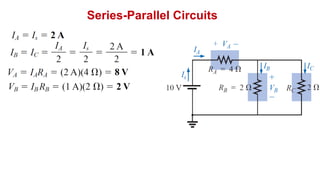
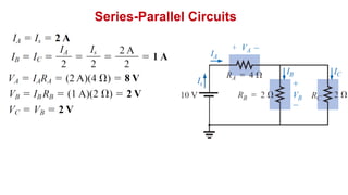
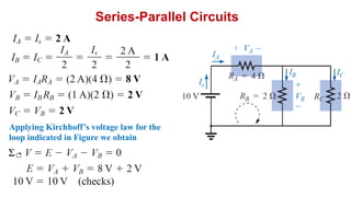
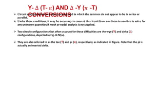
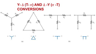
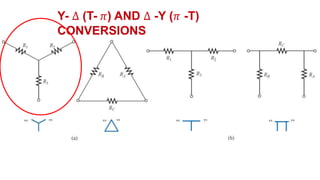
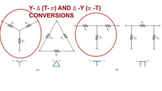
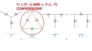
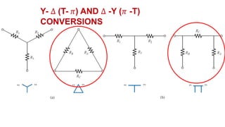
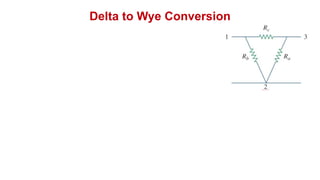
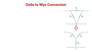
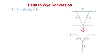
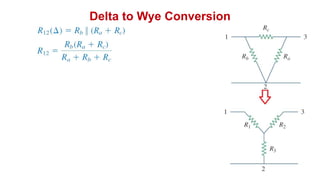
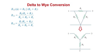
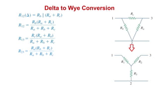
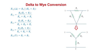
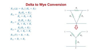
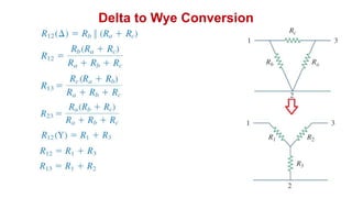
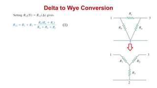
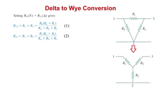
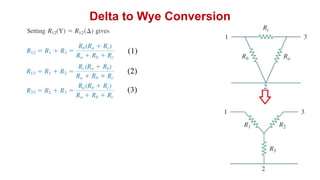
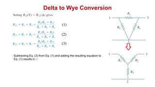
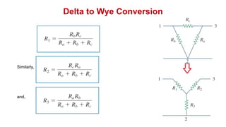
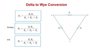
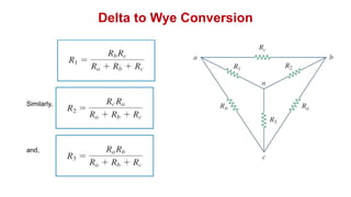
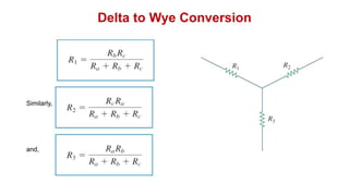
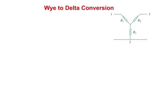
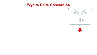
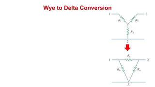
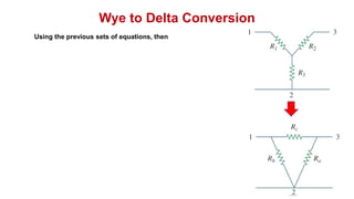
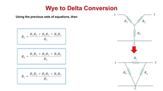
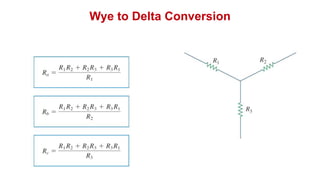
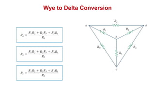
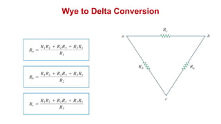
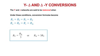
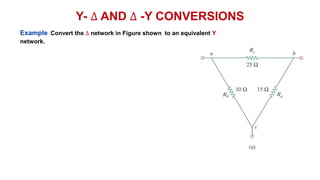
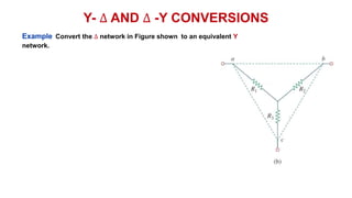
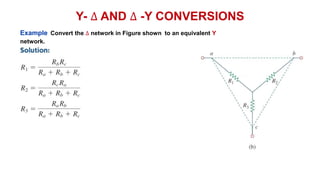
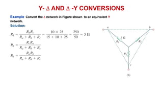
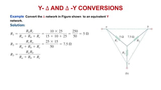
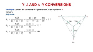
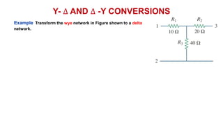
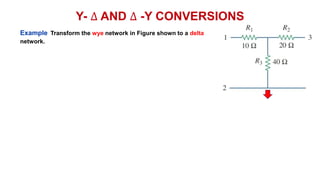
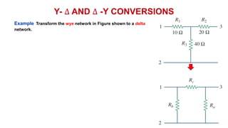
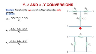
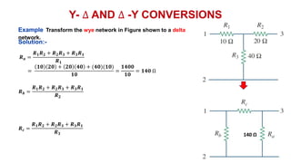
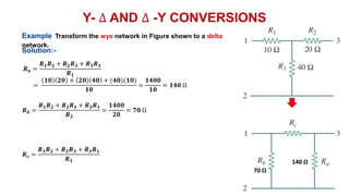
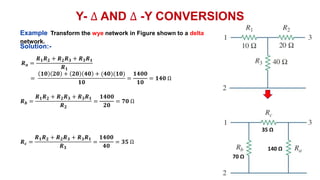
‫د‬
.
‫عبدهللا‬ ‫سليمان‬ ‫احمد‬
By Dr. Ahmed S. Abdullah
Series-Parallel Circuits
DC Circuits
Series-Parallel Circuits
Series-parallel networks are networks that contain both series and parallel circuit configurations.
For many single-source, series-parallel networks, the analysis is one that works back to the source,
determines the source current, and then finds its way to the desired unknown.
In Figure, blocks B and C are in parallel (points
b and c in common), and the voltage source E is
in series with block A (point a in common). The
parallel combination of B and C is also in series
with A and the voltage source E due to the
common points b and c, respectively.
Series-Parallel Circuits
We can find the equivalent network
The parallel combination of RB and RC results in
Series-Parallel Circuits
We can find the equivalent network
The parallel combination of RB and RC results in
C
Series-Parallel Circuits
We can find the equivalent network
The parallel combination of RB and RC results in
The equivalent resistance RBC is then in series with RA ,
and the total resistance is
C
Series-Parallel Circuits
We can find the equivalent network
The parallel combination of RB and RC results in
The result is an equivalent network permitting the
determination of the source current Is.
The equivalent resistance RBC is then in series with RA ,
and the total resistance is
C
Series-Parallel Circuits
We can find the equivalent network
The parallel combination of RB and RC results in
The result is an equivalent network permitting the
determination of the source current Is.
and, since the source and RA are in series,
The equivalent resistance RBC is then in series with RA ,
and the total resistance is
C
Series-Parallel Circuits
We can then use the equivalent circuit to determine IB and IC
using the current divider rule:
Series-Parallel Circuits
We can then use the equivalent circuit to determine IB and IC
using the current divider rule:
or, applying Kirchhoff’s current law,
Series-Parallel Circuits
EXAMPLE For the circuit of Figure shown, determine the following quantities:
𝑹𝑻, 𝑰𝒔, 𝑰𝑨, 𝑰𝑩, 𝑰𝑪, 𝑽𝑨, 𝑽𝑩, 𝒂𝒏𝒅 𝑽𝑪
Series-Parallel Circuits
EXAMPLE For the circuit of Figure shown, determine the following quantities:
𝑹𝑻, 𝑰𝒔, 𝑰𝑨, 𝑰𝑩, 𝑰𝑪, 𝑽𝑨, 𝑽𝑩, 𝒂𝒏𝒅 𝑽𝑪
Series-Parallel Circuits
EXAMPLE For the circuit of Figure shown, determine the following quantities:
𝑹𝑻, 𝑰𝒔, 𝑰𝑨, 𝑰𝑩, 𝑰𝑪, 𝑽𝑨, 𝑽𝑩, 𝒂𝒏𝒅 𝑽𝑪
Series-Parallel Circuits
EXAMPLE For the circuit of Figure shown, determine the following quantities:
𝑹𝑻, 𝑰𝒔, 𝑰𝑨, 𝑰𝑩, 𝑰𝑪, 𝑽𝑨, 𝑽𝑩, 𝒂𝒏𝒅 𝑽𝑪
Series-Parallel Circuits
EXAMPLE For the circuit of Figure shown, determine the following quantities:
𝑹𝑻, 𝑰𝒔, 𝑰𝑨, 𝑰𝑩, 𝑰𝑪, 𝑽𝑨, 𝑽𝑩, 𝒂𝒏𝒅 𝑽𝑪
Series-Parallel Circuits
Applying Kirchhoff’s voltage law for the
loop indicated in Figure we obtain
Y- ∆ (T- 𝜋) AND ∆ -Y (𝜋 -T)
CONVERSIONS
 Circuit configurations are often encountered in which the resistors do not appear to be in series or
parallel.
 Under these conditions, it may be necessary to convert the circuit from one form to another to solve for
any unknown quantities if mesh or nodal analysis is not applied.
 Two circuit configurations that often account for these difficulties are the wye (Y) and delta (∆)
configurations, depicted in Fig. 8.72(a).
 They are also referred to as the tee (T) and pi (𝛑), respectively, as indicated in Figure. Note that the pi is
actually an inverted delta.
Y- ∆ (T- 𝜋) AND ∆ -Y (𝜋 -T)
CONVERSIONS
Y- ∆ (T- 𝜋) AND ∆ -Y (𝜋 -T)
CONVERSIONS
Y- ∆ (T- 𝜋) AND ∆ -Y (𝜋 -T)
CONVERSIONS
Y- ∆ (T- 𝜋) AND ∆ -Y (𝜋 -T)
CONVERSIONS
Y- ∆ (T- 𝜋) AND ∆ -Y (𝜋 -T)
CONVERSIONS
Delta to Wye Conversion
Subtracting Eq. (3) from Eq. (1) and adding the resulting equation to
Eq. (1) results in :-
Delta to Wye Conversion
Similarly,
and,
Delta to Wye Conversion
Similarly,
and,
Delta to Wye Conversion
Similarly,
and,
Delta to Wye Conversion
Similarly,
and,
Wye to Delta Conversion
Using the previous sets of equations, then
Wye to Delta Conversion
Using the previous sets of equations, then
Wye to Delta Conversion
Y- ∆ AND ∆ -Y CONVERSIONS
The Y and ∆ networks are said to be balanced when
Y- ∆ AND ∆ -Y CONVERSIONS
The Y and ∆ networks are said to be balanced when
Y- ∆ AND ∆ -Y CONVERSIONS
The Y and ∆ networks are said to be balanced when
Y- ∆ AND ∆ -Y CONVERSIONS
The Y and ∆ networks are said to be balanced when
Y- ∆ AND ∆ -Y CONVERSIONS
The Y and ∆ networks are said to be balanced when
Y- ∆ AND ∆ -Y CONVERSIONS
The Y and ∆ networks are said to be balanced when
Under these conditions, conversion formulas become
Y- ∆ AND ∆ -Y CONVERSIONS
Example Convert the ∆ network in Figure shown to an equivalent Y
network.
Y- ∆ AND ∆ -Y CONVERSIONS
Example Convert the ∆ network in Figure shown to an equivalent Y
network.
Y- ∆ AND ∆ -Y CONVERSIONS
Example Convert the ∆ network in Figure shown to an equivalent Y
network.
Y- ∆ AND ∆ -Y CONVERSIONS
Example Convert the ∆ network in Figure shown to an equivalent Y
network.
Y- ∆ AND ∆ -Y CONVERSIONS
Example Convert the ∆ network in Figure shown to an equivalent Y
network.
Y- ∆ AND ∆ -Y CONVERSIONS
Example Convert the ∆ network in Figure shown to an equivalent Y
network.
Y- ∆ AND ∆ -Y CONVERSIONS
Example Transform the wye network in Figure shown to a delta
network.
Y- ∆ AND ∆ -Y CONVERSIONS
Example Transform the wye network in Figure shown to a delta
network.
Y- ∆ AND ∆ -Y CONVERSIONS
Example Transform the wye network in Figure shown to a delta
network.
Y- ∆ AND ∆ -Y CONVERSIONS
Example Transform the wye network in Figure shown to a delta
network.
𝑹𝒂 =
𝑹𝟏𝑹𝟐 + 𝑹𝟐𝑹𝟑 + 𝑹𝟑𝑹𝟏
𝑹𝟏
𝑹𝒃 =
𝑹𝟏𝑹𝟐 + 𝑹𝟐𝑹𝟑 + 𝑹𝟑𝑹𝟏
𝑹𝟐
𝑹𝒄 =
𝑹𝟏𝑹𝟐 + 𝑹𝟐𝑹𝟑 + 𝑹𝟑𝑹𝟏
𝑹𝟑
Solution:-
Y- ∆ AND ∆ -Y CONVERSIONS
Example Transform the wye network in Figure shown to a delta
network.
𝑹𝒂 =
𝑹𝟏𝑹𝟐 + 𝑹𝟐𝑹𝟑 + 𝑹𝟑𝑹𝟏
𝑹𝟏
=
𝟏𝟎 𝟐𝟎 + 𝟐𝟎 𝟒𝟎 + (𝟒𝟎)(𝟏𝟎)
𝟏𝟎
=
𝟏𝟒𝟎𝟎
𝟏𝟎
= 𝟏𝟒𝟎 Ω
𝑹𝒃 =
𝑹𝟏𝑹𝟐 + 𝑹𝟐𝑹𝟑 + 𝑹𝟑𝑹𝟏
𝑹𝟐
𝑹𝒄 =
𝑹𝟏𝑹𝟐 + 𝑹𝟐𝑹𝟑 + 𝑹𝟑𝑹𝟏
𝑹𝟑
Solution:-
140 Ω
Y- ∆ AND ∆ -Y CONVERSIONS
Example Transform the wye network in Figure shown to a delta
network.
𝑹𝒂 =
𝑹𝟏𝑹𝟐 + 𝑹𝟐𝑹𝟑 + 𝑹𝟑𝑹𝟏
𝑹𝟏
=
𝟏𝟎 𝟐𝟎 + 𝟐𝟎 𝟒𝟎 + (𝟒𝟎)(𝟏𝟎)
𝟏𝟎
=
𝟏𝟒𝟎𝟎
𝟏𝟎
= 𝟏𝟒𝟎 Ω
𝑹𝒃 =
𝑹𝟏𝑹𝟐 + 𝑹𝟐𝑹𝟑 + 𝑹𝟑𝑹𝟏
𝑹𝟐
=
𝟏𝟒𝟎𝟎
𝟐𝟎
= 𝟕𝟎 Ω
𝑹𝒄 =
𝑹𝟏𝑹𝟐 + 𝑹𝟐𝑹𝟑 + 𝑹𝟑𝑹𝟏
𝑹𝟑
Solution:-
140 Ω
70 Ω
Y- ∆ AND ∆ -Y CONVERSIONS
Example Transform the wye network in Figure shown to a delta
network.
𝑹𝒂 =
𝑹𝟏𝑹𝟐 + 𝑹𝟐𝑹𝟑 + 𝑹𝟑𝑹𝟏
𝑹𝟏
=
𝟏𝟎 𝟐𝟎 + 𝟐𝟎 𝟒𝟎 + (𝟒𝟎)(𝟏𝟎)
𝟏𝟎
=
𝟏𝟒𝟎𝟎
𝟏𝟎
= 𝟏𝟒𝟎 Ω
𝑹𝒃 =
𝑹𝟏𝑹𝟐 + 𝑹𝟐𝑹𝟑 + 𝑹𝟑𝑹𝟏
𝑹𝟐
=
𝟏𝟒𝟎𝟎
𝟐𝟎
= 𝟕𝟎 Ω
𝑹𝒄 =
𝑹𝟏𝑹𝟐 + 𝑹𝟐𝑹𝟑 + 𝑹𝟑𝑹𝟏
𝑹𝟑
=
𝟏𝟒𝟎𝟎
𝟒𝟎
= 𝟑𝟓 Ω
Solution:-
140 Ω
70 Ω
35 Ω
References
 Boylestad, Robert L. Introductory circuit analysis. Pearson Education, 2010.
 Robbins, Allan H., and Wilhelm C. Miller. Circuit analysis: Theory and
practice. Cengage Learning, 2012.
 Sadiku, Matthew NO, and Chales K. Alexander. Fundamentals of electric
circuits. McGraw-Hill Higher Education, 2007.

Series-Parallel Circuits for electrical circuit.pptx

  • 1.
    ‫د‬ . ‫عبدهللا‬ ‫سليمان‬ ‫احمد‬ ByDr. Ahmed S. Abdullah Series-Parallel Circuits DC Circuits
  • 2.
    Series-Parallel Circuits Series-parallel networksare networks that contain both series and parallel circuit configurations. For many single-source, series-parallel networks, the analysis is one that works back to the source, determines the source current, and then finds its way to the desired unknown. In Figure, blocks B and C are in parallel (points b and c in common), and the voltage source E is in series with block A (point a in common). The parallel combination of B and C is also in series with A and the voltage source E due to the common points b and c, respectively.
  • 3.
    Series-Parallel Circuits We canfind the equivalent network The parallel combination of RB and RC results in
  • 4.
    Series-Parallel Circuits We canfind the equivalent network The parallel combination of RB and RC results in C
  • 5.
    Series-Parallel Circuits We canfind the equivalent network The parallel combination of RB and RC results in The equivalent resistance RBC is then in series with RA , and the total resistance is C
  • 6.
    Series-Parallel Circuits We canfind the equivalent network The parallel combination of RB and RC results in The result is an equivalent network permitting the determination of the source current Is. The equivalent resistance RBC is then in series with RA , and the total resistance is C
  • 7.
    Series-Parallel Circuits We canfind the equivalent network The parallel combination of RB and RC results in The result is an equivalent network permitting the determination of the source current Is. and, since the source and RA are in series, The equivalent resistance RBC is then in series with RA , and the total resistance is C
  • 8.
    Series-Parallel Circuits We canthen use the equivalent circuit to determine IB and IC using the current divider rule:
  • 9.
    Series-Parallel Circuits We canthen use the equivalent circuit to determine IB and IC using the current divider rule: or, applying Kirchhoff’s current law,
  • 10.
    Series-Parallel Circuits EXAMPLE Forthe circuit of Figure shown, determine the following quantities: 𝑹𝑻, 𝑰𝒔, 𝑰𝑨, 𝑰𝑩, 𝑰𝑪, 𝑽𝑨, 𝑽𝑩, 𝒂𝒏𝒅 𝑽𝑪
  • 11.
    Series-Parallel Circuits EXAMPLE Forthe circuit of Figure shown, determine the following quantities: 𝑹𝑻, 𝑰𝒔, 𝑰𝑨, 𝑰𝑩, 𝑰𝑪, 𝑽𝑨, 𝑽𝑩, 𝒂𝒏𝒅 𝑽𝑪
  • 12.
    Series-Parallel Circuits EXAMPLE Forthe circuit of Figure shown, determine the following quantities: 𝑹𝑻, 𝑰𝒔, 𝑰𝑨, 𝑰𝑩, 𝑰𝑪, 𝑽𝑨, 𝑽𝑩, 𝒂𝒏𝒅 𝑽𝑪
  • 13.
    Series-Parallel Circuits EXAMPLE Forthe circuit of Figure shown, determine the following quantities: 𝑹𝑻, 𝑰𝒔, 𝑰𝑨, 𝑰𝑩, 𝑰𝑪, 𝑽𝑨, 𝑽𝑩, 𝒂𝒏𝒅 𝑽𝑪
  • 14.
    Series-Parallel Circuits EXAMPLE Forthe circuit of Figure shown, determine the following quantities: 𝑹𝑻, 𝑰𝒔, 𝑰𝑨, 𝑰𝑩, 𝑰𝑪, 𝑽𝑨, 𝑽𝑩, 𝒂𝒏𝒅 𝑽𝑪
  • 15.
  • 16.
  • 17.
  • 18.
  • 19.
  • 20.
  • 21.
  • 22.
    Series-Parallel Circuits Applying Kirchhoff’svoltage law for the loop indicated in Figure we obtain
  • 23.
    Y- ∆ (T-𝜋) AND ∆ -Y (𝜋 -T) CONVERSIONS  Circuit configurations are often encountered in which the resistors do not appear to be in series or parallel.  Under these conditions, it may be necessary to convert the circuit from one form to another to solve for any unknown quantities if mesh or nodal analysis is not applied.  Two circuit configurations that often account for these difficulties are the wye (Y) and delta (∆) configurations, depicted in Fig. 8.72(a).  They are also referred to as the tee (T) and pi (𝛑), respectively, as indicated in Figure. Note that the pi is actually an inverted delta.
  • 24.
    Y- ∆ (T-𝜋) AND ∆ -Y (𝜋 -T) CONVERSIONS
  • 25.
    Y- ∆ (T-𝜋) AND ∆ -Y (𝜋 -T) CONVERSIONS
  • 26.
    Y- ∆ (T-𝜋) AND ∆ -Y (𝜋 -T) CONVERSIONS
  • 27.
    Y- ∆ (T-𝜋) AND ∆ -Y (𝜋 -T) CONVERSIONS
  • 28.
    Y- ∆ (T-𝜋) AND ∆ -Y (𝜋 -T) CONVERSIONS
  • 29.
    Delta to WyeConversion
  • 30.
    Delta to WyeConversion
  • 31.
    Delta to WyeConversion
  • 32.
    Delta to WyeConversion
  • 33.
    Delta to WyeConversion
  • 34.
    Delta to WyeConversion
  • 35.
    Delta to WyeConversion
  • 36.
    Delta to WyeConversion
  • 37.
    Delta to WyeConversion
  • 38.
    Delta to WyeConversion
  • 39.
    Delta to WyeConversion
  • 40.
    Delta to WyeConversion
  • 41.
    Delta to WyeConversion
  • 42.
    Delta to WyeConversion Subtracting Eq. (3) from Eq. (1) and adding the resulting equation to Eq. (1) results in :-
  • 43.
    Delta to WyeConversion Similarly, and,
  • 44.
    Delta to WyeConversion Similarly, and,
  • 45.
    Delta to WyeConversion Similarly, and,
  • 46.
    Delta to WyeConversion Similarly, and,
  • 47.
    Wye to DeltaConversion
  • 48.
    Wye to DeltaConversion
  • 49.
    Wye to DeltaConversion
  • 50.
    Wye to DeltaConversion
  • 51.
    Wye to DeltaConversion Using the previous sets of equations, then
  • 52.
    Wye to DeltaConversion Using the previous sets of equations, then
  • 53.
    Wye to DeltaConversion
  • 54.
    Wye to DeltaConversion
  • 55.
    Wye to DeltaConversion
  • 56.
    Y- ∆ AND∆ -Y CONVERSIONS The Y and ∆ networks are said to be balanced when
  • 57.
    Y- ∆ AND∆ -Y CONVERSIONS The Y and ∆ networks are said to be balanced when
  • 58.
    Y- ∆ AND∆ -Y CONVERSIONS The Y and ∆ networks are said to be balanced when
  • 59.
    Y- ∆ AND∆ -Y CONVERSIONS The Y and ∆ networks are said to be balanced when
  • 60.
    Y- ∆ AND∆ -Y CONVERSIONS The Y and ∆ networks are said to be balanced when
  • 61.
    Y- ∆ AND∆ -Y CONVERSIONS The Y and ∆ networks are said to be balanced when Under these conditions, conversion formulas become
  • 62.
    Y- ∆ AND∆ -Y CONVERSIONS Example Convert the ∆ network in Figure shown to an equivalent Y network.
  • 63.
    Y- ∆ AND∆ -Y CONVERSIONS Example Convert the ∆ network in Figure shown to an equivalent Y network.
  • 64.
    Y- ∆ AND∆ -Y CONVERSIONS Example Convert the ∆ network in Figure shown to an equivalent Y network.
  • 65.
    Y- ∆ AND∆ -Y CONVERSIONS Example Convert the ∆ network in Figure shown to an equivalent Y network.
  • 66.
    Y- ∆ AND∆ -Y CONVERSIONS Example Convert the ∆ network in Figure shown to an equivalent Y network.
  • 67.
    Y- ∆ AND∆ -Y CONVERSIONS Example Convert the ∆ network in Figure shown to an equivalent Y network.
  • 68.
    Y- ∆ AND∆ -Y CONVERSIONS Example Transform the wye network in Figure shown to a delta network.
  • 69.
    Y- ∆ AND∆ -Y CONVERSIONS Example Transform the wye network in Figure shown to a delta network.
  • 70.
    Y- ∆ AND∆ -Y CONVERSIONS Example Transform the wye network in Figure shown to a delta network.
  • 71.
    Y- ∆ AND∆ -Y CONVERSIONS Example Transform the wye network in Figure shown to a delta network. 𝑹𝒂 = 𝑹𝟏𝑹𝟐 + 𝑹𝟐𝑹𝟑 + 𝑹𝟑𝑹𝟏 𝑹𝟏 𝑹𝒃 = 𝑹𝟏𝑹𝟐 + 𝑹𝟐𝑹𝟑 + 𝑹𝟑𝑹𝟏 𝑹𝟐 𝑹𝒄 = 𝑹𝟏𝑹𝟐 + 𝑹𝟐𝑹𝟑 + 𝑹𝟑𝑹𝟏 𝑹𝟑 Solution:-
  • 72.
    Y- ∆ AND∆ -Y CONVERSIONS Example Transform the wye network in Figure shown to a delta network. 𝑹𝒂 = 𝑹𝟏𝑹𝟐 + 𝑹𝟐𝑹𝟑 + 𝑹𝟑𝑹𝟏 𝑹𝟏 = 𝟏𝟎 𝟐𝟎 + 𝟐𝟎 𝟒𝟎 + (𝟒𝟎)(𝟏𝟎) 𝟏𝟎 = 𝟏𝟒𝟎𝟎 𝟏𝟎 = 𝟏𝟒𝟎 Ω 𝑹𝒃 = 𝑹𝟏𝑹𝟐 + 𝑹𝟐𝑹𝟑 + 𝑹𝟑𝑹𝟏 𝑹𝟐 𝑹𝒄 = 𝑹𝟏𝑹𝟐 + 𝑹𝟐𝑹𝟑 + 𝑹𝟑𝑹𝟏 𝑹𝟑 Solution:- 140 Ω
  • 73.
    Y- ∆ AND∆ -Y CONVERSIONS Example Transform the wye network in Figure shown to a delta network. 𝑹𝒂 = 𝑹𝟏𝑹𝟐 + 𝑹𝟐𝑹𝟑 + 𝑹𝟑𝑹𝟏 𝑹𝟏 = 𝟏𝟎 𝟐𝟎 + 𝟐𝟎 𝟒𝟎 + (𝟒𝟎)(𝟏𝟎) 𝟏𝟎 = 𝟏𝟒𝟎𝟎 𝟏𝟎 = 𝟏𝟒𝟎 Ω 𝑹𝒃 = 𝑹𝟏𝑹𝟐 + 𝑹𝟐𝑹𝟑 + 𝑹𝟑𝑹𝟏 𝑹𝟐 = 𝟏𝟒𝟎𝟎 𝟐𝟎 = 𝟕𝟎 Ω 𝑹𝒄 = 𝑹𝟏𝑹𝟐 + 𝑹𝟐𝑹𝟑 + 𝑹𝟑𝑹𝟏 𝑹𝟑 Solution:- 140 Ω 70 Ω
  • 74.
    Y- ∆ AND∆ -Y CONVERSIONS Example Transform the wye network in Figure shown to a delta network. 𝑹𝒂 = 𝑹𝟏𝑹𝟐 + 𝑹𝟐𝑹𝟑 + 𝑹𝟑𝑹𝟏 𝑹𝟏 = 𝟏𝟎 𝟐𝟎 + 𝟐𝟎 𝟒𝟎 + (𝟒𝟎)(𝟏𝟎) 𝟏𝟎 = 𝟏𝟒𝟎𝟎 𝟏𝟎 = 𝟏𝟒𝟎 Ω 𝑹𝒃 = 𝑹𝟏𝑹𝟐 + 𝑹𝟐𝑹𝟑 + 𝑹𝟑𝑹𝟏 𝑹𝟐 = 𝟏𝟒𝟎𝟎 𝟐𝟎 = 𝟕𝟎 Ω 𝑹𝒄 = 𝑹𝟏𝑹𝟐 + 𝑹𝟐𝑹𝟑 + 𝑹𝟑𝑹𝟏 𝑹𝟑 = 𝟏𝟒𝟎𝟎 𝟒𝟎 = 𝟑𝟓 Ω Solution:- 140 Ω 70 Ω 35 Ω
  • 75.
    References  Boylestad, RobertL. Introductory circuit analysis. Pearson Education, 2010.  Robbins, Allan H., and Wilhelm C. Miller. Circuit analysis: Theory and practice. Cengage Learning, 2012.  Sadiku, Matthew NO, and Chales K. Alexander. Fundamentals of electric circuits. McGraw-Hill Higher Education, 2007.