Downloaded 13 times

![International Journal of Electrical Engineering and Technology (IJEET), ISSN 0976 – 6545(Print),
ISSN 0976 – 6553(Online) Volume 6, Issue 5, May (2015), pp. 21-29 © IAEME
24
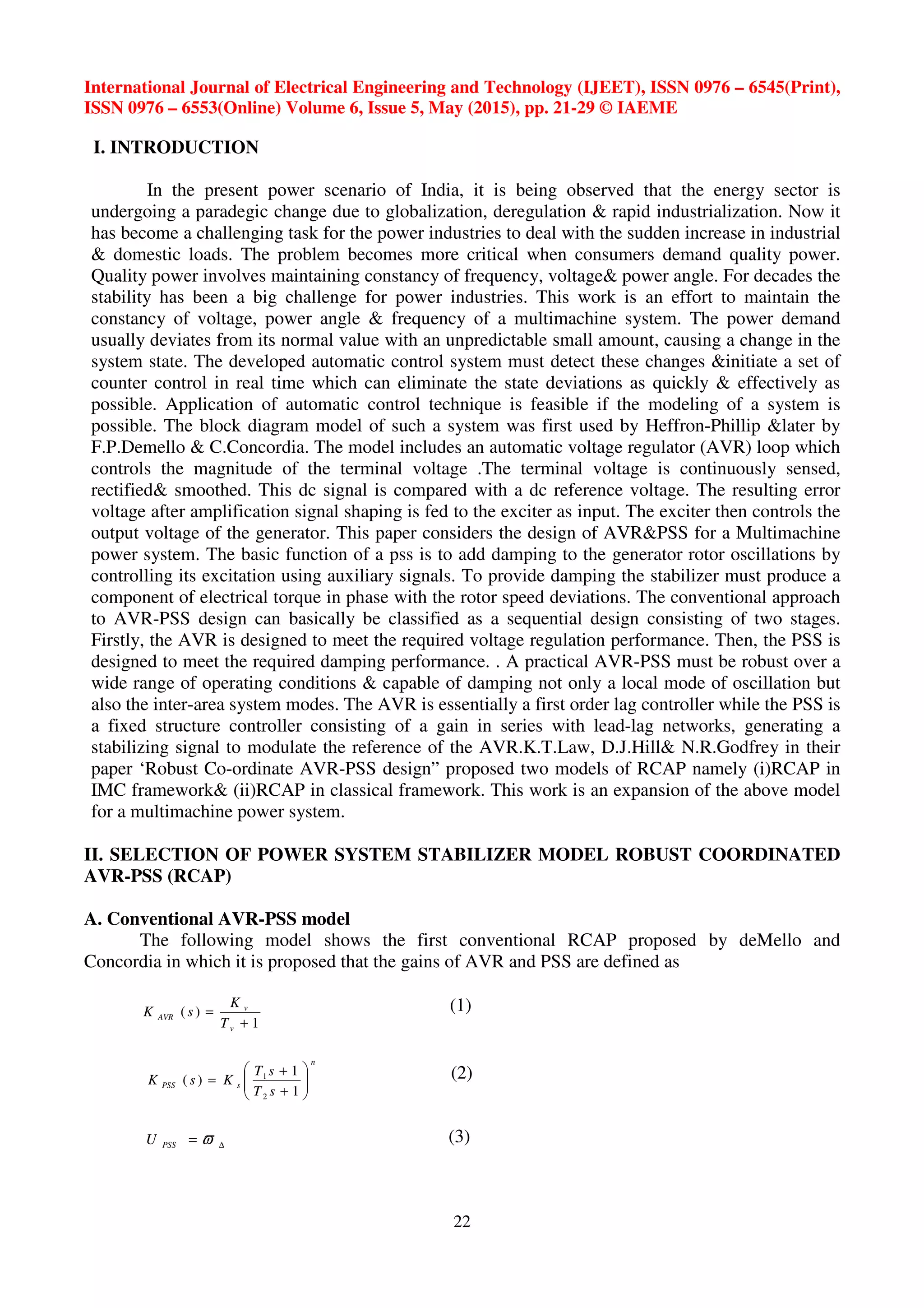
C. RCAP in classical frame work
Fig. 3: RCAP model in classical frame
The modified model of RCAP in IMC framework is known as RCAP in classical frame work.
It consists of two integrating controllers known as C1 and C2 .Here the anti-windup reset scheme is
used to prevent integral windup. In this model the inner field controller,C1 is a standard PI-controller
and C2 has an integrator to ensure zero steady state error. The transfer functions of C1 and C2 are as
follows
The PSS for the inner loop is given by
R
R
PSS
DsD
C
ϖ
ϖ δω +
=
(7)
sK
sM
C
fad
do
λ
τ 1'3
1
+
=
(8)
−++++
++
++
=
6
52
1
2
6
2
1
22
2
)(2)1(
2
M
MM
MsDDHssM
D
K
M
MsD
K
M
DHsK
C
RAVRv
ad
R
ad
ad
ϖλ
ϖ δω
(9)
D. RCAP in classical frame work applied to Multimachine System:
Here, a study has been conducted on a Multimachine system using the above model described
in Fig. 4.4. Two machines of equal per unit rating and equal rated turbines connected through a tie-
line has been selected for this purpose. The details of the parameters are described in table [ ]
Fig 4: Block Diagram of Multimachine System
Fig 5: Load Frequency Model of both machines connected Through Tie-line](https://image.slidesharecdn.com/stabilitystudyofamultimachinesystemusingmodifiedrobustcoordinateavrandpowersystemstabilizer-150820093909-lva1-app6891/75/Stability-study-of-a-multi-machine-system-using-modified-robust-co-ordinate-avr-and-power-system-stabilizer-4-2048.jpg)
![International Journal of Electrical Engineering and Technology (IJEET), ISSN 0976 – 6545(Print),
ISSN 0976 – 6553(Online) Volume 6, Issue 5, May (2015), pp. 21-29 © IAEME
25
Fig 6: Model for Study of change in rotor angle using the new PSS
Fig 7: Model for Study of change in terminal voltage using the new PSS
III. CASE STUDIES
Case-I: A single machine connected to infinite bus system with the proposed PSS model has been
prepared. This model is described in fig. 4.4. The Generator data is mentioned in Table [5.1]. The
model is simulated in the MATLAB platform.
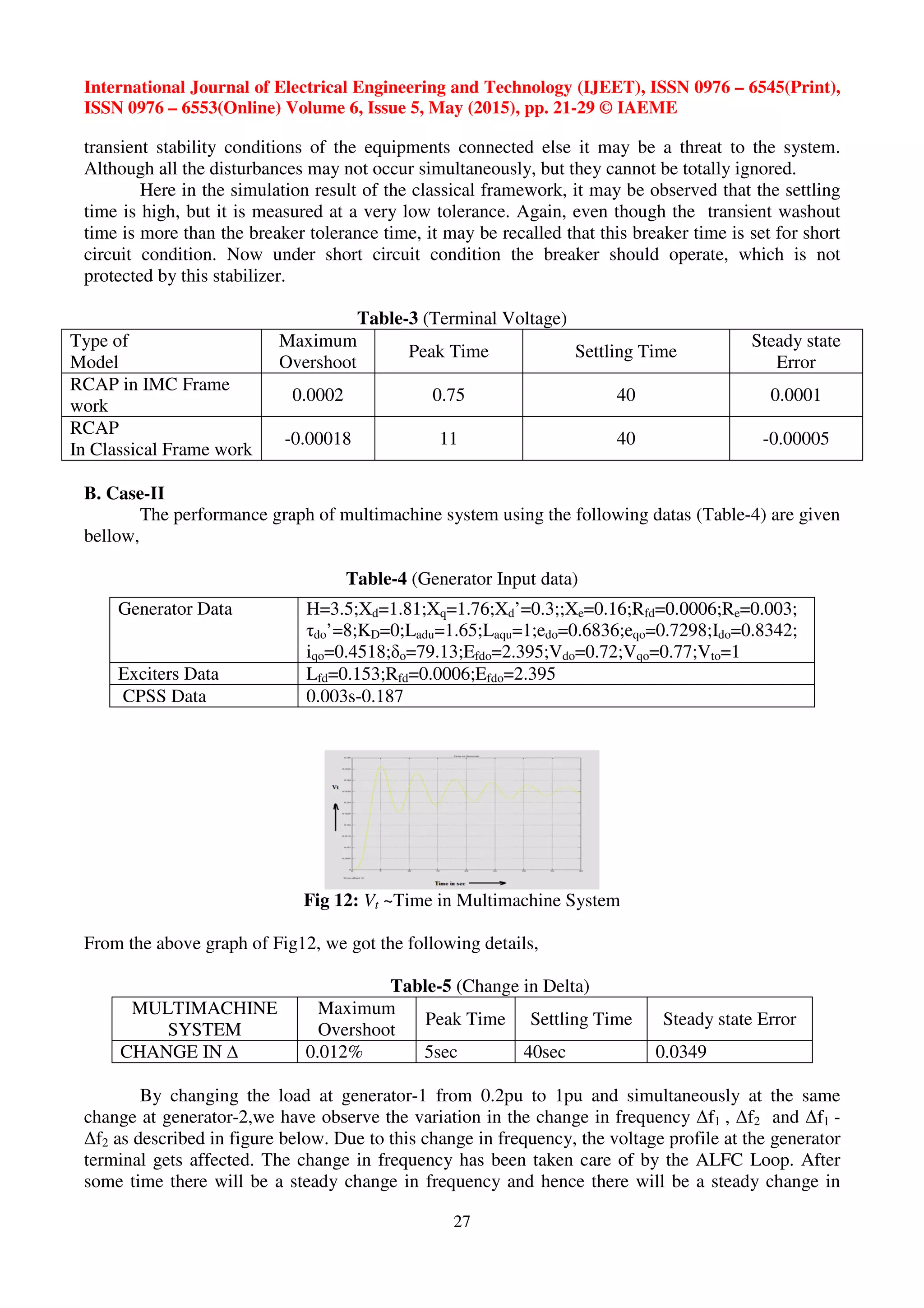
Case-II: A study has been conducted on a Multimachine system using the above model described in
Fig. 4.4. Two machines of equal per unit rating and equal rated turbines connected through a tie-line
has been selected for this purpose. The details of the parameters are described in table.
RESULTS AND DISCUSSION
A: Case-I:
The performances of CPSS are compared between model of RCAP in IMC frame work and
with model in Classical frame work. The system data are summarized below.
Table-1 (Generator Input data)
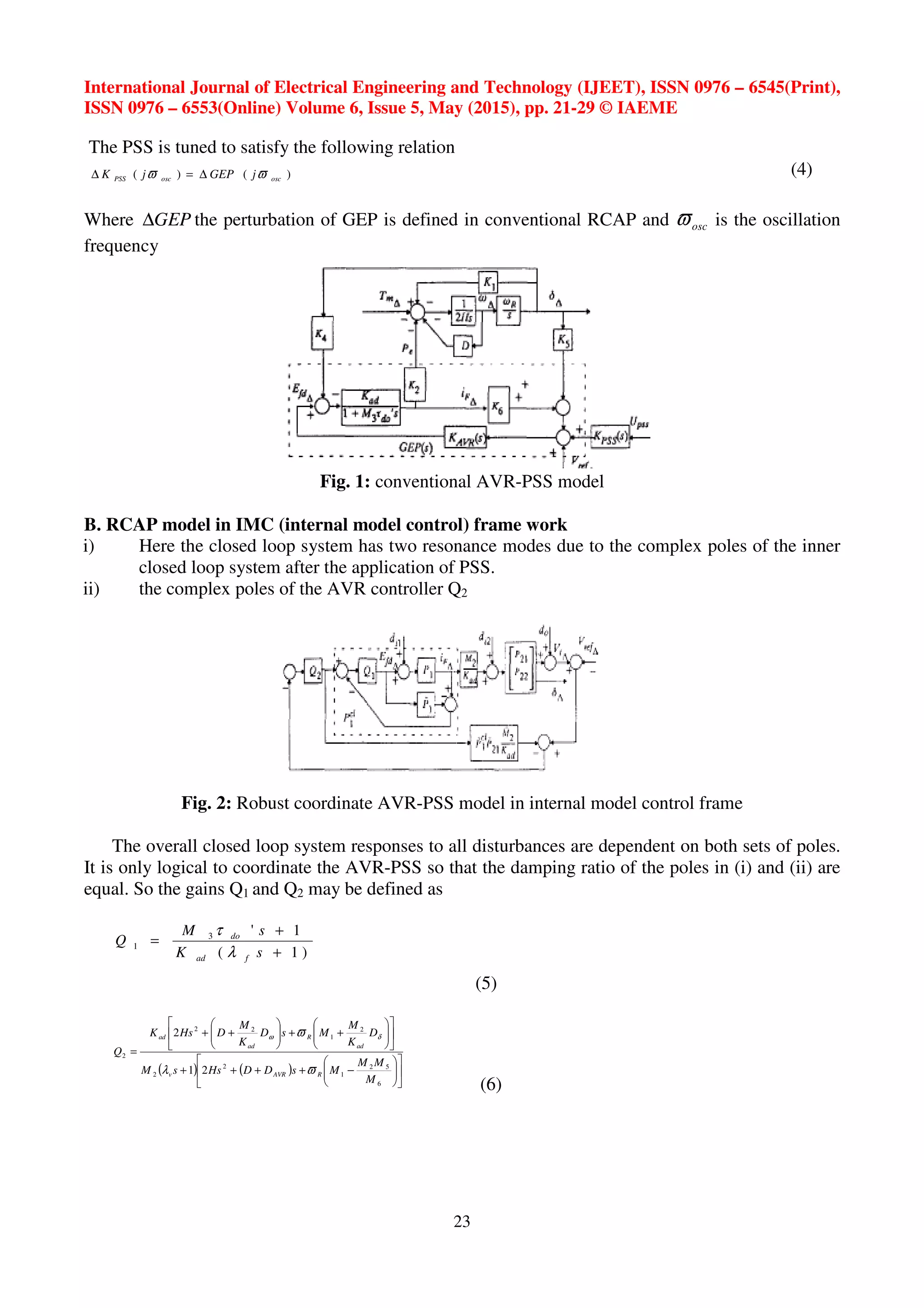
From Table-5.2 it is observed that the peak time for power angle in case of IMC frame work
is faster than that of classical model. As power angle is responsible for power transfer, an oscillatory
response of the same destabilizes the system and questions on the quality power in case of the model
in IMC framework (dominating complex poles are located exactly on
Generator Data H=3.5;Xd=1.81;Xq=1.76;Xd’=0.3;;Xe=0.16;Rfd=0.0006;Re=0.003;
τdo’=8;KD=0;Ladu=1.65;Laqu=1;edo=0.6836;eqo=0.7298;Ido=0.8342;
iqo=0.4518;δo=79.13;Efdo=2.395;Vdo=0.72;Vqo=0.77;Vto=1
Exciters Data Lfd=0.153;Rfd=0.0006;Efdo=2.395
CPSS Data 0.003s-0.187](https://image.slidesharecdn.com/stabilitystudyofamultimachinesystemusingmodifiedrobustcoordinateavrandpowersystemstabilizer-150820093909-lva1-app6891/75/Stability-study-of-a-multi-machine-system-using-modified-robust-co-ordinate-avr-and-power-system-stabilizer-5-2048.jpg)

This document summarizes a study on stability of a multi-machine power system using a modified robust coordinated automatic voltage regulator (AVR) and power system stabilizer (PSS). The study models a multi-machine system using a robust coordinated AVR-PSS (RCAP) control scheme in both an internal model control (IMC) framework and a classical framework. Simulation results show that the classical RCAP framework provides better damping performance than the IMC framework in terms of settling time and overshoot for rotor angle and terminal voltage deviations following disturbances. The study is then expanded to analyze stability of a two-machine power system connected by a tie-line using the classical RCAP model.