Download to read offline
![
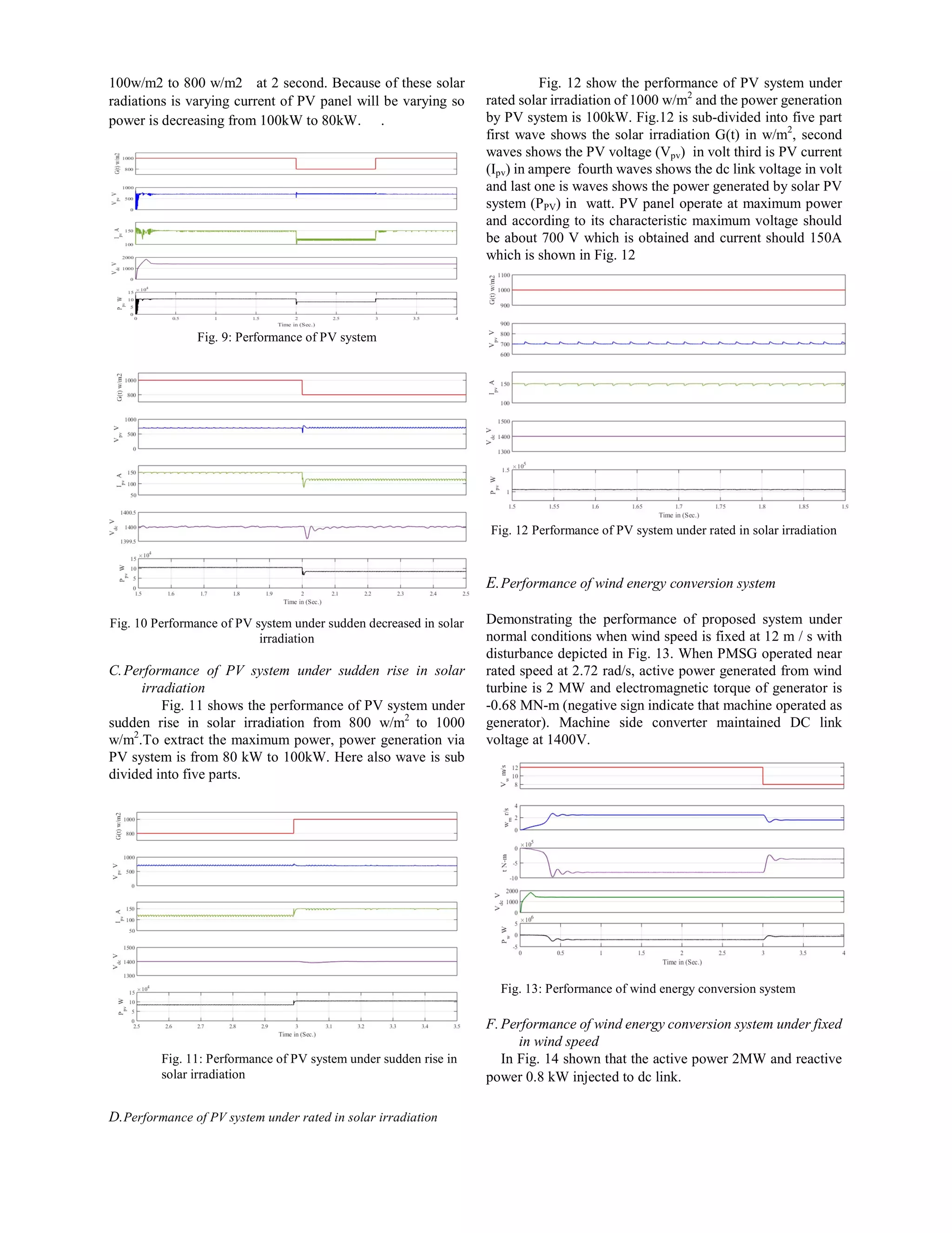
Abstract—In the modern era, grid connected sustainable
energy based hybrid power system is considered as an
alternative source for power generation. Especially, need of the
time is to provide the three-phase power to grid with smooth
sinusoidal voltages having fixed frequency in synchronization
manner with the grid. In sustainable energy wind energy
conversions system and solar photovoltaic energy conversion
system the integration of power electronics converters is a
common for grid synchronization with improving current
injected quality in terms of total harmonic distortions (THDs)
This paper presents a new control for grid synchronization, les s
Total harmonic distortion with fixed frequency and voltage
magnitude of grid voltage. A permanent magnet synchronous
generator-based full-scale wind turbine is interfaced to the
utility-grid via back-to-back voltage-source converters (VSCs).
A PV solar generator is connected to the dc-link capacitor of
VSCs through the boost dc to dc converter. The proposed
topology features an independent maximum power point
tracking for both the wind and the PV generators to maximize
the extraction of the sustainable energy. The proposed system
control algorithm is developed and implemented, using soft tools
in MATLAB 2015a software using sim power system toolbox
and perforce validated through the simulations results
Index Terms—Frequency Control, MPPT, Photovoltaic
system, sustainable energy, Voltage Control, Voltage Source
Converter (VSC) Voltage Source Inverter (VSI) and Wind
energy system
I. INTRODUCTION
Nowadays, energy demand is getting increased with the
passage of time and sustainable energy based power systems
especially through wind, solar and fuel cells as well as their
related power conversion systems are conferred immensely.
Many problems like grid instability, low power factor and
power outage etc. for power distribution have also been
increased with increase in energy demand [1]. However, co
generation power systems are found to be a sensible solution
for such problems as they have relatively robust stability and
causes additional flexibility balance. Moreover, their
utilization can also improve the distribution networks
management and carbon release is also reduced. VSIs are
extensively necessitated for the commercial purpose as well
as for the industrial applications as they play a key role in
converting the DC voltage and current, usually produced by
various energy source based system applications, into AC
before being discharged into the grid or consumed by the
load. Several control systems are introduced, various schemes
are proposed and numerous techniques are updated in order to
facilitate the control of three-phase VSI. The objectives of
these control schemes are to constrain the high and
low-frequency electromagnetic pollution and to inject the
active power with zero power factor into grid [2]. The smooth
and steady sinusoidal waveform can be a good input to a load
for getting the most suitable response, therefore, the output of
the inverter, which normally enjoys special standards and
characteristics, should be controlled for providing an
aforementioned waveform to load and grid.
Generally, it is observed that several problems are caused
in linking the co generation power system to a grid or grid to
load in bidirectional inverters, i.e., grid instability, distortion
in the waveform, attenuation as well as major and minor
disturbances. Hence, in order to overcome these problems and
to provide high-quality power, appropriate controllers with
rapid response, compatible algorithm, ability to remove stable
errors, less transit time, high tracking ability, less total
harmonic distortion, THD value and smooth sinusoidal output
should be designed. Various controllers are designed for
achieving these qualities. The cascade technologies are
introduced in the literature comprises of an inner current loop
and outer voltage loop [3–9]. As the inner-loop current
controller plays a fundamental role in closed-loop
performance, various control approaches like PI [3], deadbeat
[4] and hysteresis [5] are extensively applied. Outer voltage
loop in the aforementioned cases refines the tracking ability
and decreases the tracking error. In case of no input
limitations, aforesaid PI controllers are the best choice for
stabilizing the inner loop performance. However, input
constraints restrict their performance and no optimization is
usually observed by using PI controllers. The deadbeat
control method is proposed in [4] to enhance the closed-loop
performance but unfortunately, it was found highly sensitive
to the disturbances, parameters mismatches and measurement
noise. Later on, some observed based deadbeat controllers are
introduced in order to provide compensation for these
discrepancies, however, a trade-off was observed between
phase margin and closed-loop performance [6-8].
Motivated by the promising benefits of the wind-PV
generation systems, this paper present a new control of grid
Analysis of Design, and Control of Sustainable Energy
Based Hybrid Power System
Anrat Kumar Chadar 1
and Samina E. Mubeen 2
anil.ee123@gmail.com and saminaeml@gmail.com
1
PG Scholar, Electrical and Electronics Engineering Department, Radharaman Engineering College,
Bhopal
2
Prof. & Head, Electrical and Electronics Engineering Department, Radharaman Engineering College,
Bhopal](https://image.slidesharecdn.com/ijsred-v2i5p86-200209151254/75/Analysis-of-Design-and-Control-of-Sustainable-Energy-Based-Hybrid-Power-System-1-2048.jpg)
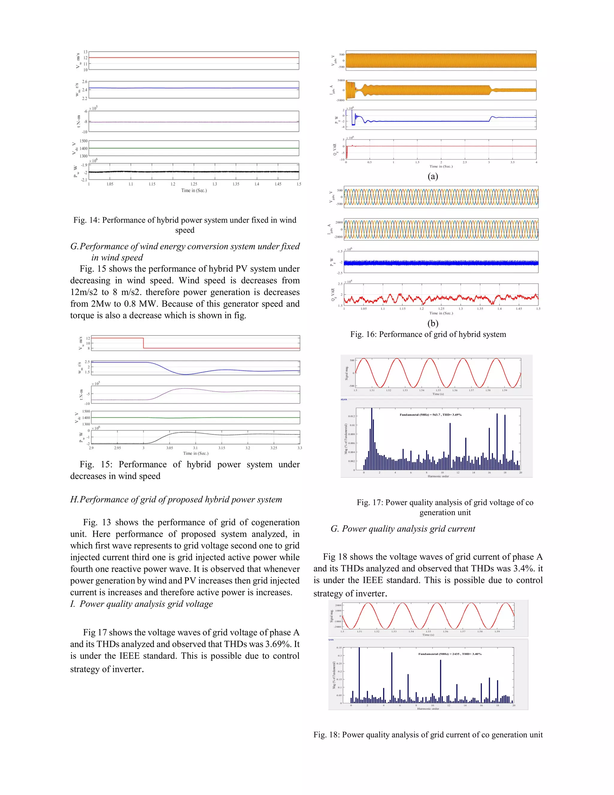
![side converter to improve the performance, yet simple and
efficient to interface both the wind and PV generators into the
utility-grid.
II.MODELING OF PROPOSED SYSTEM
As shown in Fig. 1, the proposed system consists of a
voltage source converter (VSC) to interface the wind
generator, and a voltage source inverter (VSI) to connect the
cogeneration system into the utility-grid. The PV generator is
connected with dc link through the boost dc-dc converter to
extract maximum power. The VSC and VSI are two-level
converters consisting of six cells; each comprises an
insulated-gate-bipolar transistor (IGBT) in parallel with a
diode. In the following subsections, the complete modeling of
the proposed system is provided.
A.Wind turbine modeling
A full-scale wind turbine (FSWT) utilizing a permanent
magnet synchronous generator (PMSG) is selected for its low
maintenance and low operational cost [10]. In wind energy
conversion system (WECS) wind potential energy is
converted into electrical energy with the help of wind turbine
and generator, in proposed paper permanent magnet
synchronous generator is used to convert mechanical energy
to electrical energy. In modeling of WECS following key
equations are used,
Power contains in the undisturbed wind is in form of
kinetic energy then the power is,
21
2
E mv (1)
Where m and v are rate of flow of wind and speed of
undisturbed wind respectively, and the rate of flow of wind is
the function of air density, area through wind is passing and
speed of wind then the power contains in undisturbed wind
can be also written as,
31
2
P Av (2)
Where ρ and A are the density of wind and swept area of
wind turbine respectively
Power output from the wind turbine is given as,
31
2
p
P Av C (3)
3
21
2
p
R
P R C
(4)
Where λ is tip speed ratio it is depends on wind speed
length of blade and generator angular speed in the case of
direct driven wind turbine. And Cp is the betz limit its
optimums value is 0.49. Characteristic of wind turbine is
shown in Fig. 1
B.Modeling of Permanent Magnet Synchronous Generator
(PMSG)
To analysis equivalent circuit of PMSG normally modeled
in synchronous reference frame. To model PMSG rotor
circuit there is no field winding so it can be replaced with
constant current source with fixed magnitude
The following mathematical manipulation can be done.
The voltage equation of PMSG in synchronous reference
frame is given by
Fig. 1Wind turbine characteristic
Fig.2 Equivalent circuit of PMSG in synchronous reference frame
(I R )ds
ds ds s r qs
d
V
dt
(5)
(I R )
qs
qs qs s r ds
d
V
dt
(6)
C. Modeling of photovoltaic system
Photovoltaic system is manly depends on PV module which
is consist with PV cell equivalent circuit of PV cell is given in
Fig. 3
Fig. 3 The equivalent circuit of PV cell
Current equation of PV module are given as,](https://image.slidesharecdn.com/ijsred-v2i5p86-200209151254/75/Analysis-of-Design-and-Control-of-Sustainable-Energy-Based-Hybrid-Power-System-2-2048.jpg)
![VI. CONCLUSION
This paper has presented the sustainable energy based
hybrid power systems using current-controlled
grid-connected VSIs. The VSC at the wind generator-side is
responsible for extracting the maximum wind power
following the wind speed variations. On the utility-grid side,
the role of the VSI is synchronizing with the grid in terms of
phase sequence, grid frequency and voltage magnitude. The
extract of the maximum PV power from the PV generator,
achieve the maximum power by P&O techniques with the
help of dc-dc boost converter and to maintain the dc link
voltage VSI control is responsible a unity PCC voltage under
different modes of operation. Different control techniques for
proposed system such as PV mppt, WECS MPPT control.
And Inverter control and it performance is validated through
the MATLAB Simulink 2015a.
APPENDIX
Proposed system parameters are given in Table.
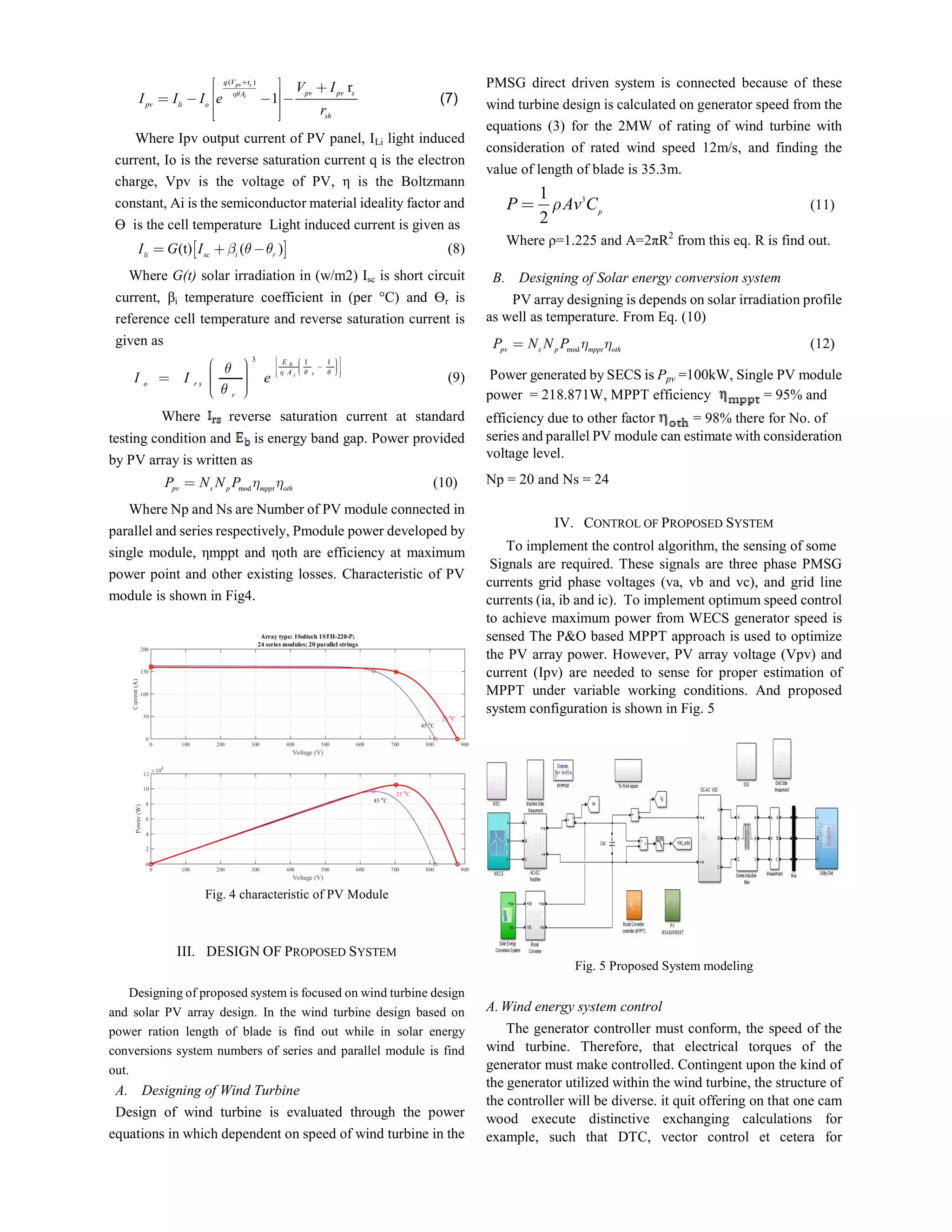
Table 1 PV specifications
Variable Description Value
PPV Rated power 218W
VOC Open circuit voltage 36.6V
ISC Short circuit current 7.97A
VPVM MPPT voltage 29.3V
IPVM MPPT current 7.47A
Ns Number of series module 20
NP Number of parallel module 24
Table 2 Boost converter Specification
VARIABLE DESCRIPTION VALUE
LC INDUCTOR 8.5MH
CC CAPACITANCE 5000ΜF
FC SWITCHING FREQUENCY 10KHZ
Table 3 Parameters of PMSG
VARIABLE DESCRIPTION VALUE
P RATED POWER 2MW
VLM NOMINAL VOLTAGE 690 V
F NOMINAL FREQUENCY 9.75 HZ
STATOR RESISTANCE 0.821 MΩ
D-AXIS ARMATURE
INDUCTANCE
1.5731 MH
Q-AXIS ARMATURE
INDUCTANCE
5.839MH
J INERTIA 20000 KG.M
2
NR RATED SPEED 22.5 RPM
P POLE PAIR 26
Table 4 Parameters of wind turbine
VARIABLE DESCRIPTION VALUE
P RATED ACTIVE POWER
OUTPUT (MW)
2
S RATED APPARENT POWER
(MVAR)
2.2
Τ RATED WIND TURBINE
TORQUE (KN.M)
848.8
ω RATED TURBINE SPEED
(RPM)
22.5
Blade radius (m) 35.3
REFERENCES
[1] F. Blaabjerg, R. Teodorescu, M. Liserre, and A. V. Timbus,
"Overview of Control and Grid Synchronization for
Distributed Power Generation Systems," Industrial
Electronics, IEEE Transactions on, vol. 53, pp. 1398-1409,
2006.
[2] G. H. Bode, L. Poh Chiang, M. J. Newman, and D. G. Holmes,
"An improved robust predictive current regulation algorithm,"
Industry Applications, IEEE Transactions on, vol. 41, pp.
1720-1733, 2005.
[3] A. Rashid, N. Hasan, K. T. Parvez and M. N. I. Maruf, “Study
and analysis of a small scale micro-grid using renewable
energy resources,” Proceedings of Inter. Conf. on Electrical
Engineering and Information Communication Technology
(ICEEICT), Dhaka, 2015.
[4] M. Pichan, H. Rastegar and M. Monfared, “Deadbeat Control
of the Stand-Alone Four-Leg Inverter Considering the Effect of
the Neutral Line Inductor”, IEEE Trans. Ind. Electron., vol.
64, no. 5, pp. 2592 - 2601, Nov. 2017
[5] P. Rodríguez, A. Luna, R. S. Muñoz-Aguilar, I.
Etxeberria-Otadui, R. Teodorescu and F. Blaabjerg, “A
stationary reference frame grid synchronization system for
three-phase grid-connected power converters under adverse
grid conditions,” IEEE Trans. Power Electron., vol. 27, no. 1,
pp. 99–112, Jan. 2012
[6] Fatih Cingoz, Ali Elrayyah, and Yilmaz Sozer, “Optimized
Settings of Droop Parameters Using Stochastic Load Modeling
for Effective DC Microgrids Operation,” IEEE Trans. Industry
Applications, vol. 53, no. 2, pp. 1358 – 1371, 2017.
[7] M. Rezkallah, A. Chandra, B. Singh and S. Singh, “Microgrid
Configurations, Control and Applications,” IEEE
Transactions on Smart Grid, Early Acess, 2018.
[8] P. Roshanfekr, S. Lundmark, T. Thiringer, and M. Alatalo, “A
synchronous reluctance generator for a wind
application-compared with an interior mounted permanent
magnet synchronous generator,” Proceedings in 7th IET Inter.
Conference on Power Electronics, Machines and Drives
(PEMD 2014 , Manchester, pp. 1-5, 2014.
[9] Z.M. Dalala, Z.U. Zahid, and Lai Jih-Sheng, “New Overall
Control Strategy for Small-Scale WECS in MPPT and Stall
Regions with Mode Transfer Control,” IEEE Trans. Energy
Conversion, vol.28, no.4, pp.1082-1092, Dec. 2013.
[10] G. Pathak, B. Singh, and B. K. Panigrahi, “Back Propagation
Algorithm Based Controller for Autonomous Wind-DG
Microgrid,” IEEE Trans. Industry Applications, vol. 52, no. 5,
pp. 4408-4415, Sept.-Oct. 2016.
[11] F. Blaabjerg, Z. Chen, and S. B. Kjaer, “Power electronics as
efficien interface in dispersed power generation systems,”
IEEE Trans. Power Electron., vol. 19, no. 5, pp. 1184-1194,
2004
[12] A. Radwan and Y. Mohamed, "Grid-Connected Wind-Solar
Cogeneration Using Back-to-Back Voltage Source
Converters," in IEEE Transactions on Sustainable Energy.
2019.](https://image.slidesharecdn.com/ijsred-v2i5p86-200209151254/75/Analysis-of-Design-and-Control-of-Sustainable-Energy-Based-Hybrid-Power-System-7-2048.jpg)


This document presents a new control strategy for grid synchronization of a sustainable energy-based hybrid power system consisting of a wind turbine with a permanent magnet synchronous generator and a photovoltaic solar generator. The wind turbine and solar generator harvest sustainable energy which is converted to electrical power and interfaced to the grid via back-to-back voltage source converters. The control strategy aims to maximize power extraction from both generators while providing smooth sinusoidal voltages to the grid with fixed frequency and minimizing total harmonic distortion. The system and control algorithms are modeled and validated through MATLAB simulations.


![6.[36 45]seven level modified cascaded inverter for induction motor drive app...](https://cdn.slidesharecdn.com/ss_thumbnails/6-36-45sevenlevelmodifiedcascadedinverterforinductionmotordriveapplications-111118181646-phpapp02-thumbnail.jpg?width=640&height=640&fit=bounds)