Download to read offline
![World Academy of Science, Engineering and Technology
International Journal of Electrical, Electronic Science and Engineering Vol:2 No:9, 2008
Real-Coded Genetic Algorithm for Robust
Power System Stabilizer Design
Sidhartha Panda and C. Ardil
International Science Index 21, 2008 waset.org/publications/15177
Abstract—Power system stabilizers (PSS) are now routinely used
in the industry to damp out power system oscillations. In this paper,
real-coded genetic algorithm (RCGA) optimization technique is
applied to design robust power system stabilizer for both singlemachine infinite-bus (SMIB) and multi-machine power system. The
design problem of the proposed controller is formulated as an
optimization problem and RCGA is employed to search for optimal
controller parameters. By minimizing the time-domain based
objective function, in which the deviation in the oscillatory rotor
speed of the generator is involved; stability performance of the
system is improved. The non-linear simulation results are presented
under wide range of operating conditions; disturbances at different
locations as well as for various fault clearing sequences to show the
effectiveness and robustness of the proposed controller and their
ability to provide efficient damping of low frequency oscillations.
Keywords—Particle swarm optimization, power system
stabilizer, low frequency oscillations, power system stability.
I. INTRODUCTION
L
OW frequency oscillations are observed when large power
systems are interconnected by relatively weak tie lines.
These oscillations may sustain and grow to cause system
separation if no adequate damping is available [1]. Power
system stabilizers (PSS) are now routinely used in the industry
to damp out oscillations. An appropriate selection of PSS
parameters results in satisfactory performance during system
disturbances [2].
The problem of PSS parameter tuning is a complex
exercise. A number of conventional techniques have been
reported in the literature pertaining to design problems of
conventional power system stabilizers namely: the eigenvalue
assignment, mathematical programming, gradient procedure
for optimization and also the modern control theory [3].
Unfortunately, the conventional techniques are time
consuming as they are iterative and require heavy computation
burden and slow convergence. In addition, the search process
_____________________________________________
Sidhartha Panda is with Associate Professor, Department of Electrical
Engineering, School of Technology, KIIT University, Bhubaneswar-751024,
Orissa, INDIA. (.e-mail: panda_sidhartha@rediffmail.com Phone: +919438251162).
C. Ardil is with National Academy of Aviation, AZ1045, Baku,
Azerbaijan, Bina, 25th km, NAA (e-mail: cemalardil@gmail.com).
is susceptible to be trapped in local minima and the solution
obtained may not be optimal [4]. Most of the proposals on
PSS parameter tuning are based on small disturbance analysis
that required linearization of the system involved. However,
linear methods cannot properly capture complex dynamics of
the system, especially during major disturbances. This
presents difficulties for tuning the PSS in that the controller
tuned to provide desired performance at small signal condition
do not guarantee acceptable performance in the event of major
disturbances. In order to overcome the above short comings,
this paper uses three-phase non-linear models of power system
components and to optimally tune the PSS parameters.
Also, the controller should provide some degree of
robustness to the variations loading conditions, and
configurations as the machine parameters change with
operating conditions. A set of controller parameters which
stabilize the system under a certain operating condition may
no longer yield satisfactory results when there is a drastic
change in power system operating conditions and
configurations [5].
The evolutionary methods constitute an approach to search
for the optimum solutions via some form of directed random
search process. A relevant characteristic of the evolutionary
methods is that they search for solutions without previous
problem knowledge. Recently, Genetic Algorithm (GA)
appeared as a promising evolutionary technique for handling
the optimization problems [6]. GA has been popular in
academia and the industry mainly because of its intuitiveness,
ease of implementation, and the ability to effectively solve
highly nonlinear, mixed integer optimisation problems that are
typical of complex engineering systems. In view of the above,
this paper proposes to use GA optimization technique for the
design of robust PSS.
A comprehensive assessment of the effects of PSS-based
damping controller for both single-machine infinite-bus
(SMIB) and multi-machine power system has been carried out
in this paper. The design problem of the proposed controller is
transformed into an optimization problem. The design
objective is to improve the stability the power system,
subjected to severe disturbances. GA based optimal tuning
algorithm is used to optimally tune the parameters of the PSS.
The proposed controller has been applied and tested under
wide range of operating conditions; disturbances at different
locations as well as for various fault clearing sequences to
show the effectiveness and robustness of the proposed
44](https://image.slidesharecdn.com/real-coded-genetic-algorithm-for-robust-power-system-stabilizer-design-140127055450-phpapp02/85/Real-coded-genetic-algorithm-for-robust-power-system-stabilizer-design-1-320.jpg)
![World Academy of Science, Engineering and Technology
International Journal of Electrical, Electronic Science and Engineering Vol:2 No:9, 2008
Real-Coded Genetic Algorithm for Robust
Power System Stabilizer Design
Sidhartha Panda and C. Ardil
International Science Index 21, 2008 waset.org/publications/15177
Abstract—Power system stabilizers (PSS) are now routinely used
in the industry to damp out power system oscillations. In this paper,
real-coded genetic algorithm (RCGA) optimization technique is
applied to design robust power system stabilizer for both singlemachine infinite-bus (SMIB) and multi-machine power system. The
design problem of the proposed controller is formulated as an
optimization problem and RCGA is employed to search for optimal
controller parameters. By minimizing the time-domain based
objective function, in which the deviation in the oscillatory rotor
speed of the generator is involved; stability performance of the
system is improved. The non-linear simulation results are presented
under wide range of operating conditions; disturbances at different
locations as well as for various fault clearing sequences to show the
effectiveness and robustness of the proposed controller and their
ability to provide efficient damping of low frequency oscillations.
Keywords—Particle swarm optimization, power system
stabilizer, low frequency oscillations, power system stability.
I. INTRODUCTION
L
OW frequency oscillations are observed when large power
systems are interconnected by relatively weak tie lines.
These oscillations may sustain and grow to cause system
separation if no adequate damping is available [1]. Power
system stabilizers (PSS) are now routinely used in the industry
to damp out oscillations. An appropriate selection of PSS
parameters results in satisfactory performance during system
disturbances [2].
The problem of PSS parameter tuning is a complex
exercise. A number of conventional techniques have been
reported in the literature pertaining to design problems of
conventional power system stabilizers namely: the eigenvalue
assignment, mathematical programming, gradient procedure
for optimization and also the modern control theory [3].
Unfortunately, the conventional techniques are time
consuming as they are iterative and require heavy computation
burden and slow convergence. In addition, the search process
_____________________________________________
Sidhartha Panda is with Associate Professor, Department of Electrical
Engineering, School of Technology, KIIT University, Bhubaneswar-751024,
Orissa, INDIA. (.e-mail: panda_sidhartha@rediffmail.com Phone: +919438251162).
C. Ardil is with National Academy of Aviation, AZ1045, Baku,
Azerbaijan, Bina, 25th km, NAA (e-mail: cemalardil@gmail.com).
is susceptible to be trapped in local minima and the solution
obtained may not be optimal [4]. Most of the proposals on
PSS parameter tuning are based on small disturbance analysis
that required linearization of the system involved. However,
linear methods cannot properly capture complex dynamics of
the system, especially during major disturbances. This
presents difficulties for tuning the PSS in that the controller
tuned to provide desired performance at small signal condition
do not guarantee acceptable performance in the event of major
disturbances. In order to overcome the above short comings,
this paper uses three-phase non-linear models of power system
components and to optimally tune the PSS parameters.
Also, the controller should provide some degree of
robustness to the variations loading conditions, and
configurations as the machine parameters change with
operating conditions. A set of controller parameters which
stabilize the system under a certain operating condition may
no longer yield satisfactory results when there is a drastic
change in power system operating conditions and
configurations [5].
The evolutionary methods constitute an approach to search
for the optimum solutions via some form of directed random
search process. A relevant characteristic of the evolutionary
methods is that they search for solutions without previous
problem knowledge. Recently, Genetic Algorithm (GA)
appeared as a promising evolutionary technique for handling
the optimization problems [6]. GA has been popular in
academia and the industry mainly because of its intuitiveness,
ease of implementation, and the ability to effectively solve
highly nonlinear, mixed integer optimisation problems that are
typical of complex engineering systems. In view of the above,
this paper proposes to use GA optimization technique for the
design of robust PSS.
A comprehensive assessment of the effects of PSS-based
damping controller for both single-machine infinite-bus
(SMIB) and multi-machine power system has been carried out
in this paper. The design problem of the proposed controller is
transformed into an optimization problem. The design
objective is to improve the stability the power system,
subjected to severe disturbances. GA based optimal tuning
algorithm is used to optimally tune the parameters of the PSS.
The proposed controller has been applied and tested under
wide range of operating conditions; disturbances at different
locations as well as for various fault clearing sequences to
show the effectiveness and robustness of the proposed
44](https://image.slidesharecdn.com/real-coded-genetic-algorithm-for-robust-power-system-stabilizer-design-140127055450-phpapp02/75/Real-coded-genetic-algorithm-for-robust-power-system-stabilizer-design-1-2048.jpg)
![World Academy of Science, Engineering and Technology
International Journal of Electrical, Electronic Science and Engineering Vol:2 No:9, 2008
controller and their ability to provide efficient damping of low
frequency oscillations.
This paper is organized as follows. In Section II, the power
systems under study are presented. The proposed controller
structure and problem formulation is described in Section III.
A short overview of GA is presented in Section IV. Simulation
results are provided and discussed in Section V and
conclusions are given in Section VI.
International Science Index 21, 2008 waset.org/publications/15177
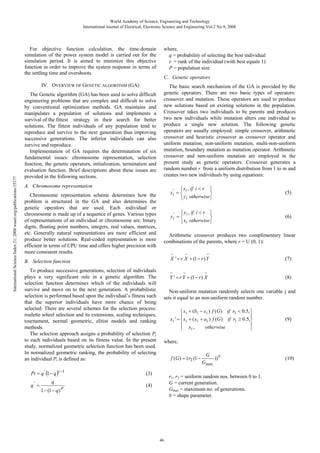
II. POWER SYSTEMS UNDER STUDY
The SMIB power system shown in Fig. 1and the multimachine system shown in Fig. 2 are considered in this study
for the design of robust PSS. The SMIB system comprises a
generator connected to an infinite bus through a step-up
transformer followed by a double circuit transmission line. In
the figure T represents the transformer; VT and VB are the
generator terminal and infinite bus voltage respectively; I is
the line current and PL is the real power flow in the
transmission lines. The generator is equipped with hydraulic
turbine & governor (HTG), excitation system and a power
system stabilizer. The multi-machine system consists of three
generators divided in to two subsystems and are connected via
an intertie. Following a disturbance, the two subsystems swing
against each other resulting in instability. To improve the
reliability the line is sectionalized. In Fig. 2, G1, G2 and G3
represent the generators; T/F1 - T/F3 represent the transformers
and L1, L2 and L3 represent the line sections respectively. The
generators are equipped with hydraulic turbine & governor
(HTG), excitation system and power system stabilizer. All the
relevant parameters are given in appendix.
T
I
Tr. Line
PL
Bus1
PL1
Bus2
Generator
Infinite-bus
and the output is the stabilizing signal VS which is added to
the reference excitation system voltage. The signal washout
block serves as a high-pass filter, with the time constant TW,
high enough to allow signals associated with oscillations in
input signal to pass unchanged. From the viewpoint of the
washout function, the value of TW is not critical and may be in
the range of 1 to 20 seconds [1]. The phase compensation
block (time constants T1, T2 and T3, T4) provides the
appropriate phase-lead characteristics to compensate for the
phase lag between input and the output signals.
Δω
Input
Sensor
L2
Bus5
L1
L1
L1
G3
T/F1
Load1
T/F3
Load3
Output
min
VS
In case of above lead-lag structured PSS, the sensor and the
washout time constants are usually specified. In the present
study, a sensor time constant TSN = 15 ms and washout time
constant TW =10s are used. The controller gain KP and the time
constants T1, T2, T3 and T4 are to be determined.
It is worth mentioning that the proposed controllers are
designed to minimize the power system oscillations after a
large disturbance so as to improve the power system stability.
These oscillations are reflected in the deviations in power
angle, rotor speed and line power. Minimization of any one or
all of the above deviations could be chosen as the objective. In
the present study, an integral time absolute error of the speed
deviations is taken as the objective function for SMIB power
system. For multi-machine power system an integral time
absolute error of the speed signals corresponding to the local
and inter-area modes of oscillations is taken as the objective
function.
Bus1
Bus6
G1
L3
VS
B. Problem Formulation
J=
Load2
Bus3
Two-stage
lead-lag block
max
VS
For SMIB system:
L1
T/F2
Washout
block
1 + sT3
1 + sT4
The objective functions are expressed as:
Bus4
G2
Gain
block
1 + sT1
1 + sT2
Fig. 3 Structure of power system stabilizer
Fig. 1 Single-machine infinite-bus power system
Bus2
KP
sTW
1 + sTW
Load4
J=
The structure of PSS, to modulate the excitation voltage is
shown in Fig. 3. The structure consists of a sensor, a gain
block with gain KP, a signal washout block and two-stage
phase compensation blocks as shown in Fig. 3. The input
signal of the proposed controller is the speed deviation (∆ω),
(1)
t = t sim
∫ ( ∑ Δω L + ∑ Δω I ) ⋅ t ⋅ dt
(2)
t =0
Fig. 2 Multi-machine power system
A. Structure of Power System Stabilizer
∫ [ | Δω | ] ⋅ t.dt
t =0
For multi-machine system:
L1
III. THE PROPOSED APPROACH
t =t sim
Where, Δω denotes the speed deviation of SMIB system
generator; ΔωL and ΔωI are the speed deviations of inter-area
and local modes of oscillations respectively and tsim is the time
range of the simulation. In the present three-machine study,
the local mode ΔωL is (ω2- ω3), and the inter-area mode ΔωI is
[(ω2- ω1) + (ω3- ω1)], where ω1 , ω2 and ω3 are the speed
deviations of machines, 1 2 and 3 respectively.
45](https://image.slidesharecdn.com/real-coded-genetic-algorithm-for-robust-power-system-stabilizer-design-140127055450-phpapp02/85/Real-coded-genetic-algorithm-for-robust-power-system-stabilizer-design-2-320.jpg)
![World Academy of Science, Engineering and Technology
International Journal of Electrical, Electronic Science and Engineering Vol:2 No:9, 2008
D. Initialization, termination and evaluation function
An initial population is needed to start the genetic algorithm
procedure. The initial population can be randomly generated
or can be taken from other methods.
The GA moves from generation to generation until a
stopping criterion is met. The stopping criterion could be
maximum number of generations, population convergence
criteria, lack of improvement in the best solution over a
specified number of generations or target value for the
objective function.
Evaluation functions or objective functions of many forms
can be used in a GA so that the function can map the
population into a partially ordered set. The computational
flowchart of the GA optimization process employed in the
present study is given in Fig. 4.
A. Single-Machine Infinite-Bus Power System
Start
In order to optimally tune the parameters of the PSS, as well
as to assess its performance and robustness under wide range
of operating conditions with various fault disturbances and
fault clearing sequences, the test system depicted in Fig. 1 is
considered at the first instant. The model of the example
power system shown in Fig. 1 is developed using SPS
blockset. The system consists of a of 2100 MVA, 13.8 kV,
60Hz hydraulic generating unit, connected to a 300 km long
double-circuit transmission line through a 3-phase 13.8/500
kV step-up transformer and a 100 MVA SSSC. The generator
is equipped with Hydraulic Turbine & Governor (HTG) and
Excitation system. All the relevant parameters are given in
appendix.
International Science Index 21, 2008 waset.org/publications/15177
Specify the parameters for GA
Generate initial population
Gen.=1
Time-domain simulation of
power system model
Find the fitness of each
individual in the current
population
Gen.=Gen.+1
Gen. > Max. Gen.?
resulting from the interaction of linear R, L, C elements and
distributed parameter lines are of no interest. These oscillation
modes, which are usually located above the fundamental
frequency of 50 Hz or 60 Hz, do not interfere with the slow
machine modes and regulator time constants. The phasor
solution method is used here where these fast modes are
ignored by replacing the network's differential equations by a
set of algebraic equations. The state-space model of the
network is replaced by a transfer function evaluated at the
fundamental frequency and relating inputs (current injected by
machines into the network) and outputs (voltages at machine
terminals). The phasor solution method uses a reduced statespace model consisting of slow states of machines, turbines,
and regulators, thus dramatically reducing the required
simulation time. In view of the above, the phasor solution
method is used in the present study.
Yes
B. Application of GA
Stop
No
Apply GA operators:
selection,crossover and
mutation
Fig. 4 Flowchart of genetic algorithm
V. RESULTS AND DISCUSSIONS
The SimPowerSystems (SPS) toolbox is used for all
simulations and PSS design. SPS is a MATLAB-based
modern design tool that allows scientists and engineers to
rapidly and easily build models to simulate power systems
using Simulink environment. The SPS’s main library,
powerlib, contains models of typical power equipment such as
machines, governors, excitation systems, transformers, and
transmission lines. The library also contains the Powergui
block that opens a graphical user interface for the steady-state
analysis of electrical circuits. The Load Flow and Machine
Initialization option of the Powergui block performs the load
flow and the machines initialization [7].
In power system stability study, the fast oscillation modes
For the purpose of optimization of equation (1), RCGA is
employed. The objective function is evaluated for each
individual by simulating the example power system,
considering a severe disturbance. For objective function
calculation, a 3-phase short-circuit fault in one of the parallel
transmission lines is considered. For the implementation of
GA normal geometric selection is employed which is a
ranking selection function based on the normalised geometric
distribution. Arithmetic crossover takes two parents and
performs an interpolation along the line formed by the two
parents. Non uniform mutation changes one of the parameters
of the parent based on a non-uniform probability distribution.
This Gaussian distribution starts wide, and narrows to a point
distribution as the current generation approaches the
maximum generation. The optimization was performed with
the total number of generations set to 100. Table I shows the
optimal values of PSS parameters obtained by the GA for
SMIB system. The convergence rate of objective function J
with the number of generations is shown in Fig. 5.
TABLE I
OPTIMIZED PSS PARAMETERS FOR SMIB SYSTEM
KP
47
T1
T2
T3
T4
48.0988
0.0585
0.022
3.6177
4.8472](https://image.slidesharecdn.com/real-coded-genetic-algorithm-for-robust-power-system-stabilizer-design-140127055450-phpapp02/85/Real-coded-genetic-algorithm-for-robust-power-system-stabilizer-design-4-320.jpg)
![World Academy of Science, Engineering and Technology
International Journal of Electrical, Electronic Science and Engineering Vol:2 No:9, 2008
-4
10.5
x 10
55
45
δ (deg)
50
9.5
Fitness
10
9
CPSS
0
20
40
60
80
100
0
6
8
10
2000
PL (MW)
1500
1000
NC
CPSS
GAPSS
500
0
2
4
6
8
10
Time (sec)
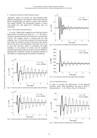
Case I: Nominal loading:
A 3-cycle 3-phase fault is applied at the middle of one
transmission line at nominal loading condition (Pe = 0.75 pu,
δ0 = 45.360). The fault is cleared by tripping of the faulty line
and the line is reclosed after 3-cycles. The original system is
restored after the line reclosure. The system response for the
above contingency is shown in Figs. 6-8. It is clear from these
Figs. that, the system is poorly damped without control under
this disturbance.
Fig. 8 Tie-line power flow response of for 3-cycle 3-phase fault at
middle of transmission line with nominal loading condition
Power system oscillations are effectively suppressed with the
application of conventional power system stabilizer. It is also
clear from Figs. that, the proposed RCGA optimized PSS out
perform the conventional PSS from dynamic performance
point of view. The power system oscillations are quickly
damped out with the application of proposed GPSS.
Case II: Heavy loading:
-3
x 10
2
Δ ω (pu)
4
Fig. 7 Power angle response of for 3-cycle 3-phase fault at middle of
transmission line with nominal loading condition
To assess the effectiveness and robustness of the proposed
controller, simulation studies are carried out for various fault
disturbances and fault clearing sequences. The behavior of the
proposed controller under transient conditions is verified by
applying various types of disturbances under different
operating conditions. In all the Figs., the response without
control (no control) is shown with dotted line with legend NC;
the response with conventionally designed power system
stabilizer [1] is shown with dashed lines with legend CPSS
and the response with proposed RCGA optimized PSS is
shown with solid line with legend GPSS respectively. The
following cases are considered:
0
-2
NC
CPSS
GAPSS
-4
0
2
Time (sec)
C. Simulation Results for SMIB Power System
International Science Index 21, 2008 waset.org/publications/15177
GAPSS
30
Generations
Fig. 5 Convergence of fitness value for SMIB power system
4
NC
35
8.5
8
40
2
4
6
8
10
Time (sec)
Fig. 6 Speed deviation response of for 3-cycle 3-phase fault at middle
of transmission line with nominal loading condition
To test the robustness of the controller to operating
condition and fault clearing sequence, the generator loading is
changed to heavy loading condition (Pe = 1.0 pu, δ0 = 60.720),
and a 3-cycle, 3-phase fault is applied at Bus2. The fault is
cleared by opening both the lines. The lines are reclosed after
3-cycles and original system is restored. The system response
for the above severe disturbance is shown in Figs. 9-10. It can
be clearly seen from these Figs. that, for the given operating
condition and contingency, the system is unstable without
control. Stability of the system is maintained and power
system oscillations are effectively damped out with the
application of conventional PSS. The proposed PSS provides
the best performance and outperform the conventional PSS by
minimizing the transient errors and quickly stabilizes the
system.
48](https://image.slidesharecdn.com/real-coded-genetic-algorithm-for-robust-power-system-stabilizer-design-140127055450-phpapp02/85/Real-coded-genetic-algorithm-for-robust-power-system-stabilizer-design-5-320.jpg)
![World Academy of Science, Engineering and Technology
International Journal of Electrical, Electronic Science and Engineering Vol:2 No:9, 2008
proposed PSS is robust to type of disturbance and provides
efficient damping to power system oscillations even under
small disturbance. The dynamic performance of the proposed
GPSS is also superior to that of conventional CPSS.
0.015
0.01
Δ ω (pu)
0.005
D. Multi-Machine Power System
0
-0.005
-0.01
-0.015
NC
CPSS
GAPSS
-0.02
-0.025
0
2
4
6
8
10
Time (sec)
Fig. 9 Speed deviation response of for 3-cycle 3-phase fault at Bus2
with heavy loading condition
3000
Machine 1 generation: Pe1 = 3480.6 MW (0.8287 pu); Qe1
= 2577.2 MVAR (0.6136 pu)
PL (MW)
2000
Machine 2 generation: Pe2 = 1280 MW (0.6095pu); Qe2 =
444.27 MVAR (0.2116 pu)
1000
Machine 3 generation: Pe3 = 880 MW (0.419pu); Qe3 =
256.33 MVAR (0.1221 pu)
0
-1000
NC
CPSS
GAPSS
0
2
4
6
8
10
Time (sec)
Fig. 10 Tie-line power flow response of for 3-cycle 3-phase fault at
Bus2 with heavy loading condition
The same approach as explained for SMIB case is followed
to optimize the three power system stabilizers assumed to be
installed for three generators. Convergence rate of objective
function J with the number of generations is shown in Fig. 12.
The optimized values of the PSSs are shown in Table II.
-4
-3
1
1.3
x 10
x 10
1.2
Fitness
0.5
Δ ω (pu)
International Science Index 21, 2008 waset.org/publications/15177
The proposed approach of designing and optimizing the
parameters of PSS is also extended to a multi-machine power
system shown in Fig. 2. It is similar to the power systems used
in references [8-9]. The system consists of three generators
divided in to two subsystems and are connected via an intertie.
Following a disturbance, the two subsystems swing against
each other resulting in instability. The relevant data for the
system is given in appendix A.
Load flow is performed with machine 1 as swing bus and
machines 2 and 3 as a PV generation buss. The initial
operating conditions used are:
0
1
0.9
-0.5
NC
CPSS
GAPSS
-1
1.1
0
1
2
3
4
5
6
0.8
7
Time (sec)
Fig. 11 Speed deviation response of for 100 ms load rejection at Bus2
0
20
40
60
80
Generations
Fig. 12 Convergence of fitness value for multi-machine system
TABLE II
OPTIMIZED PSS PARAMETERS FOR MULTI-MACHINE SYSTEM
Case III: Small disturbance:
Parameters
PSS-1
PSS-1
31.8276
40.5438
34.2573
T1
0.0778
0.0205
0.0727
T2
0.0444
0.0283
0.0564
T3
3.6471
3.8237
3.1789
T4
49
PSS-1
KP
In order to examine the effectiveness of the proposed
controller under small disturbance, the load at Bus2 is
disconnected at t = 1 sec for 100 ms (This simulates a small
disturbance). Fig. 11 shows the system speed deviation
response for the above contingency. It is clear from Fig. 11
that, the system is poorly damped without control under this
small disturbance. It is also evident from Fig. 11 that the
5.5578
5.7608
5.9391
100](https://image.slidesharecdn.com/real-coded-genetic-algorithm-for-robust-power-system-stabilizer-design-140127055450-phpapp02/85/Real-coded-genetic-algorithm-for-robust-power-system-stabilizer-design-6-320.jpg)
![World Academy of Science, Engineering and Technology
International Journal of Electrical, Electronic Science and Engineering Vol:2 No:9, 2008
variations of the inter-area and local modes of oscillations
against time, and the tie-line power flow from which it is clear
that the proposed controllers damps the modal oscillations
effectively even for small disturbance.
-3
NC
ω2 - ω3 (pu)
GAPSSs
Single-machine Infinite Bus Power System:
0.5
0
-0.5
-1
0
2
4
6
8
10
Time (sec)
Fig. 18 Local mode of oscillation for small disturbance
2400
Generator: SB = 2100 MVA, H =3.7 s, VB = 13.8 kV, f = 60
Hz, RS = 2.8544 e -3, Xd =1.305, Xd’= 0.296, Xd’’= 0.252, Xq =
0.474, Xq’ = 0.243, Xq’’ = 0.18, Td =1.01 s, Td’= 0.053 s, Tqo’’=
0.1 s.
Load at Bus2: 250MW
Transformer: 2100 MVA, 13.8/500 kV, 60 Hz, R1 =R2=
0.002, L1 = 0,L2=0.12, D1/Yg connection, Rm = 500, Lm = 500
Transmission line: 3-Ph, 60 Hz, Length = 300 km each, R1 =
0.02546 Ω/ km, R0= 0.3864 Ω/ km, L1= 0.9337e-3 H/km, L0 =
4.1264e-3 H/ km, C1 = 12.74e-9 F/ km, C0 = 7.751e-9 F/ km
Conventional power system stabilizer
Sensor time constant =15 ms, TW= 10 s, T1=0.05 s,
T2=0.02 s T3=3 s, T4=5.4 s, Output limits of VS = ± 0.15
Three-machine Power System:
2200
2000
PL (MW)
International Science Index 21, 2008 waset.org/publications/15177
APPENDIX
A complete list of parameters used appears in the default
options of SimPowerSystems in the User’s Manual [15]. All
data are in pu unless specified otherwise.
x 10
1
effectiveness and robustness of the proposed RCGA optimized
PSS controller and their ability to provide efficient damping of
low frequency oscillations.
1800
1600
1400
1200
1000
NC
GAPSSs
800
0
2
4
6
8
10
Time (sec)
Fig. 19 Tie-line power flow for small disturbance
VI. CONCLUSION
In this paper, power system stability enhancement by power
system stabilizer is presented. For the proposed controller
design problem, a non-liner simulation-based objective
function to increase the system damping was developed. Then,
the real coded genetic algorithm optimization technique is
implemented to search for the optimal controller parameters.
The effectiveness of the proposed controller, for power system
stability improvement, is demonstrated for both singlemachine infinite-bus and multi-machine power system
subjected to various disturbances. The dynamic performance
of proposed PSS has also been compared with a
conventionally designed PSS to show its superiority. The nonlinear simulation results presented under wide range of
operating conditions; disturbances at different locations as
well as for various fault clearing sequences, show the
Generators: SB1 = 4200 MVA, SB2 = SB3 = 2100 MVA, H
=3.7 s, VB = 13.8 kV, f = 60 Hz, RS = 2.8544 e -3, Xd =1.305,
Xd’= 0.296, Xd’’= 0.252, Xq = 0.474, Xq’ = 0.243, Xq’’ = 0.18, Td
= 1.01 s, Td’ = 0.053 s, Tqo’’= 0.1 s.
Loads:
Load1=7500MW+1500MVAR,
Load2=Load3=25MW, Load4=250MW
Transformers: SBT1=2100MVA, SBT2= SBT2=2100MVA,
13.8/500 kV, f = 60 Hz, R1 =R2= 0.002, L1 = 0, L2=0.12, D1/Yg
connection, Rm = 500, Lm = 500
Transmission lines: 3-Ph, 60 Hz, Line lengths: L1 = 175
km, L2=50 km, L3=100 km, R1 = 0.02546 Ω/ km, R0= 0.3864
Ω/ km, L1= 0.9337e-3 H/km, L0 = 4.1264e-3 H/ km, C1 =
12.74e-9 F/ km, C0 = 7.751e-9 F/ km
Hydraulic Turbine and Governor: Ka = 3.33, Ta = 0.07, Gmin
= 0.01, Gmax = 0.97518, Vgmin = - 0.1 pu/s, Vgmax = 0.1 pu/s, Rp
= 0.05, Kp = 1.163, Ki = 0.105, Kd = 0, Td = 0.01 s,β =0, Tw =
2.67 s
Excitation System: TLP = 0.02 s, Ka =200, Ta = 0.001 s, Ke
=1, Te =0, Tb = 0, Tc =0, Kf = 0.001, Tf = 0.1 s, Efmin = 0, Efmax =
7, Kp = 0
REFERENCES
[1]
[2]
[3]
51
P. Kundur, Power System Stability and Control. New York: McGrawHill, 1994.
P. Kundur, M. Klein, G. J. Rogers, and M. S. Zywno, “Application of
power system stabilizers for enhancement of overall system stability,”
IEEE Trans. Power Syst., vol. 4, pp. 614–626, 1989.
M. A. Abido , “Pole placement technique for PSS and TCSC-based
stabilizer design using simulated annealing” Electrical Power and
Energy Systems ,vol-22 , pp 543–554, 2000.](https://image.slidesharecdn.com/real-coded-genetic-algorithm-for-robust-power-system-stabilizer-design-140127055450-phpapp02/85/Real-coded-genetic-algorithm-for-robust-power-system-stabilizer-design-8-320.jpg)
![World Academy of Science, Engineering and Technology
International Journal of Electrical, Electronic Science and Engineering Vol:2 No:9, 2008
[4]
[5]
[6]
[7]
[8]
International Science Index 21, 2008 waset.org/publications/15177
[9]
Y.L. Abdel-Magid, M.A. Abido, “Coordinated design of a PSS and a
SVC-based controller to enhance power system stability. Electrical
Power & Energy Syst, vol. 25, pp. 695-704, 2003.
Y.L. Abdel-Magid and M.A.Abido, “Robust coordinated design of
excitation and TCSC-based stabilizers using genetic algorithms,
International Journal of Electrical Power & Energy Systems, vol. 69,
no. 2-3, pp. 129-141. 2004.
D.E.Goldberg, Genetic Algorithms in Search, Optimization and Machine
Learning. Addison-Wesley, 1989.
SimPowerSystems 4.3 User’s Guide,
Available:http://www.mathworks.com/products/simpower/
M.Noroozian, G.Anderson, and K.Tomsovic, “Robust near-optimal
control of power system oscillation with fuzzy logic”, IEEE Trans.
Power Del., Vol. 11, No. 1, pp. 393–400, January 1996.
S.Mishra, P.K.Dash, P.K.Hota, and M.Tripathy, “Genetically optimized
neuro-fuzzy IPFC for damping modal oscillations of power system”,
IEEE Trans. Power Syst.,Vol. 17, No. 4, pp. 1140-1147, November
2002.
Sidhartha Panda received the B.E. degree in Electrical Engineering from
Bangalore University in 1991in first class and M.E. degree in Electrical
Engineering with specialization in Power Systems Engineering from
University College of Engineering, Burla, Sambalpur University, India in
2001. He is presently an Associate Professor in Electrical Engineering
Department, School of Technology, KIIT University, Bhubaneswar, Orissa,
India. He was a Research Scholar in Electrical Engineering Department of
Indian Institute of Technology Roorkee, India and recently submitted the
Ph.D. thesis. Earlier, he was an Associate Professor in the Department of
Electrical and Electronics Engineering, VITAM College of Engineering,
Andhra Pradesh, India and Lecturer in the Department of Electrical
Engineering, SMIT, Orissa, India. He has published more than 35 papers in
international journals and conferences including 23 papers in international
journals. He has also acted as reviewer of some ELSEVIER international
journals (Applied Soft Computing Journal and International Journal of
Electrical Power and Energy Systems). His areas of research include power
system transient stability, power system dynamic stability, FACTS,
optimization techniques, distributed generation and wind energy.
52](https://image.slidesharecdn.com/real-coded-genetic-algorithm-for-robust-power-system-stabilizer-design-140127055450-phpapp02/85/Real-coded-genetic-algorithm-for-robust-power-system-stabilizer-design-9-320.jpg)

This document summarizes a research paper that uses a real-coded genetic algorithm to optimize the design of power system stabilizers. The algorithm is applied to both single-machine and multi-machine power systems. The goal is to minimize rotor speed deviations and improve stability under disturbances. Simulation results show the proposed controller provides effective damping of low frequency oscillations across different operating conditions.