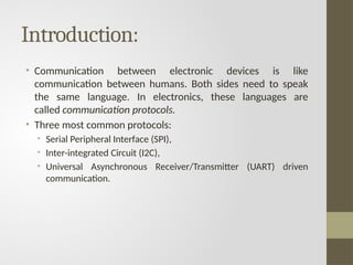
Introduction:
• Communication betweenelectronic devices is like
communication between humans. Both sides need to speak
the same language. In electronics, these languages are
called communication protocols.
• Three most common protocols:
• Serial Peripheral Interface (SPI),
• Inter-integrated Circuit (I2C),
• Universal Asynchronous Receiver/Transmitter (UART) driven
communication.
3.
Contd..
• They arequite a bit slower than protocols like USB, ethernet ,
Bluetooth, and WiFi , but they’re a lot more simple and use
less hardware and system resources.
• SPI, I2C, and UART are ideal for communication between
microcontrollers and between microcontrollers and sensors
where large amounts of high speed data don’t need to be
transferred.
INTRODUCTION TO SPI
COMMUNICATION
•SPI is a common communication protocol used by
many different devices. For example, SD card reader modules,
RFID card reader modules, and 2.4 GHz wireless
transmitter/receivers all use SPI to communicate with
microcontrollers.
• One unique benefit of SPI is the fact that data can be
transferred without interruption. Any number of bits can
be sent or received in a continuous stream.
• With I2C and UART, data is sent in packets, limited to a specific
number of bits. Start and stop conditions define the beginning
and end of each packet, so the data is interrupted during
transmission.
6.
• Devices communicatingvia SPI are in a master-slave
relationship.
• The master is the controlling device (usually a
microcontroller), while the slave (usually a sensor, display, or
memory chip) takes instruction from the master.
• The simplest configuration of SPI is a single master, single slave
system, but one master can control more than one slave
7.
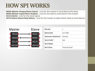
HOW SPI WORKS
MOSI(Master Output/Slave Input) – Line for the master to send data to the slave.
MISO (Master Input/Slave Output) – Line for the slave to send data to the master.
SCLK (Clock) – Line for the clock signal.
SS/CS (Slave Select/Chip Select) – Line for the master to select which slave to send data to.
8.
THE CLOCK
• Theclock signal synchronizes the output of data bits from the master
to the sampling of bits by the slave.
• One bit of data is transferred in each clock cycle, so the speed of data
transfer is determined by the frequency of the clock signal.
• SPI communication is always initiated by the master since the master
configures and generates the clock signal.
• Any communication protocol where devices share a clock signal is
known as synchronous. SPI is a synchronous communication protocol.
• There are also asynchronous methods that don’t use a clock signal.
For example, in UART communication, both sides are set to a pre-
configured baud rate that dictates the speed and timing of data
transmission.
9.
Contd..
• The clocksignal in SPI can be modified using the properties
of clock polarity and clock phase.
• These two properties work together to define when the bits
are output and when they are sampled.
• Clock polarity can be set by the master to allow for bits to be
output and sampled on either the rising or falling edge of the
clock cycle.
• Clock phase can be set for output and sampling to occur on
either the first edge or second edge of the clock cycle,
regardless of whether it is rising or falling.
10.
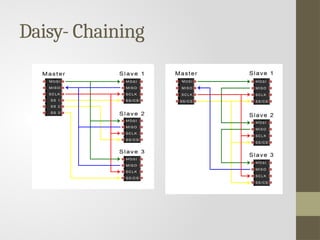
SLAVE SELECT
• Themaster can choose which slave it wants to talk to by
setting the slave’s CS/SS line to a low voltage level.
• In the idle, non-transmitting state, the slave select line is kept
at a high voltage level.
• Multiple CS/SS pins may be available on the master, which
allows for multiple slaves to be wired in parallel.
• If only one CS/SS pin is present, multiple slaves can be wired
to the master by daisy-chaining.
11.
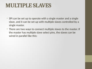
MULTIPLE SLAVES
• SPIcan be set up to operate with a single master and a single
slave, and it can be set up with multiple slaves controlled by a
single master.
• There are two ways to connect multiple slaves to the master. If
the master has multiple slave select pins, the slaves can be
wired in parallel like this:
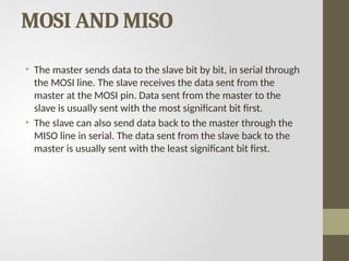
MOSI AND MISO
•The master sends data to the slave bit by bit, in serial through
the MOSI line. The slave receives the data sent from the
master at the MOSI pin. Data sent from the master to the
slave is usually sent with the most significant bit first.
• The slave can also send data back to the master through the
MISO line in serial. The data sent from the slave back to the
master is usually sent with the least significant bit first.
14.
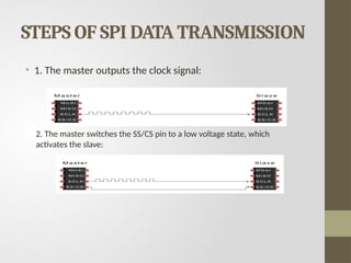
STEPS OF SPIDATA TRANSMISSION
• 1. The master outputs the clock signal:
2. The master switches the SS/CS pin to a low voltage state, which
activates the slave:
15.
Contd..
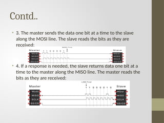
• 3. Themaster sends the data one bit at a time to the slave
along the MOSI line. The slave reads the bits as they are
received:
• 4. If a response is needed, the slave returns data one bit at a
time to the master along the MISO line. The master reads the
bits as they are received:
16.
ADVANTAGES
• No startand stop bits, so the data can be streamed
continuously without interruption
• No complicated slave addressing system like I2C
• Higher data transfer rate than I2C (almost twice as fast)
• Separate MISO and MOSI lines, so data can be sent and
received at the same time
17.
DISADVANTAGES
• Uses fourwires (I2C and UARTs use two)
• No acknowledgement that the data has been successfully
received (I2C has this)
• No form of error checking like the parity bit in UART
• Only allows for a single master


![Communication_Protocols[2][1].pptx on protocoals](https://cdn.slidesharecdn.com/ss_thumbnails/communicationprotocols21-250429164707-38355411-thumbnail.jpg?width=640&height=640&fit=bounds)