Download to read offline

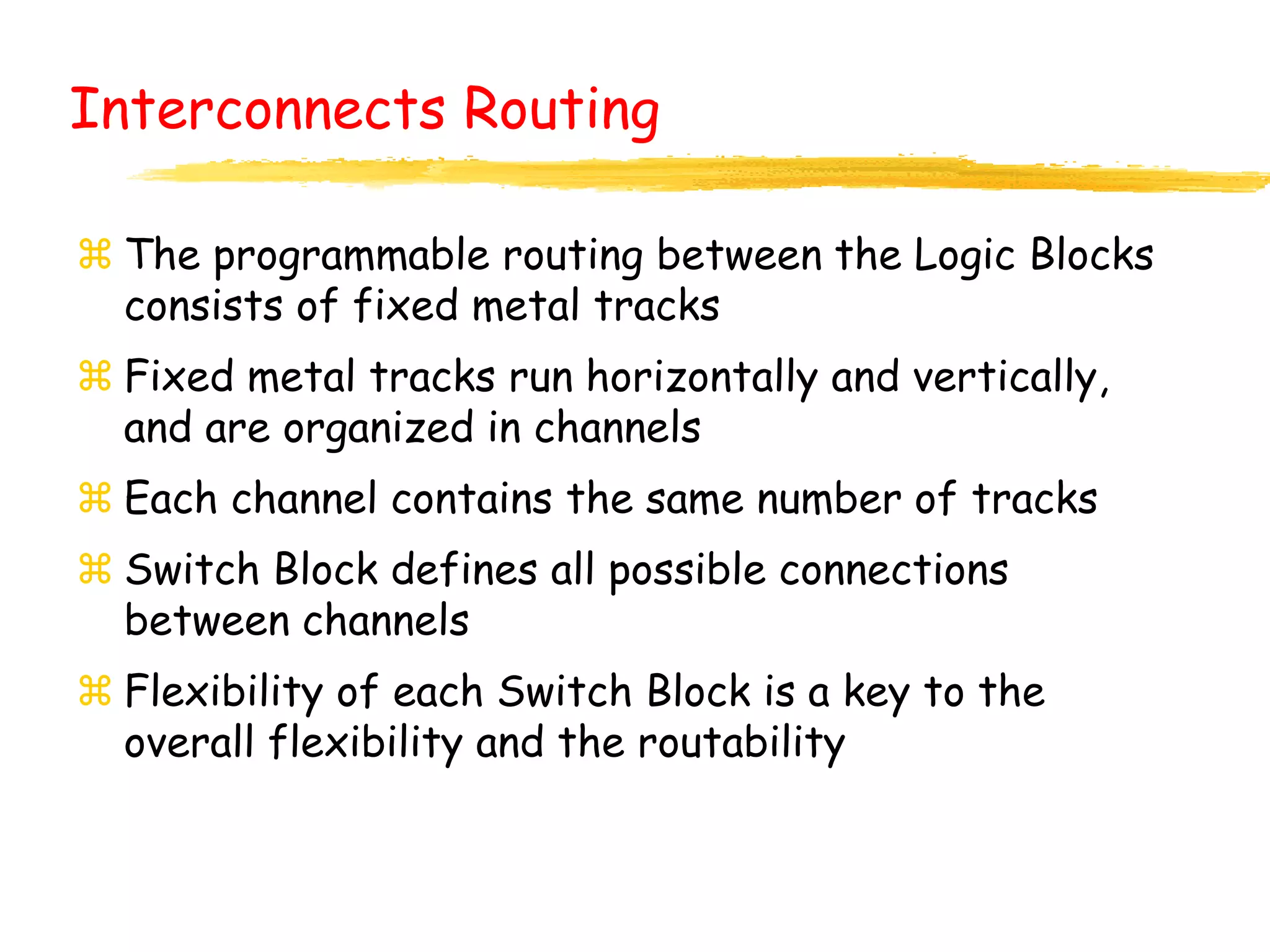
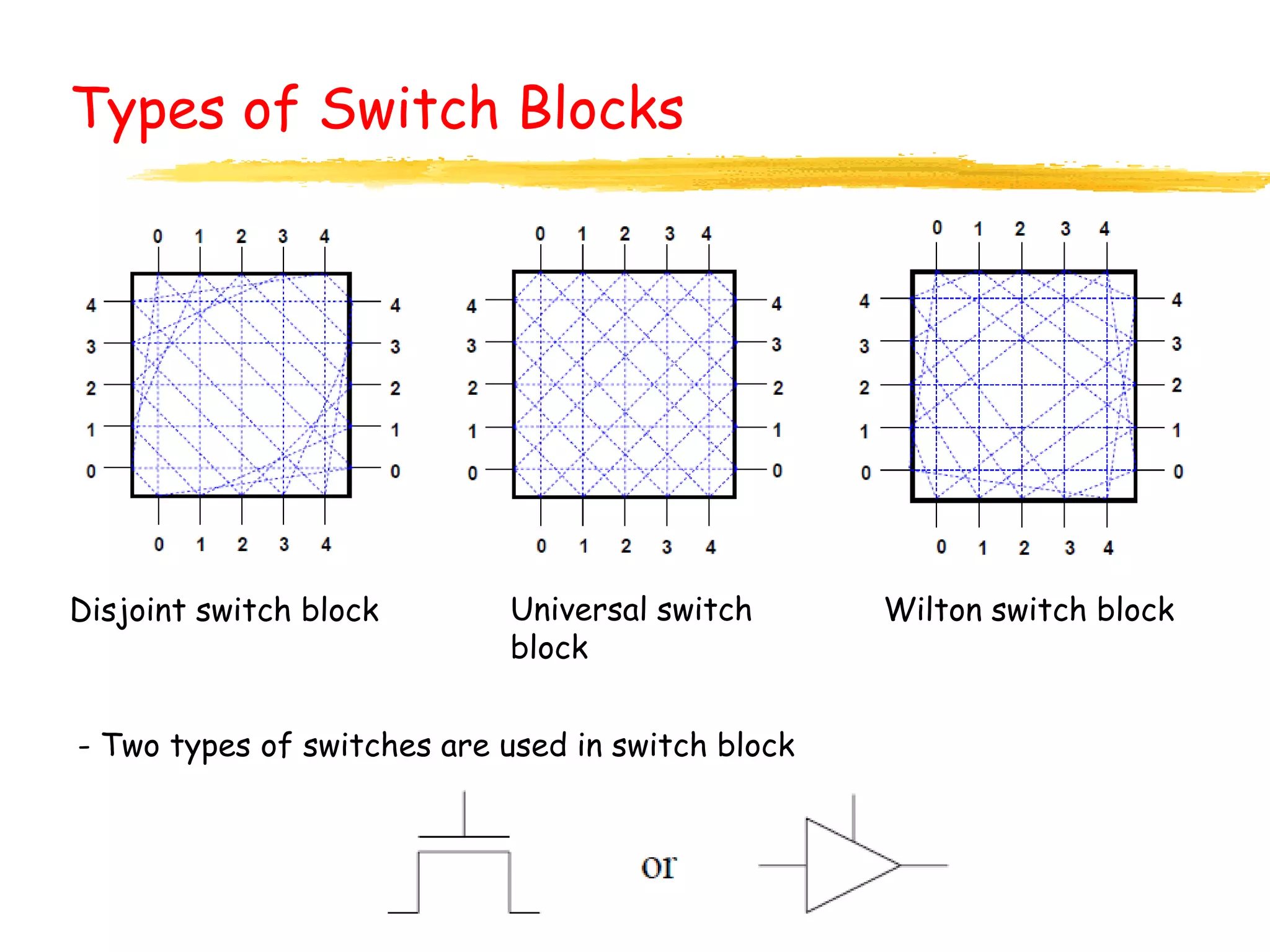
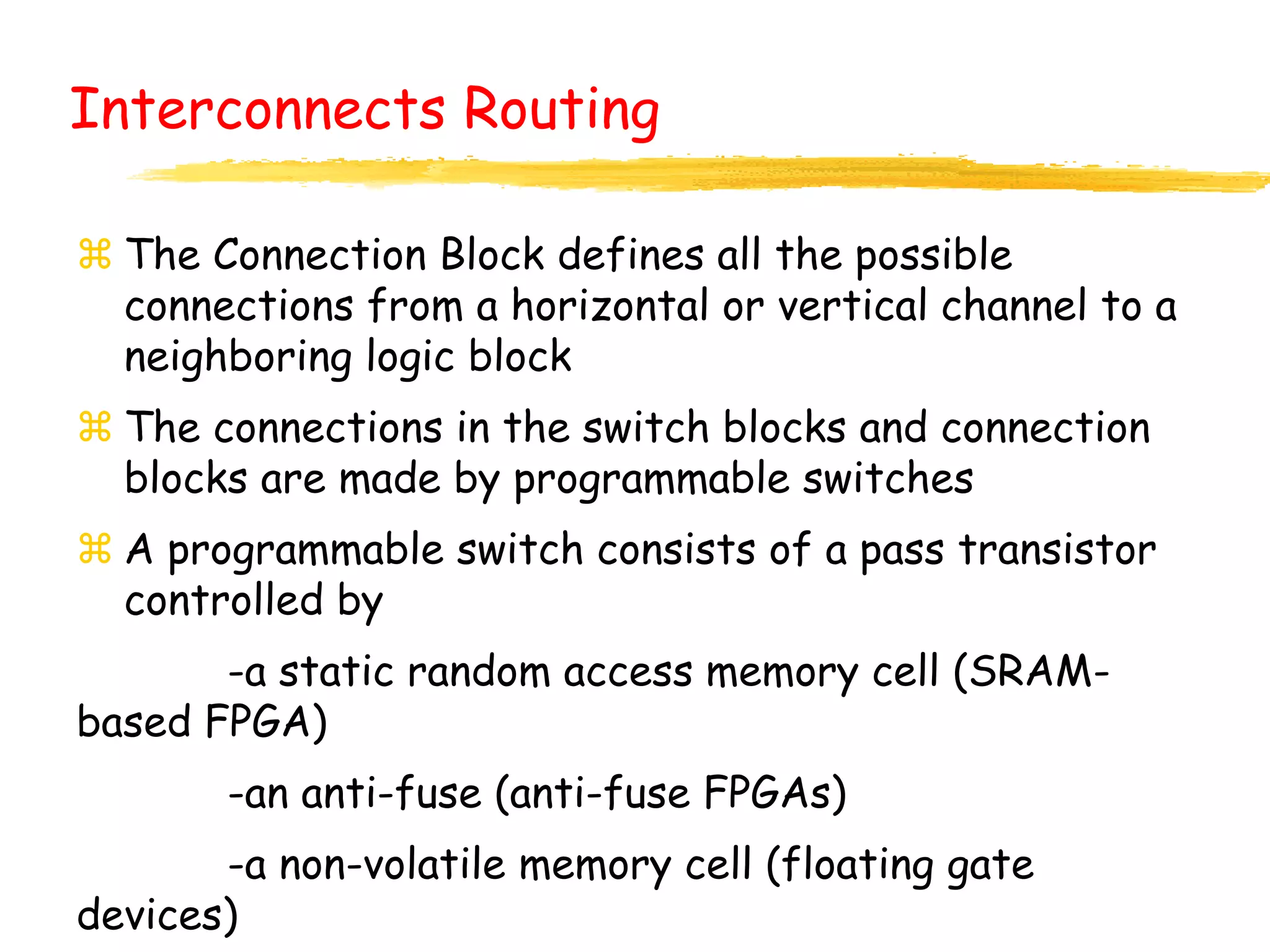

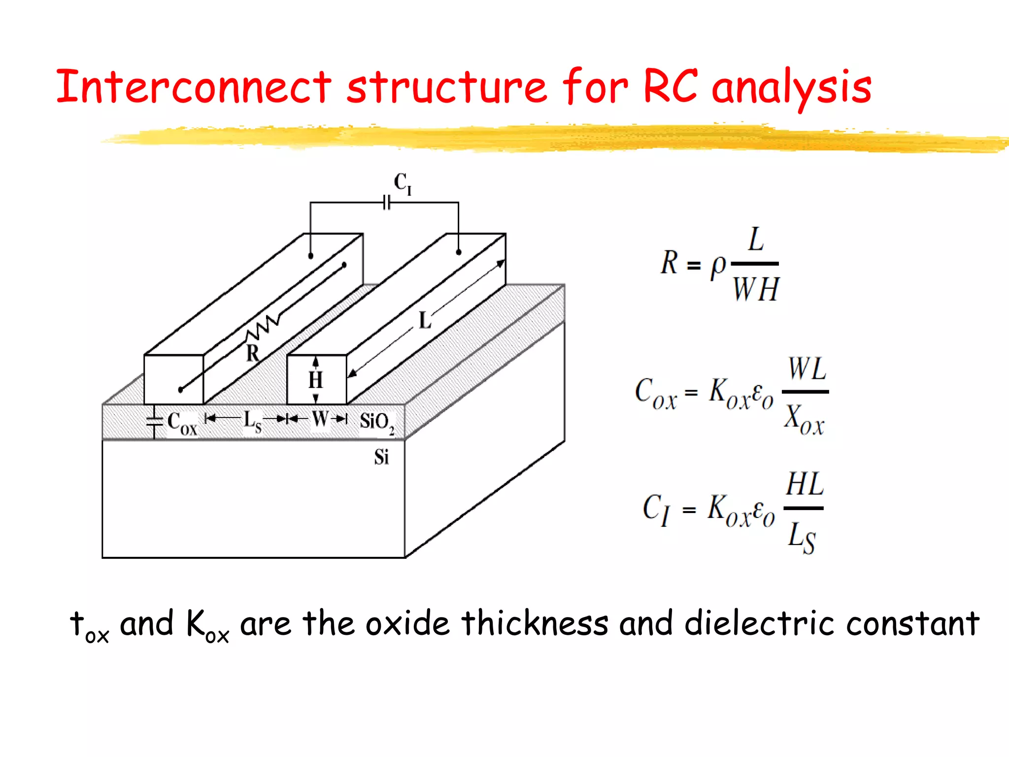
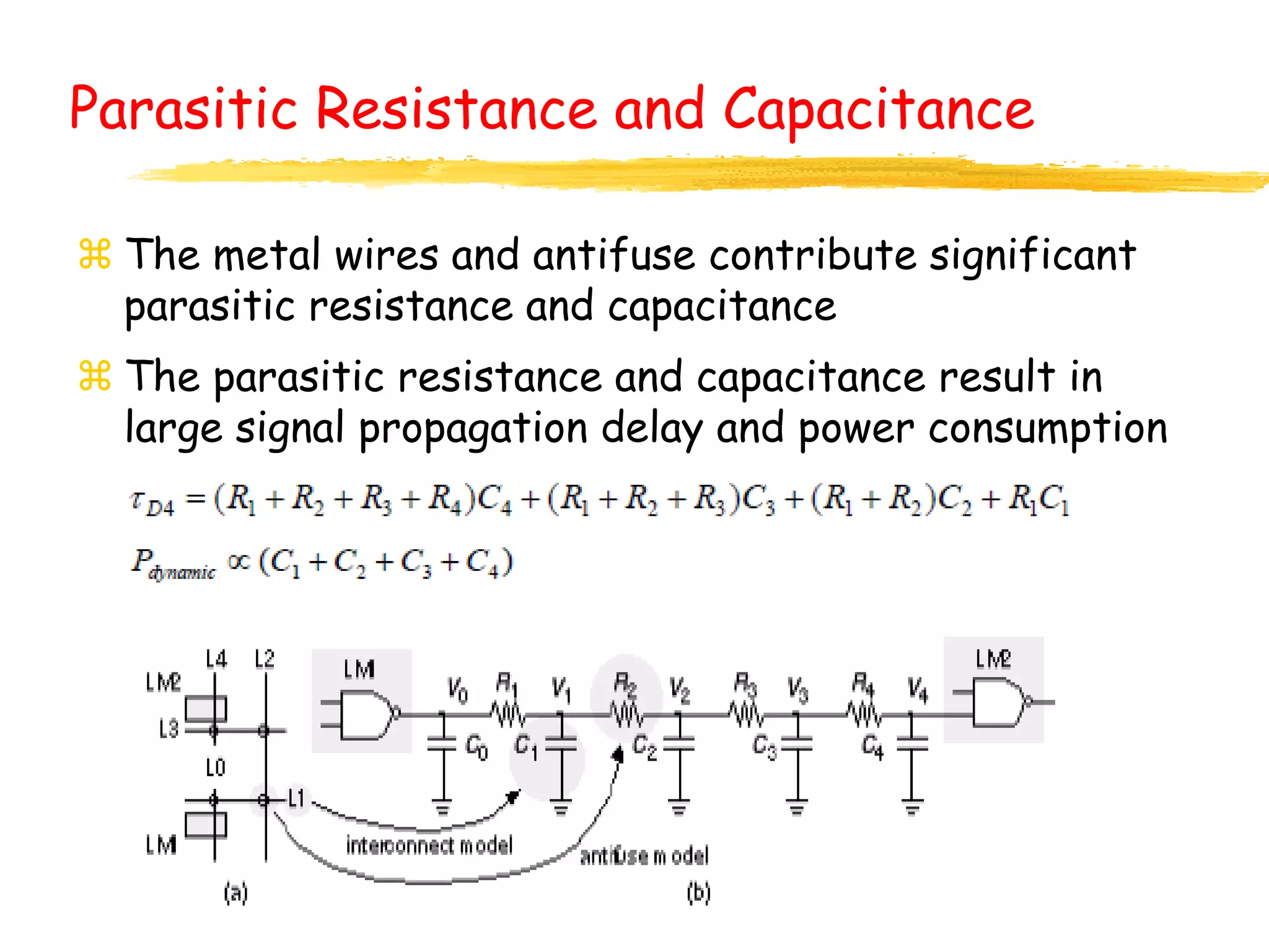
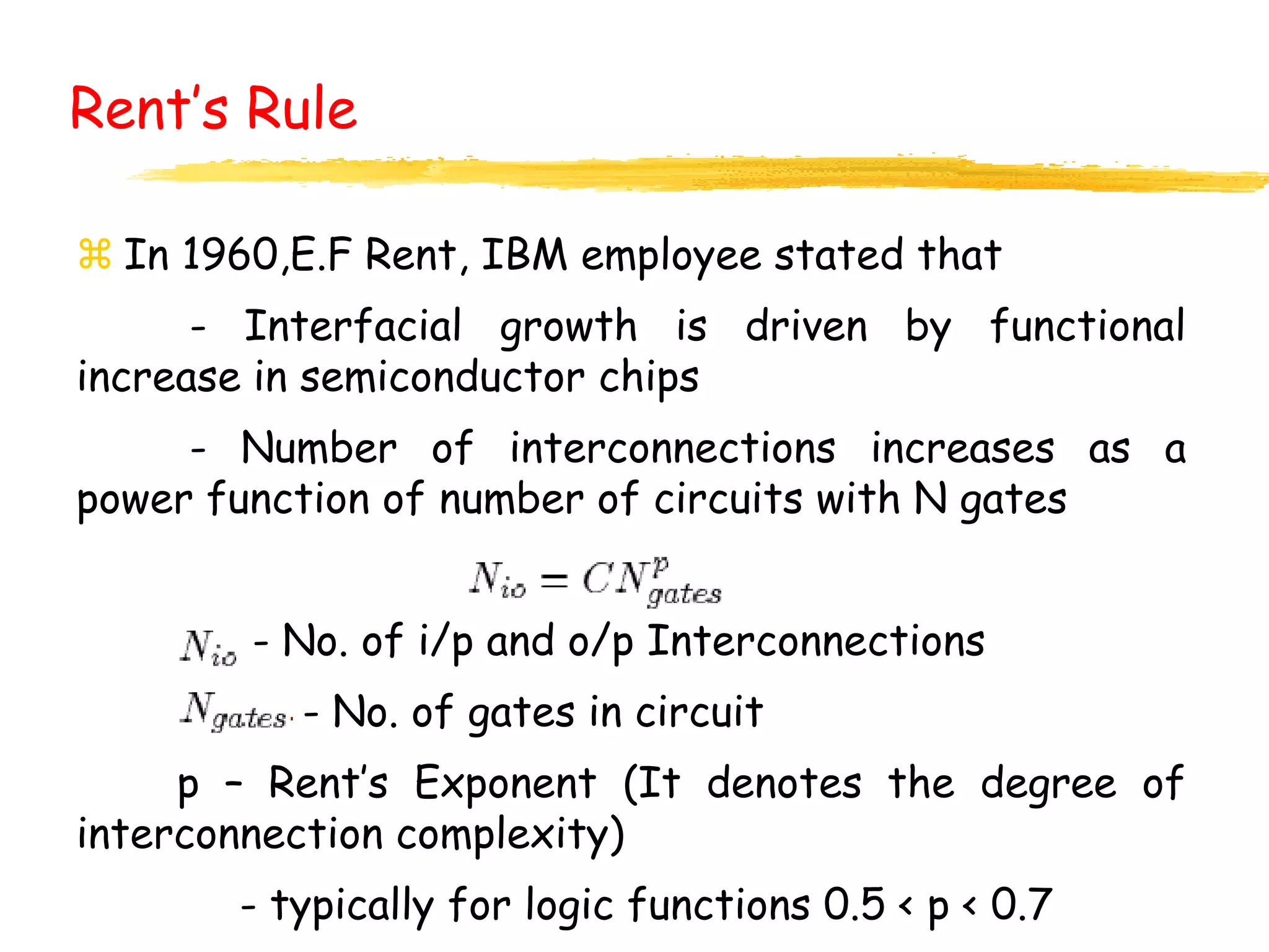
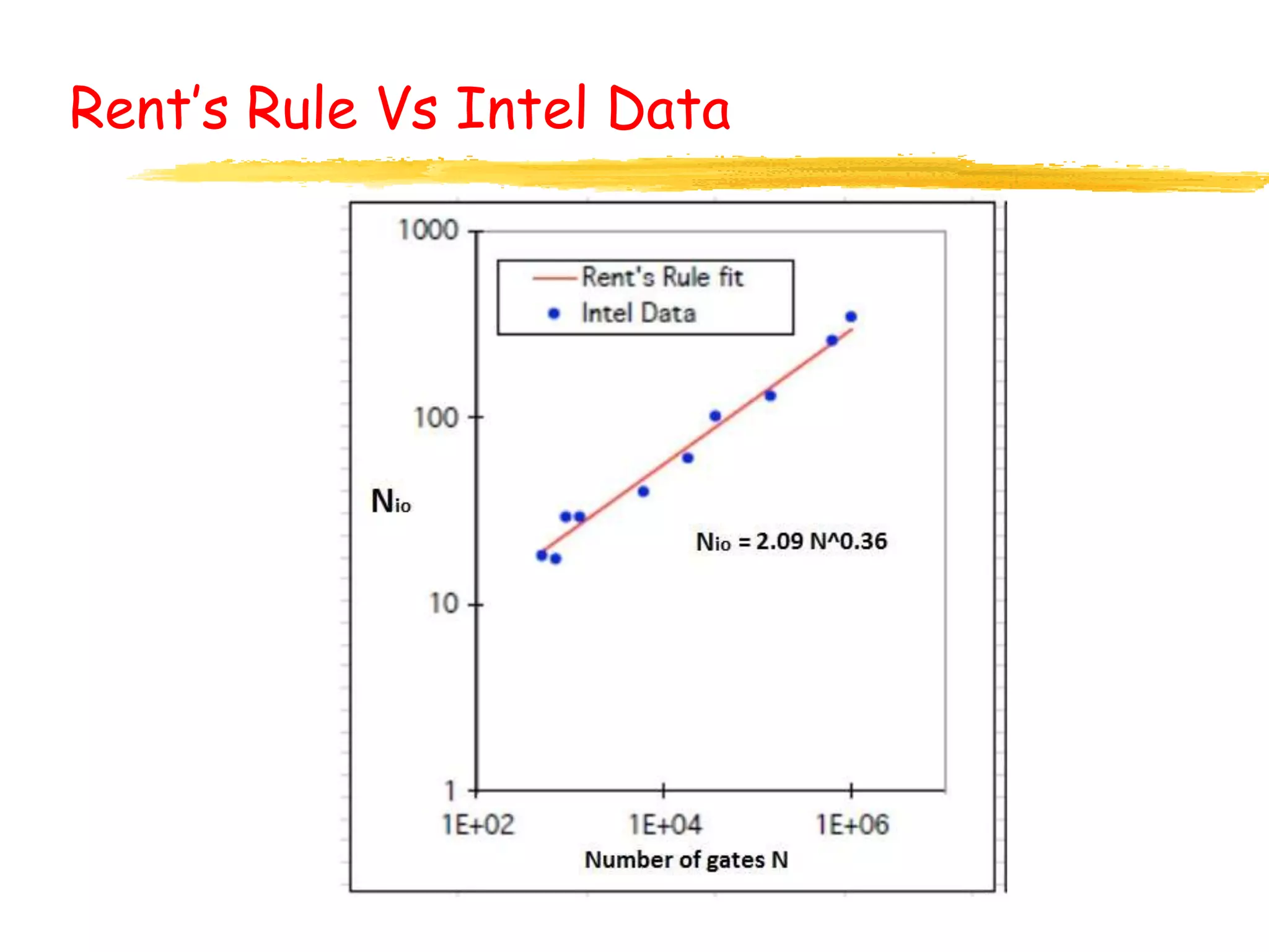


The document discusses the importance and characteristics of interconnects in reconfigurable architectures, specifically in FPGAs. It covers various aspects including area considerations, delay and noise effects, types of interconnects, routing methods, and the implications of Rent’s rule on chip design and performance. The text emphasizes the significant role of interconnects in determining overall functionality and efficiency in semiconductor chips.