The document provides information to calculate the tension required to keep a cylindrical buoy vertical in sea water. Given the buoy's dimensions, mass, and that its center of gravity is 0.9 m from the base, calculations show the buoy is unstable without an upward force. Equating the new buoyancy force from an attached chain to the displaced water volume yields an equation to calculate the necessary tension of 5.639 kN to maintain equilibrium with the buoy vertical.
The document contains examples and solutions for fluid mechanics problems involving pressure, manometers, forces on submerged surfaces, and dams.
1) It calculates gauge and absolute pressures at various depths, pressures for different liquids in manometers, and forces on inclined and triangular planes.
2) It determines beam positions in a dock gate to evenly distribute load, the torque to close a butterfly valve, and the load and point of action on a curved dam face.
The document discusses specific energy, which is the total energy of a channel flow referenced to the channel bed. Specific energy is constant for uniform flow but can increase or decrease for varied flow. Critical flow occurs when specific energy is at a minimum, corresponding to a Froude number of 1. For a rectangular channel, the critical depth formula and specific energy at critical depth are derived. The analysis is also extended to a triangular channel.
Chapter 3 linear wave theory and wave propagationMohsin Siddique
Small amplitude wave theory provides a mathematical description of periodic progressive waves using linear assumptions. It assumes wave amplitude is small compared to wavelength and depth. The key equations derived are the wave dispersion relationship and expressions for water particle velocity, acceleration, and pressure as functions of depth and phase. Wave energy is calculated as the sum of kinetic and potential energy. Wave power is the rate at which wave energy is transmitted shoreward and varies with depth from 0.5 in deep water to 1.0 in shallow water. Wave characteristics like height, length, and celerity change as waves propagate into shallower depths based on conservation of energy.
This document provides information about weirs and Parshall flumes. It discusses different types of weirs including sharp-crested weirs like rectangular and V-notch weirs, as well as broad-crested weirs. Formulas are provided for calculating flow rates over these structures. The document also introduces the Parshall flume, which can be used as an alternative to weirs for measuring flow rates while reducing head losses and sediment accumulation. Key features of the Parshall flume design and measurement principles are described.
Darcy's law describes groundwater flow through porous media such as aquifers. It states that the flow rate of water is proportional to the hydraulic gradient, which is the change in head over the distance of flow. Specifically, the flow rate is equal to the hydraulic conductivity multiplied by the cross-sectional area available for flow and the hydraulic gradient. Darcy's law provides an accurate description of groundwater flow in most environments and conditions. It can be used to estimate flow velocity, flow rate, and travel time of groundwater through aquifers.
Properties of Fluids, Fluid Static, Buoyancy and Dimensional AnalysisSatish Taji
The presentation includes a brief view of the basic properties of a fluid, fluid statics, Pascal's law, hydrostatic law, fluid classification, pressure measurement devices (manometers and mechanical gauges), hydrostatic forces on different surfaces, buoyancy and metacentric height, and dimensional analysis.
The document discusses the direct step method for determining water surface profiles for nonuniform open-channel flow. In nonuniform open-channel flow, the cross-sectional area, depth, and velocity vary along the channel. When the change in fluid depth along the channel dy/dx is much less than one, the flow is classified as gradually varied flow.
1. The document discusses various fluid flow measurement devices and their coefficients, including the coefficient of discharge, coefficient of velocity, and coefficient of contraction.
2. It also covers different flow measurement structures like orifices, weirs, and pitot tubes. It provides the theoretical equations to calculate flow based on these structures.
3. Sample problems at the end demonstrate using the equations to calculate things like flow rate, time to empty a tank, and other flow properties based on given device dimensions and flow conditions.
A broad crested weir with a crest height of 0.3m is located in a channel. With a measured head of 0.6m above the crest, the problem asks to calculate the rate of discharge per unit width, accounting for velocity of approach. Broad crested weirs follow the relationship that discharge per unit width (q) is proportional to the head (H) raised to the power of 3/2. Using this relationship and the given values of 0.3m for crest height and 0.6m for head, the problem is solved through trial and error to find the value of q.
- The document discusses equations for analyzing groundwater flow in confined and unconfined aquifers.
- For confined aquifers, the continuity equation is integrated over the aquifer thickness to derive an equation using transmissivity. Examples are presented of steady horizontal and radial flow.
- For unconfined aquifers, Dupuit assumptions are used and the continuity equation is solved for steady 1D flow using the water table elevation. Worked examples are provided for both confined and unconfined cases.
This document discusses open channel flow and its various types. It defines open channel flow as flow with a free surface driven by gravity. It describes four main types of open channel flows:
1. Steady and unsteady flow
2. Uniform and non-uniform flow
3. Laminar and turbulent flow
4. Sub-critical, critical, and super-critical flow
It also discusses discharge equations for open channels including Chezy's formula, Manning's formula, and Bazin's formula. Finally, it covers specific energy, critical depth, and the hydraulic jump in open channel flow.
Inclining Experiment and Angle of Loll 23 Sept 2019.pptxReallyShivendra
An inclining experiment was conducted to determine a ship's stability, lightship weight, and center of gravity. Weights were moved across the ship in experiments while measuring pendulum deflection. This data was used to calculate the ship's metacentric height (GM) and center of gravity (KG). The angle of loll is the angle at which an unstable ship with negative GM reaches neutral equilibrium and may start to capsize if corrective action is not taken.
This document describes a procedure to determine the bulk density of fine aggregates in a rodded state. The bulk density is measured by filling a cylindrical container one-third at a time with aggregate and tamping it between additions. The container is then weighed filled with aggregate and the bulk density is calculated based on the weight, volume of the container, and weight of the empty container. The results of an example test are presented, finding a bulk density of 1726.20kg/m3 for the given sand sample. The bulk density exceeds the allowable 1600kg/m3 for construction sand.
This document discusses different types of notches and weirs used for measuring flow rates of liquids. It provides formulas to calculate discharge over rectangular, triangular, trapezoidal, broad crested, narrow crested, and submerged/drowned weirs. Key points include: discharge over a triangular notch or weir is given by Q=8/15Cd tan(θ/2)√2gH(5/2); a broad crested weir has a width at least twice the head and discharge is maximized at Qmax=1.705CdL√2gH(3/2); submerged weirs are divided into a free section and drowned section to calculate total discharge.
This document provides an overview of open channel hydraulics. It begins by outlining the key concepts that will be covered, including open channel flow, basic equations like Chezy's and Manning's equations, and the concept of most economical channel sections. The document then defines open channel flow and compares it to pipe flow. It discusses various channel types and flow types in open channels. Empirical formulas for determining coefficients in the open channel flow equations are presented. Examples of applying the Manning's equation to calculate flow rate and velocity are shown. The concept of the most economical channel section is explained for rectangular and trapezoidal channel shapes.
The document outlines a course plan for a foundation engineering course. It includes 9 units that will be covered: introduction and site investigation, earth pressure, shallow foundations, pile foundations, well foundations, slope stability, retaining walls, and soil stabilization. It provides details on the number of lectures for each unit and the topics that will be covered in each lecture. Some key topics include shallow foundation design methods, pile load testing, earth pressure theories, and slope stability analysis techniques. References for the course are also provided.
This document provides an overview and instruction on hydrostatic pressure for students, including defining hydrostatic pressure, discussing pressure measurement devices like manometers, calculating pressure at various points, and providing examples of solving hydrostatic pressure problems. The goal is for students to understand how pressure varies with depth in fluids, be able to use equations to calculate pressure, and describe common pressure measurement tools including piezometers, U-tube manometers, and inclined tube manometers. Practice problems are provided to help students apply the concepts.
This document provides an overview of cables and their analysis. It defines cables as flexible members that can only withstand tension. It lists some common engineering applications of cables. It then outlines the assumptions made in cable analysis, including that cables are flexible, have negligible self-weight, and experience only tension forces. The document explains the procedure for analyzing cables subjected to concentrated loads, including drawing free body diagrams, applying equilibrium equations, and determining tensions and reactions. It provides examples of solving for cable tensions, reactions, slope, and horizontal forces using this procedure.
This document contains 10 examples of calculating seepage and pore water pressure using flow nets. It provides the key steps and calculations for:
1) Determining flow rate, factor of safety against piping, and effective stress at a point.
2) Calculating uplift pressures at multiple points, seepage loss under a dam, and factor of safety against boiling.
3) Estimating how high water would rise in piezometers and seepage loss for a dam.
The document summarizes concepts related to gradually varied flow in open channels. It discusses:
1. The assumptions and equations used in gradually varied flow analysis, including the energy equation.
2. The different types of water surface profiles that can occur depending on factors like bed slope, including mild slope, steep slope, critical slope, horizontal slope, and adverse slope profiles.
3. Methods for computing gradually varied flow profiles, including graphical integration, direct step method for prismatic channels, and standard step method for natural channels.
This document contains summaries of 4 problems involving forces on sluice gates and dams. The first problem is about calculating the magnitude and direction of forces on a semicircular sluice gate that is submerged in water. The second problem involves calculating the resultant force on a curved dam face where the water level is given. The third and fourth problems provide no details about the scenarios but indicate there are additional examples and solutions.
1. The document discusses hydrostatic forces on submerged surfaces including horizontal, vertical, and inclined planes as well as curved surfaces.
2. Key concepts include calculating hydrostatic force based on pressure, depth, and surface area. The center of pressure is also introduced, which is where the total hydrostatic force acts rather than at the geometric centroid.
3. Example problems are provided to calculate hydrostatic forces, center of pressure locations, and buoyancy forces on various submerged objects.
1. Waves are disturbances that transfer energy through a medium, such as water. They can be regular (single frequency/height) or irregular/random (variable frequency/height).
2. Important wave parameters include wavelength, period, frequency, speed, height, amplitude, and water elevation.
3. Ocean waves are classified based on their period/frequency and include capillary, gravity, and infragravity waves.
4. Wind generates waves by transferring energy and momentum to water. Wave characteristics depend on wind speed, fetch (distance over which wind blows), and duration. Fully developed seas occur when energy input balances dissipation.
This document defines key terms and concepts related to ship stability, including Archimedes' principle, center of gravity, center of buoyancy, metacenter, righting arm, and free surface effect. It explains that a ship is stable when its center of buoyancy is below and to the side of the center of gravity, and that the metacenter indicates the ship's stability based on its position relative to the center of gravity. Additionally, it discusses how stability curves illustrate a ship's righting arm at different angles of heel and how the free surface effect can negatively impact stability when compartments are only partially filled with water.
This document contains examples and solutions related to fluid statics concepts such as pressure, density, buoyancy, and Pascal's principle. It begins with examples calculating the mass, weight, density, and pressure using given values. Later examples apply concepts like buoyancy, pressure at depths, and pressure transmission using hydraulic jacks. Key formulas introduced include pressure (p=F/A), fluid pressure (p=hρg), and buoyancy (B=Vfluidρfluid). Overall, the document provides practice problems and solutions for understanding fundamental fluid statics principles.
1) The document presents the solution to calculating the force in a strut connecting two points on a small dam given information about the dam geometry and hydrostatic forces.
2) It also provides examples of calculating forces on structures like gates and stops subjected to hydrostatic forces from water, including determining the minimum volume of concrete needed to balance these forces.
3) The solutions involve applying principles of equilibrium, calculating hydrostatic force components, and summing moments. Analytical expressions for determining forces are developed.
The document is about determining hydrostatic forces on three walls - A, B, and C - holding back water. Wall A is at a 30 degree angle, while walls B and C are at 60 degree angles. Per unit width, wall A requires the greatest resisting moment to counter the hydrostatic force, as the force on wall A is the largest due to its shallower angle and longer length in contact with the water. The hydrostatic force and resisting moment on each wall is calculated using equations for pressure, force, and moments.
This document contains solutions to problems involving the application of Bernoulli's equation to fluid mechanics scenarios. The first problem determines the minimum air pressure required to open a hatch on a structure attached to the ocean floor. The second problem calculates the difference in water depth upstream of a weir under normal and flood flow conditions. The third problem uses Bernoulli's equation to determine the flow rate and vacuum pressure in a siphon system connecting two reservoirs at different elevations.
Ρευστά σε Κίνηση Γ΄ Λυκείου - ΠροβλήματαΒατάτζης .
1. Hydrostatics describes pressure variations in static fluids. Pressure increases with depth due to the weight of the fluid above.
2. The Bernoulli equation relates pressure, velocity, and elevation in fluid flow. It states that the sum of pressure, kinetic energy, and potential energy remains constant along a streamline.
3. Calculations using hydrostatics and the Bernoulli equation allow determining pressures, flows, and forces in applications like pipes, tanks, dams and aircraft wings.
Answers assignment 3 integral methods-fluid mechanicsasghar123456
The document describes calculations related to fluid flow problems involving pipes, nozzles, and turbines. It includes calculations of:
1) Velocity, pressure, density, and mass/volume flow rates at two points in a pipe with gas flow.
2) Pressure change and head loss in a water-filled pipe due to wall shear stress.
3) Initial velocity of ammonia gas flowing from a tank through a pipe, assuming constant vs variable density.
4) Pressure change and jet force from an air flow constricting in a duct.
5) Reaction force of water flowing from a hole in a tank.
6) Flow rate and required turbine diameter to deliver power under different heads.
Velocity distribution, coefficients, pattern of velocity distribution,examples, velocity measurement, derivation of velocity distribution coefficients, problems and solution, Bernoulli's theorem and energy equation, specific energy and equation.
This document contains a 30 question physics exam with multiple choice answers. It covers topics like projectile motion, work, energy, heat, buoyancy, springs, and other concepts in mechanics. The exam was given by Professor Jack Rodriguez during Seminar No. 2 in Physics.
This document contains 20 multiple choice problems related to mechanical engineering. The problems cover topics such as fluid mechanics, thermodynamics, heat transfer, and other mechanical engineering principles. They involve calculations related to things like tank volumes, pressure differences, flow rates, heat transfer between substances, and more. The questions provide relevant equations, known values, and ask the reader to determine unknown values or temperatures based on the given information.
Influences our perception of the world aroundsivaenotes
The document contains 11 multiple choice questions about hydrostatic forces on gates, barriers, tanks, and other structures submerged in water or other fluids. The questions cover topics like calculating horizontal and vertical forces due to fluid pressure, determining minimum mass required to keep a hinged gate closed, and calculating inclination of oil in a tank given an acceleration.
Fox and McDonalds Introduction to Fluid Mechanics 9th Edition Pritchard Solut...KirkMcdowells
Full download : https://alibabadownload.com/product/fox-and-mcdonalds-introduction-to-fluid-mechanics-9th-edition-pritchard-solutions-manual/ Fox and McDonalds Introduction to Fluid Mechanics 9th Edition Pritchard Solutions Manual
1. The document contains 14 problems involving calculation of hydrostatic forces on submerged objects and gates of various shapes. Forces are calculated using principles of pressure variation with depth, center of gravity, buoyancy and taking moments.
2. Problems involve determining total force, location of center of pressure, and reactions at hinges/supports for objects like rectangular/inclined gates, circular gates, cylinders, and dams of different cross-sections immersed in water or other liquids.
3. Additional considerations like fluid density, negative pressure, and imaginary water levels are incorporated based on problem details.
hydraulics and advanced hydraulics solved tutorialsbakhoyaagnes
The document provides solutions to several hydraulic engineering assignments. Assignment 8 asks to find the critical slope and specific energy for a trapezoidal channel given various parameters including a Froude number of 0.12. The solution shows:
1) Using Manning's equation and the given Froude number, relationships are developed between flow rate, depth, and other variables.
2) By iterative solution, the normal flow depth is found to be 0.51m and flow rate 1.132 m3/s.
3) Similarly, the critical depth is found to be 0.125m by setting the Froude number equal to 1.
4) The critical slope is then calculated using the critical flow parameters to
1. The document describes a problem involving the elongation of a tapered bar made of plastic that has a hole drilled through part of its length and is under compressive loads at its ends.
2. It provides the dimensions, material properties, and loads and asks for the maximum diameter of the hole if the shortening of the bar is limited to 8 mm.
3. The solution sets up an equation for the shortening of the bar in terms of the hole diameter and substitutes the given values to solve for the maximum hole diameter of 23.9 mm.
Solution manual for water resources engineering 3rd edition - david a. chinSalehkhanovic
Solution Manual for Water-Resources Engineering - 3rd Edition
Author(s) : David A. Chin
This solution manual include all problems (Chapters 1 to 17) of textbook. in second section of solution manual, Problems answered using mathcad software .
1. Placing a full glass bottle of water in the freezer would cause it to break because water expands as it freezes and the sealed bottle provides no room for expansion.
2. The phase diagram shows that at higher altitudes, the boiling point of water decreases and the melting point increases due to lower atmospheric pressure. This could require longer cooking times in mountains.
3. If two cylinders made of materials A and B conduct heat at the same rate when subjected to the same temperature difference, and the diameter of A is twice the diameter of B, then the thermal conductivity of A is one fourth that of B.
This document discusses the design of open channel sections to convey water flow in the most economical way. It examines rectangular, trapezoidal, triangular, and circular channel cross-sections. For rectangular channels, the most economical section is when the base width is twice the flow depth. For trapezoidal channels, the most economical section is when the side slopes are at an angle of 60 degrees from horizontal and the half top width is equal to the flow depth. Empirical flow equations like Chezy's and Manning's formulas are also presented to estimate normal flow velocities based on hydraulic radius and channel slope.
This document summarizes the design of a reinforced concrete overhead water tank located in Kalyani, West Bengal, India to serve a population of 1500 people. Key aspects of the design include a diameter of 12 meters, total height of 5 meters, capacity of 540000 liters, and a raft foundation. Load calculations and analysis of the dome shape determine that the meridional and hoop stresses are within code limits for the minimum M30 grade concrete. Nominal tensile reinforcement of 6-8mm bars at 180mm centers in both directions is sufficient. Design codes and references used are cited.
Similar to Solved problems in Floating and buyancy.doc (20)
This document provides an overview of various branches of civil engineering including structural engineering, transportation engineering, geotechnical engineering, environmental engineering, construction management, quantity surveying, irrigation engineering, and earthquake engineering. It also discusses related topics like surveying, roads, railways, soil mechanics, fluid mechanics, and the roles of civil engineers in different construction projects. The key branches covered are structural design of buildings and bridges, transportation infrastructure like roads and railways, foundation design and geotechnical soil testing, water and wastewater management, construction planning and management, and disaster mitigation.
This document discusses fluid mechanics and hydraulics concepts including:
1. Definitions of density, specific gravity, atmospheric pressure, absolute and gauge pressure.
2. Descriptions of viscosity, laminar flow, turbulent flow, continuity equation, and steady vs unsteady flow.
3. Explanations of surface tension, capillarity, hydrostatic pressure, buoyancy, and center of pressure.
4. Discussions of manometers, energy equations, forces on submerged surfaces, and fluid static forces.
The document contains 7 practice problems for applying Bernoulli's equation to fluid mechanics situations:
1) Determining the diameter of a jet of water flowing from a tank if the water level remains constant
2) Determining if the water level in a tank with inflows and an outflow weir is rising or falling
3) Calculating pressures and drawing hydraulic grade lines for a pipe system with and without a nozzle
4) Analyzing forces on a vertical gate from upstream water with varying depths
5) Calculating flow rates and pressures at several points in a branched pipeline system
This document provides conversion factors between British gravitational (BG) units and International System of Units (SI) units for various quantities in fluid mechanics and heat transfer. It lists units for length, area, mass, density, force, pressure, temperature, velocity, power, viscosity, volume, and flow rate. For each quantity, it specifies the conversion factor to multiply the BG unit by to obtain the equivalent SI unit. The list of conversion factors is extensive and covers many common units needed for engineering calculations involving fluid properties, forces, heat transfer, and fluid flow behaviors.
Manometers and Pitot tubes are devices used to measure fluid pressure and velocity. A manometer uses a liquid column to measure pressure differences, while a Pitot tube uses a pressure tap to measure flow velocity based on Bernoulli's equation. A manometer can be a simple U-tube or inclined design, while orifices are openings that can be classified by size, shape, and flow characteristics. A Pitot tube has a open end facing flow and static pressure taps, allowing velocity measurement. These devices are essential tools for analyzing fluid systems.
This document contains 5 questions regarding fluid mechanics. Question 1 involves calculating the torque and power required to overcome viscous resistance in a rotating shaft. Question 2 involves calculating pressure drop, head loss, and power required for a given water flow rate through a pipe and orifice system. Question 3 determines the necessary counterweight to balance a water gate. Question 4 calculates the water level in a tank given pump specifications and a triangular weir. Question 5 determines if a hydraulic machine is a pump or turbine and calculates its power output or input.
This document provides information and examples for calculating surface areas and volumes of rectangular and round tanks, as well as clarifier loading calculations. It includes formulas and step-by-step worked examples for determining surface area of rectangles and circles, and volume of rectangular and cylindrical tanks, including those with conical bottoms. Clarifier detention time is defined as the time it takes for water to travel from inlet to outlet.
The document contains questions related to open channel flow, pipe flow, and hydraulic structures. It asks the reader to calculate parameters like normal depth, critical depth, flow depth, head loss, forces on structures, and more for channels, pipes and hydraulic elements based on given flow rates, dimensions, slopes and roughness. The reader is asked to show working and assumptions for multi-part questions involving concepts like specific energy, critical flow, flow transitions, weirs and sluice gates.
The document describes a calculation to determine the height (H) of oil in a rectangular tank at which a hinged gate will just begin to rotate counterclockwise. The gate is subjected to an upward force from the oil (F1) and a leftward force from the air pressure (F2). F1 is calculated based on the oil density, area of the gate, and height of the oil column. F2 is given as the air pressure times the gate area. Setting F1 equal to F2 and solving for H gives the critical height at which rotation will occur.
The document discusses several fluid mechanics problems involving pipes, valves, pumps, and Venturi meters. It provides the relevant equations, diagrams, and step-by-step workings to calculate pressure, velocity, discharge, and other flow parameters for each problem.
The document also contains an Arabic passage discussing philosophical concepts like thinking outside the box and challenging preconceived notions.
The document contains questions related to open channel flow, pipe flow, and hydraulic structures. It asks the reader to calculate parameters like normal depth, critical depth, flow depth, head loss, force on structures, and more for channels, pipes and hydraulic elements based on given cross-sections, slopes, roughness and discharge. It also contains multiple choice questions testing understanding of concepts like Darcy-Weisbach equation, Chezy's formula, relationship between EGL, HGL and velocity head.
The document appears to be a 14-page final exam for a Hydraulic I course taught by Dr. Ezzat El-sayed G. SALEH in January 2017. It contains multiple pages of questions related to hydraulics for students taking the CVE 215 Hydraulic I course final.
The document contains lecture notes on hydraulics from Minia University in Egypt. It defines key terms related to fluid mechanics such as density, viscosity, laminar and turbulent flow, compressibility, and surface tension. It also provides the continuity equation and defines different types of fluid flow such as steady, uniform, rotational, and one, two, and three-dimensional flow. The notes conclude by listing the Bernoulli equation and its assumptions.
The document is a study sheet on Bernoulli's equation and its applications. It contains 7 practice problems applying Bernoulli's equation to calculate things like water flow rates, pressures at different points, and forces on gates. Diagrams illustrate the hydraulic systems and students are asked to calculate values, sketch graphs, and determine if water levels are rising or falling. The problems involve nozzles, pipes, weirs, and cylinders to demonstrate applications of Bernoulli's equation in hydraulics.
This document provides an overview of various topics in civil engineering, including the different branches and their applications. It discusses surveying, structural engineering, transportation engineering, geotechnical engineering, construction management, irrigation engineering, earthquake engineering, and the roles of civil engineers in construction projects like buildings and dams. The key information presented includes the different types of structures, loads, soils, roads, and the purposes and methods of each civil engineering specialty.
This document discusses Pelton wheel turbines. It begins with an overview of Pelton wheels and their components. It then provides explanations of key concepts such as impulse turbines, velocity diagrams, effective head, maximum power output, and hydraulic efficiency. Practical considerations for Pelton wheel design like optimal bucket angles are also covered. Finally, it discusses turbine selection and the typical range of specific speeds for different turbine types.
This document defines and describes different types of fluid flows. It discusses ideal and real fluids, Newtonian and non-Newtonian fluids, laminar and turbulent flow, steady and unsteady flow, uniform and non-uniform flow, compressible and incompressible flow, rotational and irrotational flow, and viscous and non-viscous flow. Key fluid properties like viscosity, density, and compressibility are covered. Examples are provided to illustrate different fluid types and flows.
This document contains diagrams and questions related to fluid mechanics:
1) It shows diagrams of different devices moving in fluid and asks whether each will move in the positive or negative x-direction assuming equal pressure at the entrance and exit.
2) It shows a diagram of a sprinkler and asks to determine the torque required to prevent its rotation given the fluid velocity and distance from the point of rotation.
3) It shows a diagram of a vane moving through fluid and asks to determine the force on the vane given its angle, velocity through the fluid, and the fluid velocity striking it.
4) It asks which factors the pressure at the summit of a siphon depends on out of liquid density
The document discusses hydraulic grade lines (HGL) and energy grade lines (EGL), which are tools for representing energy in hydraulic systems. It notes that three key equations - discharge and continuity, energy, and momentum - are fundamental to solving most hydrodynamic problems. HGLs and EGLs provide a visual representation of energy along a flow path to help identify points of concern in design and analysis. Examples are given of how HGLs and EGLs change with factors like pipe diameter, valves, nozzles, pumps, and turbines.
Comparative analysis between traditional aquaponics and reconstructed aquapon...bijceesjournal
The aquaponic system of planting is a method that does not require soil usage. It is a method that only needs water, fish, lava rocks (a substitute for soil), and plants. Aquaponic systems are sustainable and environmentally friendly. Its use not only helps to plant in small spaces but also helps reduce artificial chemical use and minimizes excess water use, as aquaponics consumes 90% less water than soil-based gardening. The study applied a descriptive and experimental design to assess and compare conventional and reconstructed aquaponic methods for reproducing tomatoes. The researchers created an observation checklist to determine the significant factors of the study. The study aims to determine the significant difference between traditional aquaponics and reconstructed aquaponics systems propagating tomatoes in terms of height, weight, girth, and number of fruits. The reconstructed aquaponics system’s higher growth yield results in a much more nourished crop than the traditional aquaponics system. It is superior in its number of fruits, height, weight, and girth measurement. Moreover, the reconstructed aquaponics system is proven to eliminate all the hindrances present in the traditional aquaponics system, which are overcrowding of fish, algae growth, pest problems, contaminated water, and dead fish.
CHINA’S GEO-ECONOMIC OUTREACH IN CENTRAL ASIAN COUNTRIES AND FUTURE PROSPECTjpsjournal1
The rivalry between prominent international actors for dominance over Central Asia's hydrocarbon
reserves and the ancient silk trade route, along with China's diplomatic endeavours in the area, has been
referred to as the "New Great Game." This research centres on the power struggle, considering
geopolitical, geostrategic, and geoeconomic variables. Topics including trade, political hegemony, oil
politics, and conventional and nontraditional security are all explored and explained by the researcher.
Using Mackinder's Heartland, Spykman Rimland, and Hegemonic Stability theories, examines China's role
in Central Asia. This study adheres to the empirical epistemological method and has taken care of
objectivity. This study analyze primary and secondary research documents critically to elaborate role of
china’s geo economic outreach in central Asian countries and its future prospect. China is thriving in trade,
pipeline politics, and winning states, according to this study, thanks to important instruments like the
Shanghai Cooperation Organisation and the Belt and Road Economic Initiative. According to this study,
China is seeing significant success in commerce, pipeline politics, and gaining influence on other
governments. This success may be attributed to the effective utilisation of key tools such as the Shanghai
Cooperation Organisation and the Belt and Road Economic Initiative.
Advanced control scheme of doubly fed induction generator for wind turbine us...IJECEIAES
This paper describes a speed control device for generating electrical energy on an electricity network based on the doubly fed induction generator (DFIG) used for wind power conversion systems. At first, a double-fed induction generator model was constructed. A control law is formulated to govern the flow of energy between the stator of a DFIG and the energy network using three types of controllers: proportional integral (PI), sliding mode controller (SMC) and second order sliding mode controller (SOSMC). Their different results in terms of power reference tracking, reaction to unexpected speed fluctuations, sensitivity to perturbations, and resilience against machine parameter alterations are compared. MATLAB/Simulink was used to conduct the simulations for the preceding study. Multiple simulations have shown very satisfying results, and the investigations demonstrate the efficacy and power-enhancing capabilities of the suggested control system.
Harnessing WebAssembly for Real-time Stateless Streaming PipelinesChristina Lin
Traditionally, dealing with real-time data pipelines has involved significant overhead, even for straightforward tasks like data transformation or masking. However, in this talk, we’ll venture into the dynamic realm of WebAssembly (WASM) and discover how it can revolutionize the creation of stateless streaming pipelines within a Kafka (Redpanda) broker. These pipelines are adept at managing low-latency, high-data-volume scenarios.
International Conference on NLP, Artificial Intelligence, Machine Learning an...gerogepatton
International Conference on NLP, Artificial Intelligence, Machine Learning and Applications (NLAIM 2024) offers a premier global platform for exchanging insights and findings in the theory, methodology, and applications of NLP, Artificial Intelligence, Machine Learning, and their applications. The conference seeks substantial contributions across all key domains of NLP, Artificial Intelligence, Machine Learning, and their practical applications, aiming to foster both theoretical advancements and real-world implementations. With a focus on facilitating collaboration between researchers and practitioners from academia and industry, the conference serves as a nexus for sharing the latest developments in the field.
Batteries -Introduction – Types of Batteries – discharging and charging of battery - characteristics of battery –battery rating- various tests on battery- – Primary battery: silver button cell- Secondary battery :Ni-Cd battery-modern battery: lithium ion battery-maintenance of batteries-choices of batteries for electric vehicle applications.
Fuel Cells: Introduction- importance and classification of fuel cells - description, principle, components, applications of fuel cells: H2-O2 fuel cell, alkaline fuel cell, molten carbonate fuel cell and direct methanol fuel cells.
ACEP Magazine edition 4th launched on 05.06.2024Rahul
This document provides information about the third edition of the magazine "Sthapatya" published by the Association of Civil Engineers (Practicing) Aurangabad. It includes messages from current and past presidents of ACEP, memories and photos from past ACEP events, information on life time achievement awards given by ACEP, and a technical article on concrete maintenance, repairs and strengthening. The document highlights activities of ACEP and provides a technical educational article for members.
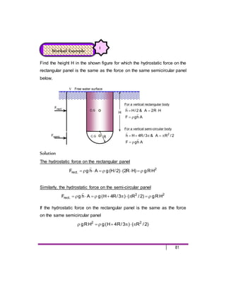
1. 81
Find the height H in the shown figure for which the hydrostatic force on the
rectangular panel is the same as the force on the same semicircular panel
below.
H
R
C.G
C.G
Frect
Fsemi.
A
h
g
F
H
R
2
A
&
2
/
H
h
For a vertical rectangular body
For a vertical semi-circular body
A
h
g
F
2
/
R
A
&
3
/
R
4
H
h 2
Free water surface
Solution
The hydrostatic force on the rectangular panel
2
.
rect H
R
g
)
H
R
2
(
)
2
/
H
(
g
A
h
g
F
Similarly, the hydrostatic force on the semi-circular panel
2
2
.
rect H
R
g
)
2
/
R
(
)
3
/
R
4
H
(
g
A
h
g
F
If the hydrostatic force on the rectangular panel is the same as the force
on the same semicircular panel
)
2
/
R
(
)
3
/
R
4
H
(
g
H
R
g 2
2
Worked Example
1
2. 82
Canceling g
from both sides and rearranging gives
0
3
/
2
)
R
/
H
(
2
)
R
/
H
( 2
Solving for H/R gives
2
)
3
/
2
(
4
)
2
/
(
2
/
R
H
2
or
R
1.918
3
/
2
4
/
4
/
R
H 2
A steel pipeline conveying gas has an internal diameter of 120 cm and an
external diameter if 125 cm. It is laid across the bed of a river, completely
immersed in water and is anchored at intervals of 3 m along its length.
Calculate the buoyancy force in Newton per meter and the upward
force in Newton on each anchorage. Density of steel = 7900 kg/m3
,
density of water = 1000 kg/m3
.
Solution
Worked Example
2
3. 83
Upward Force
W
FB
D
i
n
=
1
2
0
c
m
t = 2.5 cm
Steel gas pipeline of S.G = 7.9
Waterline
3.0 m CL to CL
The buoyancy force in Newton per meter, (the pipe is completely
immersed in water)
m
/
kN
033
.
12
0
.
1
4
25
.
1
81
.
9
1000
)
olume
displacedv
(
g
F
2
water
B
Weight of the steel pipe =
m
/
kN
456
.
7
0
.
1
4
)
20
.
1
25
.
1
(
81
.
9
7900
)
Volume
(
g
2
2
steel
The upward force on each anchorage =
m
/
kN
731
.
13
3
)
456
.
7
033
.
12
(
3
)
W
F
( B
(The pipe is anchored at intervals of 3 m along its length)
4. 84
A vessel lying in a fresh-water dock has a displacement of 10 000 tones
and the area of the water-line plane is 1840 m2
. It is moved to a sea-water
dock and after removal of cargo its displacement is reduced to 8 500
tones. Assuming that the sides of the vessel are vertical near the waterline
and taking the density of the fresh water as 1000 kg/m3
and that of sea
water as 1025 kg/m3,
Calculate the alternation in draft?
Solution
Case A: when the vessel is lying in a fresh-water dock
For equilibrium,
)
d
Area
(
g
displaced
volume
g
F
W B
or
)
Area
(
g
F
W
d B
Thus, for a fresh displacement water of 10 000 tones and the area of the
water-line plane is 1840 m2
The draft ”d” fresh water =
2
3
B
m
435
.
5
1840
81
.
9
1000
81
.
9
10
000
10
Area
g
W
F
Case B: when the vessel is lying in a sea-water dock
Worked Example
3
5. 85
For a displacement of sea-water of 8 500 tones and the same area of the
water-line plane of 1840 m2
The draft ”d” sea water =
2
3
B
m
507
.
4
1840
81
.
9
1025
81
.
9
10
500
8
Area
g
W
F
The alternation in draft = ”d” fresh water - ”d” sea water
= 5.435 – 4.507 = 0.928 m
A rectangular pontoon 10.5 m long, 7.2 m board and 2.4 m deep has a
mass of 70 000 kg. It carries on its upper deck a horizontal boiler of 4.8 m
diameter and a mass of 50 000 kg. The center of gravity of the boiler and
the pontoon may be assumed to be at their centers of figure and in the
same vertical line.
Find the metacentric height (Density of sea water 1025 kg/m3
).
Solution
The effective center of gravity of the pontoon and the boiler can be
calculated by taking the moment about point “O” at the bottom,
Worked Example
4
6. 86
m
70
.
2
)
000
50
000
70
(
)
4
.
2
4
.
2
(
000
50
2
.
1
000
70
OG
CL
d / 2 = 0.77
Sea water of
S.G=1.025
d
O
B
G
M
2.4 m
4.80
m
Waterline
M
G
B
O
2.79
2.70
7.2 m
W = 70 000 kg
W’= 50 000 kg
For equilibrium, B
F
W
Thus,
The displaced volume of water = 2
B
m
07
.
117
81
.
9
1025
000
120
g
W
F
The draft, d = m
55
.
1
2
.
7
5
.
10
07
.
117
pontoon
the
of
Area
V
and
The height of center of buoyancy above the bottom OB =
m
775
.
0
2
/
55
.
1
2
/
d
The distance m
79
.
2
07
.
117
)
12
/
2
.
7
5
.
10
(
V
I
BM
3
7. 87
The metacentric height, GM
m
865
.
0
)
775
.
0
70
.
2
(
79
.
2
BG
BM
GM
A rectangular pontoon 10m by 4m in plane weights 280kN is placed
longitudinally on the deck. A steel tube weighting 34 kN is in a central
position, the center of gravity for the combined weight lies on the vertical
axis of symmetry 250mm above the water surface. Find:
The metacentric height,
The maximum distance the tube may be rolled laterally across the
deck if the angle of heel is not to exceed 5o
.
Solution
W’ = 34 KN
water of S.G =1.0
d
O
B
G
M
Overturning
Moment = W’. X
0.025 m
X
Worked Example
5
8. 88
Total weight of the pontoon and the steel tube= 280 + 34 = 314 KN
For equilibrium,
B
F
W
Thus,
The displaced volume of water = 3
3
B
m
32
81
.
9
1000
10
314
g
W
F
The draft, d = m
80
.
0
4
10
32
pontoon
the
of
Area
V
and
The height of center of buoyancy above the bottom OB =
m
40
.
0
2
/
80
.
0
2
/
d
The distance m
67
.
1
32
)
12
/
4
10
(
V
I
BM
3
The metacentric height, GM
m
02
.
1
)
40
.
0
25
.
0
(
67
.
1
BG
BM
GM
When the tube may be rolled laterally across the deck it causes
the pontoon to heel through an angle (the angle of heel is not to
exceed 5o
).For equilibrium in the heeled position, the righting
moment must equal the overturning moment
MG
W
X
W'
or )
180
/
5
(
02
.
1
314
X
34
from which X = 0.822 m
9. 89
The maximum distance the tube may be rolled laterally across
the deck if the angle of heel is not to exceed 5o
0.822m
A cylindrical buoy 1.35 m in diameter 1.8 m high has a mass of 770 kg.
The metacentric height,
Show that it will not float with its axis vertical in sea water of
density 1025 kg/m.
If one end of a vertical chain is fasten to the base, find the pull
required to keep the buoy vertical. The center of gravity of the
buoy is 0.9 m from its base.
Solution
Worked Example
6
1.80 m
1.35 m
d
O
B
G
O
B
G
M
d /2
h/2
water of S.G =1.025
10. 90
For equilibrium,
B
F
W
Thus,
The displaced volume of water = 2
B
m
751
.
0
81
.
9
1025
81
.
9
770
g
W
F
The draft, d = m
524
.
0
4
/
3
.
1
751
.
0
pontoon
the
of
Area
V
2
and
The height of center of buoyancy above the bottom OB =
m
262
.
0
2
/
524
.
0
2
/
d
The distance
m
217
.
0
524
.
0
16
35
.
1
d
16
D
d
)
4
/
D
(
)
64
/
D
(
V
I
BM
2
2
2
4
The metacentric height, GM
m
421
.
0
)
262
.
0
90
.
0
(
217
.
0
BG
BM
GM
Negative metacentric height indicates that the buoy is unstable
If one end of a vertical chain is fasten to the base; and “T” = tension in
the chain in Newtowns,
New buoyancy force
W
T
F'
B
11. 91
New displacement volume
3
'
B
'
B
m
81
.
9
1025
F
g
F
New draft
m
393
14
F
)
4
/
35
.
1
(
81
.
9
1025
F
)
Area
(
g
F '
B
2
'
B
'
B
New height of buoyancy above “O”
m
786
28
F
393
14
F
5
.
0
'
B
'
B
m
F
5
.
639
1
)
393
14
/
F
(
16
35
.
1
d
16
D
d
)
4
/
D
(
)
64
/
D
(
V
I
BM '
B
'
B
2
2
2
4
'
B
'
B
F
5
.
639
1
786
28
F
90
.
0
OM
OG
G
M
and
m
90
.
0
OG
1.80 m
d
O
B
G
O
B
G
M
d/2
h/2
T
w
M
FB
12. 92
For equilibrium; taking the moment about G gives,
'
B
'
B
'
B
'
B
F
5
.
639
1
786
28
F
90
.
0
F
BG
F
90
.
0
T
or
'
B
'
B
'
B
'
B
'
B
F
5
.
639
1
786
28
F
90
.
0
F
BG
F
)
W
F
(
90
.
0
Solving for '
B
F gives,
N
632
4
81
.
9
770
12186
T
and
N
12186
F'
B
Consider a homogeneous right circular cylinder of height h, radius R, and
specific gravity SG, floating in water (SG = 1.0).
Show that the body will be stable with its axis vertical if
)
SG
1
(
SG
2
h
R
Solution
Assume that the cylinder has a length L, radius R, specific gravity S.G and
floats stable in water with a draft d. Therefore, the water line area relative
to tilt axis = R2
. Meanwhile,
Worked Example
7
13. 93
The distance
d
4
R
d
R
4
/
R
V
I
BM
2
2
4
…….. (1)
To find the relation between h (height of the cylinder) and the draft d, for
equilibrium it follows that,
B
F
W
or
d
R
g
G
.
S
h
R
g
G
.
S 2
2
h
G
.
S
d
…….. (2)
and
2
/
d
OB
&
2
/
h
OG
h
D
=
2R
d
O
B
G
O
B
G& M
d /2
h/2
water of S.G =1.0
Cylinder of of S.G
The metacentric height MG is positive,
i.e. The distance, )
d
h
(
5
.
0
OG
OB
BG
MG
………….... (3)
S.G = 1.0
14. 94
Substituting Eq. (2) into Eq. (3) gives
)
G
.
S
1
(
2
h
BG
…….. (4)
For stability the metacentric height GM = BM – BG must be positive, so
that BM must be greater than GM or,
From Eq. (1) and Eq. (4)
)
SG
1
(
2
h
h
G
.
S
4
R2
or
)
SG
1
(
G
.
S
2
h
R
A hollow wooden cylinder of S.G 0.55 has an outer diameter of 0.60 m, an
inner diameter of 0.30 m and has its ends open. It is required to float in oil
of S.G 0.84
Calculate the maximum height of the cylinder so that it shall be
stable when floating with its axis vertical and the depth to which it
will sink.
Solution
Worked Example
8
15. 95
The distance
d
16
)
D
D
(
4
/
)
D
D
(
d
64
/
)
D
D
(
V
I
BM
2
in
2
out
2
in
2
out
4
in
4
out
d
16
45
.
0
d
16
30
.
0
60
.
0
BM
2
2
…….. (1)
The distance, BG = OB – OG = )
d
h
(
5
.
0
…….. (2)
To find the relation between h (height of the cylinder) and the draft d,
For equilibrium,
B
F
W
or
d
4
/
)
D
D
(
g
h
4
/
)
D
D
(
g 2
in
2
out
oil
2
in
2
out
wood
d
527
.
1
d
h
wood
oil
…….. (3)
Eq. (2) and (3) gives
d
264
.
0
)
0
.
1
527
.
1
(
d
5
.
0
BG
…….. (4)
For stability the metacentric height GM = BM – BG must be positive, so
that BM must be greater than GM or,
From Eq. (1) and Eq. (4)
d
264
.
0
d
16
45
.
0
16. 96
h
d
O
B
M &G
S. G = 0.84
S. G = 0.55
0.60 m
0.15 m
Neutral equilibrium
The depth to which the cylinder will sink m
327
.
0
d and,
The maximum height of the cylinder so that it shall be stable when
floating with its axis vertical
m
50
.
0
327
.
0
527
.
1
d
527
.
1
h
A pontoon is to be used as a working platform for diving activities
associated with a dockyard scheme. The pontoon is to be rectangular in
both plane and elevation, and is to have the following specification:
Width = 6.0 m,
Mass = 300 000 kg,
Metacentric height 1.50 m,
Worked Example
9
17. 97
The pontoon center of gravity = 0.30 m above geometrical center,
Freeboard (height from water level to deck) 750 mm.
Estimate: The overall length, L, and the overall height, h for the
pontoon if it is floating in fresh water (density = 1000 kg/m3
)
Solution
The given specifications:
The center of buoyancy, B, is at the center of gravity of the
displaced water = 2
/
d
OB
The pontoon center of gravity = 0.30 m above geometrical center.
i.e.
m
30
.
0
2
/
h
OG
and )
m
(
75
.
0
d
h
at least
m
675
.
0
30
.
0
)
d
75
.
0
d
(
5
.
0
30
.
0
)
d
h
(
5
.
0
BG
m
175
.
2
50
.
1
675
.
0
GM
BG
BM
…………………….… (1)
The volume of water displaced =
Mass / = 300 000 / 1000 = 300 m2
and
L
18
12
/
6
L
12
/
B
L
I 3
3
The distance L
06
.
0
300
L
18
V
/
I
BM
…………… (2)
18. 98
6.0 m
d
Freeboard
0.75 m
B
G
O
L
=
?
?
h
=
?
?
M
Metacentric height = 1. 50 m
Mass =
300 000 kg
S.G. = 1.0
CL
CL
From Eq. (1) and (2),
The overall length, L = 2.175 / 0.06 = 36.25 m
The draft of the pontoon = )
Length
width
(
/
ed
terdisplac
volumeofwa
m
38
.
1
)
25
.
36
6
(
/
300
)
L
B
(
/
V
The overall height, h for the pontoon
)
m
(
15
.
2
75
.
0
38
.
1
75
.
0
d
h
19. 99
A ship has displacement of 5000 metric tons. The second moment of the
waterline section about a force and aft axis 12 000 m4
and the center of
buoyancy is 2 m in below the center of gravity. The radius of gyration is
3.7 m.
Calculate the periodic time of oscillations. (Sea water has a
density of 1025 kg/m3
).
Solution
Given:
Displaced volume = 5000 metric tons, I = 12 000 m4, the distance
m
0
.
2
BG and the radius of gyration is 3.7 m.
The displaced volume of water = 2
B
m
4878
81
.
9
1025
81
.
9
5000
g
W
F
The distance m
46
.
2
4878
000
12
V
I
BM
The metacentric height, GM
m
46
.
0
0
.
2
46
.
2
BG
BM
GM
the periodic time of oscillations ,t
.
sec
94
.
10
81
.
9
46
.
0
70
.
3
2
g
GM
k
2
2
2
Worked Example
10
20. 100
A solid cylinder 1.0 m in diameter and 0.8 m high is of uniform relative
density 0.85.
Calculate the periodic time of small oscillations when the cylinder
floats with its axis vertical in still water.
(Test your understanding)
Solution
Worked Example 10
23. 103
B/2 B/2
X
y
a/2
a/2
a
B
A
12
B
a
I
,
12
a
B
I
3
yc
3
xc
X
y
R
2
R
A
4
R
I
I
4
yc
xc
Circle Rectangular
c c
X
y
d
a
(B +d)/ 3
b
a/3
2
b
a
A
36
a
b
I
3
xc
c
Triangular
X
y
y
R
4
R
A
2
4
yc
xc R
0549
.
0
I
I
R
3
R
4
3
R
4
X
2
R
A
2
R
3927
.
0
I
,
R
1098
.
0
I 4
yc
4
xc
3
R
4
Semicircle Quarter circle
c
c
Fluid “1”
1.8 m
1.5 m
2.1 m
0.9 m
Fluid “2”
Fluid “3”
Worked Example
24. 104
D
B
C
Fluid “1”
1.8 m
1.5 m
2.1 m
0.9 m
Fluid “2”
Fluid “3”
A
Worked Example
Fluid “1”
1.8 m
1.5 m
2.1 m
0.9 m
Fluid “2”
Fluid “3”
Worked Example
D
B
C
Fluid “1”
1.8 m
1.5 m
2.1 m
0.9 m
Fluid “2”
Fluid “3”
A
Worked Example