SAIF ALDIN ALI MADIN
سيف الدين علي ماضي
S96aif@gmail.com
After insulating limited distance between jet hole and main
channel and find:
1. The static pressure distribution the along channel.
2. The velocity distribution on the section different dimensions.
3. The secondary flow rate discharge
4. The friction force F
IJRET : International Journal of Research in Engineering and Technology is an international peer reviewed, online journal published by eSAT Publishing House for the enhancement of research in various disciplines of Engineering and Technology. The aim and scope of the journal is to provide an academic medium and an important reference for the advancement and dissemination of research results that support high-level learning, teaching and research in the fields of Engineering and Technology. We bring together Scientists, Academician, Field Engineers, Scholars and Students of related fields of Engineering and TechnologyIJRET : International Journal of Research in Engineering and Technology is an international peer reviewed, online journal published by eSAT Publishing House for the enhancement of research in various disciplines of Engineering and Technology. The aim and scope of the journal is to provide an academic medium and an important reference for the advancement and dissemination of research results that support high-level learning, teaching and research in the fields of Engineering and Technology. We bring together Scientists, Academician, Field Engineers, Scholars and Students of related fields of Engineering and Technology
Comparison of flow analysis of a sudden and gradual change of pipe diameter u...eSAT Journals
Abstract This paper describes an analytical approach to describe the areas where Pipes (used for flow of fluids) are mostly susceptible to damage and tries to visualize the flow behaviour in various geometric conditions of a pipe. Fluent software was used to plot the characteristics of the flow and gambit software was used to design the 2D model. Two phase Computational fluid dynamics calculations, using K-epsilon model were employed. This simulation gives the values of pressure and velocity contours at various sections of the pipe in which water as a media. A comparison was made with the sudden and gradual change of pipe diameter (i.e., expansion and contraction of the pipe). The numerical results were validated against experimental data from the literature and were found to be in good agreement. Index Terms: gambit, fluent software.
Hybrid optimization of pumped hydro system and solar- Engr. Abdul-Azeez.pdffxintegritypublishin
Advancements in technology unveil a myriad of electrical and electronic breakthroughs geared towards efficiently harnessing limited resources to meet human energy demands. The optimization of hybrid solar PV panels and pumped hydro energy supply systems plays a pivotal role in utilizing natural resources effectively. This initiative not only benefits humanity but also fosters environmental sustainability. The study investigated the design optimization of these hybrid systems, focusing on understanding solar radiation patterns, identifying geographical influences on solar radiation, formulating a mathematical model for system optimization, and determining the optimal configuration of PV panels and pumped hydro storage. Through a comparative analysis approach and eight weeks of data collection, the study addressed key research questions related to solar radiation patterns and optimal system design. The findings highlighted regions with heightened solar radiation levels, showcasing substantial potential for power generation and emphasizing the system's efficiency. Optimizing system design significantly boosted power generation, promoted renewable energy utilization, and enhanced energy storage capacity. The study underscored the benefits of optimizing hybrid solar PV panels and pumped hydro energy supply systems for sustainable energy usage. Optimizing the design of solar PV panels and pumped hydro energy supply systems as examined across diverse climatic conditions in a developing country, not only enhances power generation but also improves the integration of renewable energy sources and boosts energy storage capacities, particularly beneficial for less economically prosperous regions. Additionally, the study provides valuable insights for advancing energy research in economically viable areas. Recommendations included conducting site-specific assessments, utilizing advanced modeling tools, implementing regular maintenance protocols, and enhancing communication among system components.
Final project report on grocery store management system..pdfKamal Acharya
In today’s fast-changing business environment, it’s extremely important to be able to respond to client needs in the most effective and timely manner. If your customers wish to see your business online and have instant access to your products or services.
Online Grocery Store is an e-commerce website, which retails various grocery products. This project allows viewing various products available enables registered users to purchase desired products instantly using Paytm, UPI payment processor (Instant Pay) and also can place order by using Cash on Delivery (Pay Later) option. This project provides an easy access to Administrators and Managers to view orders placed using Pay Later and Instant Pay options.
In order to develop an e-commerce website, a number of Technologies must be studied and understood. These include multi-tiered architecture, server and client-side scripting techniques, implementation technologies, programming language (such as PHP, HTML, CSS, JavaScript) and MySQL relational databases. This is a project with the objective to develop a basic website where a consumer is provided with a shopping cart website and also to know about the technologies used to develop such a website.
This document will discuss each of the underlying technologies to create and implement an e- commerce website.
Overview of the fundamental roles in Hydropower generation and the components involved in wider Electrical Engineering.
This paper presents the design and construction of hydroelectric dams from the hydrologist’s survey of the valley before construction, all aspects and involved disciplines, fluid dynamics, structural engineering, generation and mains frequency regulation to the very transmission of power through the network in the United Kingdom.
Author: Robbie Edward Sayers
Collaborators and co editors: Charlie Sims and Connor Healey.
(C) 2024 Robbie E. Sayers
Saudi Arabia stands as a titan in the global energy landscape, renowned for its abundant oil and gas resources. It's the largest exporter of petroleum and holds some of the world's most significant reserves. Let's delve into the top 10 oil and gas projects shaping Saudi Arabia's energy future in 2024.
Hierarchical Digital Twin of a Naval Power SystemKerry Sado
A hierarchical digital twin of a Naval DC power system has been developed and experimentally verified. Similar to other state-of-the-art digital twins, this technology creates a digital replica of the physical system executed in real-time or faster, which can modify hardware controls. However, its advantage stems from distributing computational efforts by utilizing a hierarchical structure composed of lower-level digital twin blocks and a higher-level system digital twin. Each digital twin block is associated with a physical subsystem of the hardware and communicates with a singular system digital twin, which creates a system-level response. By extracting information from each level of the hierarchy, power system controls of the hardware were reconfigured autonomously. This hierarchical digital twin development offers several advantages over other digital twins, particularly in the field of naval power systems. The hierarchical structure allows for greater computational efficiency and scalability while the ability to autonomously reconfigure hardware controls offers increased flexibility and responsiveness. The hierarchical decomposition and models utilized were well aligned with the physical twin, as indicated by the maximum deviations between the developed digital twin hierarchy and the hardware.
About
Indigenized remote control interface card suitable for MAFI system CCR equipment. Compatible for IDM8000 CCR. Backplane mounted serial and TCP/Ethernet communication module for CCR remote access. IDM 8000 CCR remote control on serial and TCP protocol.
• Remote control: Parallel or serial interface.
• Compatible with MAFI CCR system.
• Compatible with IDM8000 CCR.
• Compatible with Backplane mount serial communication.
• Compatible with commercial and Defence aviation CCR system.
• Remote control system for accessing CCR and allied system over serial or TCP.
• Indigenized local Support/presence in India.
• Easy in configuration using DIP switches.
Technical Specifications
Indigenized remote control interface card suitable for MAFI system CCR equipment. Compatible for IDM8000 CCR. Backplane mounted serial and TCP/Ethernet communication module for CCR remote access. IDM 8000 CCR remote control on serial and TCP protocol.
Key Features
Indigenized remote control interface card suitable for MAFI system CCR equipment. Compatible for IDM8000 CCR. Backplane mounted serial and TCP/Ethernet communication module for CCR remote access. IDM 8000 CCR remote control on serial and TCP protocol.
• Remote control: Parallel or serial interface
• Compatible with MAFI CCR system
• Copatiable with IDM8000 CCR
• Compatible with Backplane mount serial communication.
• Compatible with commercial and Defence aviation CCR system.
• Remote control system for accessing CCR and allied system over serial or TCP.
• Indigenized local Support/presence in India.
Application
• Remote control: Parallel or serial interface.
• Compatible with MAFI CCR system.
• Compatible with IDM8000 CCR.
• Compatible with Backplane mount serial communication.
• Compatible with commercial and Defence aviation CCR system.
• Remote control system for accessing CCR and allied system over serial or TCP.
• Indigenized local Support/presence in India.
• Easy in configuration using DIP switches.
Explore the innovative world of trenchless pipe repair with our comprehensive guide, "The Benefits and Techniques of Trenchless Pipe Repair." This document delves into the modern methods of repairing underground pipes without the need for extensive excavation, highlighting the numerous advantages and the latest techniques used in the industry.
Learn about the cost savings, reduced environmental impact, and minimal disruption associated with trenchless technology. Discover detailed explanations of popular techniques such as pipe bursting, cured-in-place pipe (CIPP) lining, and directional drilling. Understand how these methods can be applied to various types of infrastructure, from residential plumbing to large-scale municipal systems.
Ideal for homeowners, contractors, engineers, and anyone interested in modern plumbing solutions, this guide provides valuable insights into why trenchless pipe repair is becoming the preferred choice for pipe rehabilitation. Stay informed about the latest advancements and best practices in the field.
CFD Simulation of By-pass Flow in a HRSG module by R&R Consult.pptxR&R Consult
CFD analysis is incredibly effective at solving mysteries and improving the performance of complex systems!
Here's a great example: At a large natural gas-fired power plant, where they use waste heat to generate steam and energy, they were puzzled that their boiler wasn't producing as much steam as expected.
R&R and Tetra Engineering Group Inc. were asked to solve the issue with reduced steam production.
An inspection had shown that a significant amount of hot flue gas was bypassing the boiler tubes, where the heat was supposed to be transferred.
R&R Consult conducted a CFD analysis, which revealed that 6.3% of the flue gas was bypassing the boiler tubes without transferring heat. The analysis also showed that the flue gas was instead being directed along the sides of the boiler and between the modules that were supposed to capture the heat. This was the cause of the reduced performance.
Based on our results, Tetra Engineering installed covering plates to reduce the bypass flow. This improved the boiler's performance and increased electricity production.
It is always satisfying when we can help solve complex challenges like this. Do your systems also need a check-up or optimization? Give us a call!
Work done in cooperation with James Malloy and David Moelling from Tetra Engineering.
More examples of our work https://www.r-r-consult.dk/en/cases-en/
Sachpazis:Terzaghi Bearing Capacity Estimation in simple terms with Calculati...Dr.Costas Sachpazis
Terzaghi's soil bearing capacity theory, developed by Karl Terzaghi, is a fundamental principle in geotechnical engineering used to determine the bearing capacity of shallow foundations. This theory provides a method to calculate the ultimate bearing capacity of soil, which is the maximum load per unit area that the soil can support without undergoing shear failure. The Calculation HTML Code included.
Sachpazis:Terzaghi Bearing Capacity Estimation in simple terms with Calculati...
sheet of pipe flow
1. Minia University Faculty of Engineering- Civil Eng. Dept. Hydraulics“HYD 313”
Page
1
(a) Pipe Flow, (b) Open-channel Flow
Friction Factor as a Function of Reynolds Number and Relative
Roughness for Round-pipes (The Moody Chart).
2. Minia University Faculty of Engineering- Civil Eng. Dept. Hydraulics“HYD 313”
Page
2
Entrance Flow Conditions and Head Loss Coefficient:
(a)Reentrance, K = 0.80, (b) Sharp-edged, K = 0.5,
(c)Slightly Rounded, K = 0.2 (d) Well-rounded, K = 0.04.
Exit Flow Conditions and Head Loss Coefficient:
(a)Reentrance, K = 1.0, (b) Sharp-edged, K = 1.0,
3. Minia University Faculty of Engineering- Civil Eng. Dept. Hydraulics“HYD 313”
Page
3
(d)Slightly Rounded, K = 1.0 (d) Well-rounded, K = 1.0.
Minia University
Faculty of Engineering Winter Semester: 2018- 2019
Sheet No. (1)
1. For fully developed viscous flow in a horizontal pipe, which of the
following is true?
a) Pressure forces are balanced by shear forces.
b) Pressure forces result in fluid acceleration.
c) Shear forces result in fluid deceleration.
d) Pressure forces are balanced by body forces.
2. There is a steady laminar flow of water in a pipe of length. As the
volume flowrate increases, the pressure drop over the length.
a) Becomes larger.
b) Becomes smaller.
c) Stays the same.
3. Water flows steadily through a horizontal circular pipe. Which
curve most correctly describes the pressure change through the
pipe as the length is increased?
4. Minia University Faculty of Engineering- Civil Eng. Dept. Hydraulics“HYD 313”
Page
4
4. Water flows steadily through a smooth pipe. For turbulent flow, if
the velocity is increased, in general
a) The friction factor increases.
b) The friction factor decreases.
c) The friction factor stays the same.
5. Water is pumped between two tanks as shown in the figure shown
below. The energy line is as indicated. Is the fluid being pumped
from A to B or from B to A? Explain. Which pipe has the larger
diameter: A to the pump or B to the pump? Explain.
6. Two pipes of identical diameter and material are connected in
parallel. The length of one of the pipes is twice the length of the
other. The ratio of the flow rates in the two pipes is to be
determined (f1 = 0.011 & f2 = 0.010).
5. Minia University Faculty of Engineering- Civil Eng. Dept. Hydraulics“HYD 313”
Page
5
7. The pressure at section (2) shown in Fig. P8.73 is not to fall below
60 psi when the flowrate from the tank varies from 0 to 1.0 cfs and
the branch line is shut off. Determine the minimum height, h, of
the water tank under the assumption that minor losses are
negligible.
8. When the pump shown in Fig. P8.92 adds 0.2 horsepower to the
flowing water, the pressures indicated by the two gages are equal.
Determine the flowrate.
Length of pipe between gages 60 ft
Pipe diameter 0.1 ft
Pipe friction factor 0.03
Filter loss coefficient 12.
6. Minia University Faculty of Engineering- Civil Eng. Dept. Hydraulics“HYD 313”
Page
6
9. The three water-filled tanks shown in above figure are connected
by pipes as indicated. If minor losses are neglected, determine the
flowrate in each pipe.
10.
(45)
(75)
(64.5)
L = 1200m, D = 200mm,
f = 0.018
L =1800m, D = 200mm,
f = 0.018
Calculate: The flow rate and the gage
reading, neglecting local
losses and velocity heads.
7. Minia University Faculty of Engineering- Civil Eng. Dept. Hydraulics“HYD 313”
Page
7
“Remember”
Define density or mass density, Specific Weight, Viscosity,
Kinematic Viscosity
Density of a fluid is defined as: the ratio of the mass of a fluid to its
volume.
Density, ρ = mass / volume (Kg/m3
)
ρwater = 1000 Kg/m3
Specific weight or weight density of a fluid is defined as:
the ratio between the weights of a fluid to its volume.
Specific weight, γ = weight/volume (N/m3
)
γ = ρ. g
γwater = 9810 N/m
3
Viscosity is defined as the property of fluid which offers resistance
to the movement of one layer of fluid over another adjacent layer
of the fluid.
ζ = μ (dV/ dy)
μ – Dynamic viscosity or viscosity or coefficient of viscosity (N-
s/m2
)
1 N-s/m2
= 1 Pa.s = 10 Poise
8. Minia University Faculty of Engineering- Civil Eng. Dept. Hydraulics“HYD 313”
Page
8
Kinematic viscosity: It is defined as the ratio between the
dynamic viscosity and density of fluid.
= μ / ρ (m2
/s)
1 m2
/s = 10000 Stokes (or) 1 stoke = 10-4 m2
/s
Types of fluids
Ideal fluid, Real fluid, Newtonian fluid, Non-Newtonian fluid,
Ideal Plastic fluid.
Define Compressibility
Compressibility: is defined as the ratio of volumetric strain
to compressive stress.
Compressibility, β = (d Vol/ Vol) / dp (m2
/N)
Define Surface Tension:
Surface tension is defined as the tensile force acting on the
surface of the liquid in contact with a gas or on the surface
between two immiscible liquids such that the contact surface
behaves like a membrane under tension.
Surface Tension, σ = Force/Length (N/m)
σwater = 0.0725 N/m σMercury = 0.52 N/m
9. Minia University Faculty of Engineering- Civil Eng. Dept. Hydraulics“HYD 313”
Page
9
Surface tension on liquid droplet, σ = P.D/4
Surface tension on a hollow bubble, σ = P.D/8
Surface tension on a liquid jet, σ = P.D/2
σ – Surface tension (N/m)
D – Diameter (m)
P – Pressure inside (N/m2)
Ptotal = Pinside + Patm Patm = 101.325 x 10³ N/m2
Define Capillarity
Capillarity: is defined as a phenomenon of rise or fall of a liquid
surface in a small tube relative to the adjacent general level of
liquid when the tube is held vertically in the liquid. The rise of
liquid surface is known as capillary rise while the fall of liquid
surface is known as capillary depression.
Capillary Rise or fall, h = (4σ cosθ) / ρg.D
θ = 0 for glass tube and water, and
θ = 130º for glass tube and mercury.
Define Vapor Pressure
Vapor Pressure: when vaporization takes place, the molecules
start accumulating over the free liquid surface exerting pressure on
10. Minia University Faculty of Engineering- Civil Eng. Dept. Hydraulics“HYD 313”
Page
10
the liquid surface. This pressure is known as Vapor pressure of the
liquid.
Define Control Volume
Control Volume: A control volume may be defined as an identified
volume fixed in space. The boundaries around the control volume
are referred to as control surfaces. An open system is also referred
to as a control volume.
Write the continuity equation
The equation based on the principle of conservation of mass is
called continuity equation.
δu/δx + δv/δy + δw/δz = 0 ----- three dimensional flow
δu/δx + δv/δy = 0 ----- two dimensional flow
Q = A1.V1 = A2.V2 ----- one dimensional flow
List the types of fluid flow.
Steady and unsteady flow
Uniform and non-uniform flow
Laminar and Turbulent flow
Compressible and incompressible flow
Rotational and ir-rotational flow
11. Minia University Faculty of Engineering- Civil Eng. Dept. Hydraulics“HYD 313”
Page
11
One, Two and Three dimensional flow
Define Steady and Unsteady flow
Steady flow
Fluid flow is said to be steady if at any point in the flowing fluid
various characteristics such as velocity, density, pressure, etc. do
not change with time.
∂V/∂t = 0, ∂P/∂t = 0, ∂ρ/∂t = 0
Unsteady flow
Fluid flow is said to be unsteady if at any point flowing fluid any
one or all characteristics which describe the behavior of the fluid
in motion change with time.
∂V/∂t ≠ 0, ∂P/∂t ≠ 0, ∂ρ/∂t ≠ 0
Define Uniform and Non-uniform flow.
Uniform flow: When the velocity of flow of fluid does not change
both in direction and magnitude from point to point in the flowing
fluid for any given instant of time, the flow is said to be uniform.
∂V/∂s = 0, ∂p/∂s = 0, ∂ρ/∂s = 0
Non-uniform flow: If the velocity of flow of fluid changes from
point to point in the flowing fluid at any instant, the flow is said to
be non-uniform flow.
∂V/∂s ≠ 0, ∂p/∂s ≠ 0, ∂ρ/∂s ≠ 0
12. Minia University Faculty of Engineering- Civil Eng. Dept. Hydraulics“HYD 313”
Page
12
Compare Laminar and Turbulent flow:
A flow is said to be laminar if Reynolds number is less than 2,400 for
pipe flow.
Laminar flow is possible only at low velocities and high viscous
fluids. In laminar type of flow, fluid particles move in laminas or
layers gliding smoothly over the adjacent layer.
Turbulent flow: In Turbulent flow, the flow is possible at both
velocities and low viscous fluid. The flow is said to be turbulent if
Reynolds number is greater than 4000 for pipe flow. In
Turbulent type of flow fluid, particles move in a zig – zag manner.
Define Compressible and incompressible flow
Compressible flow
The compressible flow is that type of flow in which the density of
the fluid changes from point to point i.e. the density is not constant
for the fluid. It is expressed in kg/sec.
ρ ≠ constant
Incompressible flow
The incompressible flow is that type of flow in which the density is
constant for the fluid flow. Liquids are generally incompressible. It
is expressed in m3
/s ρ = constant
13. Minia University Faculty of Engineering- Civil Eng. Dept. Hydraulics“HYD 313”
Page
13
Define Rotational and Ir-rotational flow:
Rotational flow
Rotational flow is that type of flow in which the fluid particles
while flowing along stream lines and also rotate about their own
axis.
Ir-rotational flow
If the fluid particles are flowing along stream lines and do not
rotate about their own axis that type of flow is called as ir-
rotational flow
Define One, Two and Three dimensional flow:
One dimensional flow
The flow parameter such as velocity is a function of time and one
space coordinate only.
u = f (x), v = 0 & w = 0.
Two dimensional flow
The velocity is a function of time and two rectangular space co-
ordinates.
u = f1(x,y), v = f2(x,y) & w =0.
Three dimensional flow
The velocity is a function of time and three mutually perpendicular
directions.
u = f1(x,y,z), v = f2(x,y,z) & w = f3(x,y,z). (x,y,z)
14. Minia University Faculty of Engineering- Civil Eng. Dept. Hydraulics“HYD 313”
Page
14
Write the Bernoulli’s equation applied between two
sections
= pressure head
= kinetic head
Z = datum head.
State the assumptions used in deriving Bernoulli’s
equation
Flow is steady; Flow is laminar; Flow is irrotational; Flow is
incompressible; Fluid is ideal.
Write the Bernoulli’s equation applied between two
sections with losses.
List the instruments works on the basis of Bernoulli’s
equation:
Venturi meter; Orifice meter; Pitot tube.
Define Impulse Momentum Equation (or) Momentum
Equation.
15. Minia University Faculty of Engineering- Civil Eng. Dept. Hydraulics“HYD 313”
Page
15
The total force acting on fluid is equal to rate of change of
momentum. According to Newton’s second law of motion,
&
Mention the range of Reynold’s number for laminar and
turbulent flow in a pipe.
If the Reynold’s number is less than 2000, the flow is
laminar. But if the Reynolds’s number is greater than 4000,
the flow is turbulent flow.
What does Hagen - Poiseuille equation refer to?
The equation refers to the value of loss of head in a pipe of length
‘L’ due to viscosity in a laminar flow.
What is Hagen Poiseuille’s formula?
(The expression is known as Hagen Poiseuille formula.
Where
= Loss of pressure head,
V = Average velocity,
µ = Coefficient of viscosity, and
L = Length of pipe.
16. Minia University Faculty of Engineering- Civil Eng. Dept. Hydraulics“HYD 313”
Page
16
What is meant by energy loss in a pipe?
When the fluid flows through a pipe, it loses some energy or head
due to frictional resistance and other reasons. It is called energy
loss. The losses are classified as; Major losses and Minor losses
Explain the major losses in a pipe:
The major energy losses in a pipe is mainly due to the frictional
resistance
caused by the shear force between the fluid particles and boundary
walls of the pipe and also due to viscosity of the fluid.
Explain minor losses in a pipe:
The loss of energy or head due to change of velocity of the flowing
fluid in magnitude or direction is called minor losses. It includes:
sudden expansion of the pipe, sudden contraction of the pipe, bend
in a pipe, pipe fittings and obstruction in the pipe, etc.
State Darcy-Weisbach equation OR What is the
expression for head loss due to friction?
Where:
hL = Head loss due to friction (L),
L = Length of the pipe (L),
D = Diameter of the pipe (L),
V = Velocity of flow (L/T)
17. Minia University Faculty of Engineering- Civil Eng. Dept. Hydraulics“HYD 313”
Page
17
f = Coefficient of friction (---)
What are the factors influencing the frictional loss in pipe
flow?
Frictional resistance for the turbulent flow is,
i. Proportional to “V. n”, where V varies from 1.5 to 2.0.
ii. Proportional to the density of fluid.
iii. Proportional to the area of surface in contact.
iv. Independent of pressure.
v. Depend on the nature of the surface in contact.
Write the expression for loss of head due to sudden
enlargement of the pipe:
Where,
hexp. = Loss of head due to sudden enlargement of pipe.
V1 = Velocity of flow at pipe 1;
V2 = Velocity of flow at pipe 2.
Write the expression for loss of head due to sudden
contraction:
18. Minia University Faculty of Engineering- Civil Eng. Dept. Hydraulics“HYD 313”
Page
18
hcon. = Loss of head due to sudden contraction,
V = Velocity at outlet of pipe.
Write the expression for loss of head at the entrance of
the pipe:
Where:
hentr. = Loss of head at entrance of pipe.
V = Velocity of liquid at inlet of the pipe.
Write the expression for loss of head at exit of the pipe:
Where:
hexit. = Loss of head at exit of the pipe.
V = Velocity of liquid at inlet and outlet of the pipe.
What is compound pipe or pipes in series?
When the pipes of different length and different diameters are
connected end to end, then the pipes are called as compound pipes
or pipes in series.
19. Minia University Faculty of Engineering- Civil Eng. Dept. Hydraulics“HYD 313”
Page
19
What is mean by parallel pipe and write the governing
equations?
When the pipe divides into two or more branches and again join
together
downstream to form a single pipe then it is called as pipes in
parallel. The governing equations are:
and
Define equivalent pipe and write the equation to obtain
equivalent pipe diameter:
The single pipe replacing the compound pipe with same diameter
without change in discharge and head loss is known as equivalent
pipe.
What is meant by Moody’s chart and what are the uses of
Moody’s chart?
The basic chart plotted against Darcy-Weisbach friction factor
against Reynold’s Number (Re) for the variety of relative
roughness and flow regimes. The relative roughness is the ratio of
the mean height of roughness of the pipe and its diameter (ε/D).
20. Minia University Faculty of Engineering- Civil Eng. Dept. Hydraulics“HYD 313”
Page
20
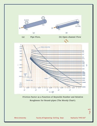
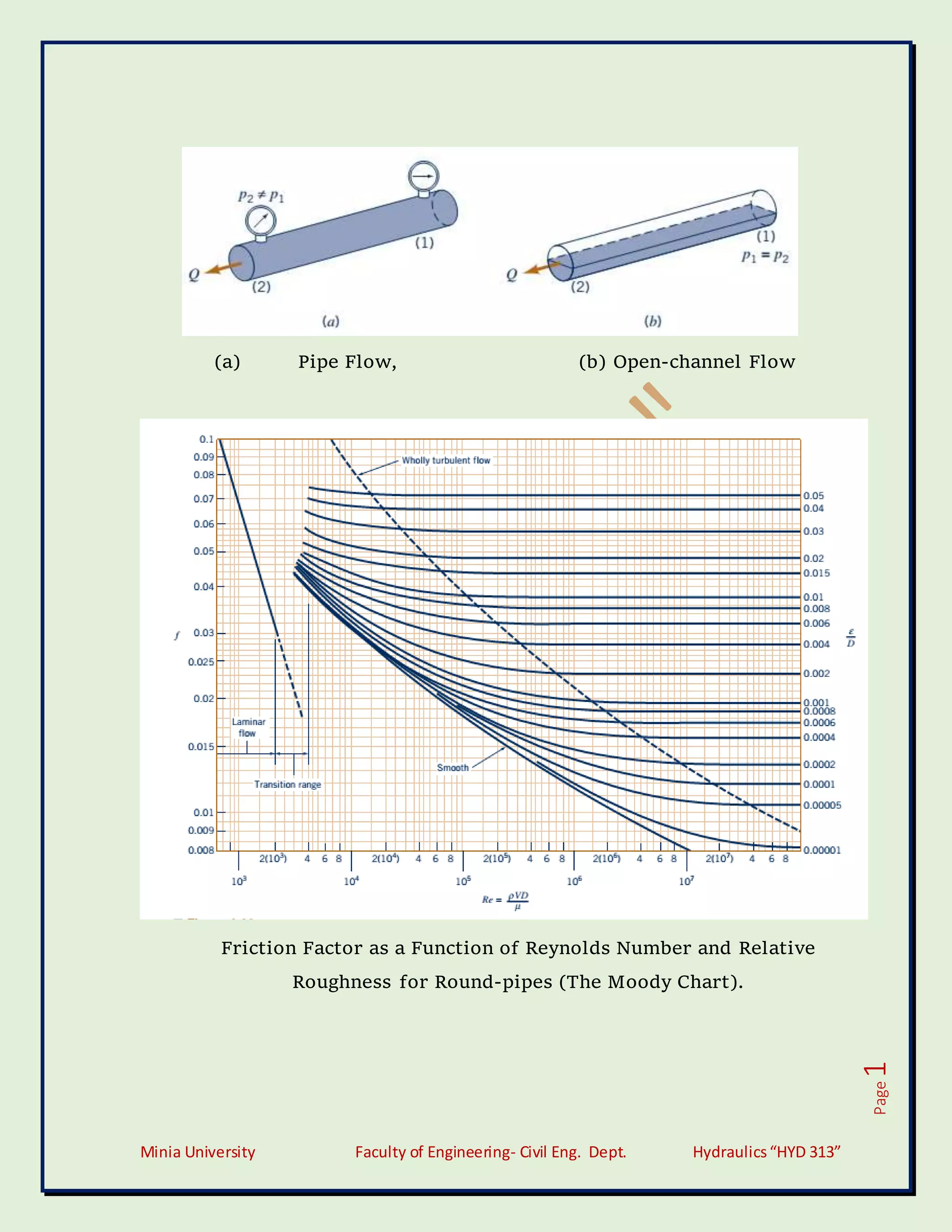
Moody’s diagram is accurate to about 15% for design calculations
and used for a large number of applications. It can be used for non-
circular conduits and also for open channels.
Define the terms:
a) Hydraulic gradient line [HGL]
b) Total Energy line [TEL]
Hydraulic gradient line: It is defined as the line which gives the sum
of pressure head and datum head of a flowing fluid in a pipe with
respect the reference line.
HGL = Sum of Pressure Head and Datum head
Total energy line: Total energy line is defined as the line which gives
the sum of pressure head, datum head and kinetic head of a flowing
fluid in a pipe with respect to some reference line.
TEL = Sum of Pressure Head, Datum head and Velocity head
T.E.L = Sum H.G.L + Velocity head
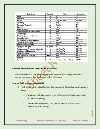
Write the dimensions for the followings.
21. Minia University Faculty of Engineering- Civil Eng. Dept. Hydraulics“HYD 313”
Page
21
What are fluid machines or Hydraulic machines?
The machines which use the liquid or gas for the transfer of energy from fluid to
rotor or from rotor to fluid are known as fluid machines.
How are fluid machines classified?
Fluid machines are classified into two categories depending upon transfer of
energy:
Turbines – hydraulic energy is converted to mechanical energy and
then electrical energy.
Pumps – electrical energy is converted to mechanical energy
and then hydraulic energy.
22. Minia University Faculty of Engineering- Civil Eng. Dept. Hydraulics“HYD 313”
Page
22
What are called turbines?
Hydraulic turbines are the machines which use the energy of water and
convert it into mechanical energy. The mechanical energy developed by a
turbine is used in running the electrical generator which is directly coupled to
the shaft.
A pipe network is represented in the following figure. All information is
shown in the figure. With the data shown, determine the flowrate in each
member of the system (Use Hardy Cross method).