Downloaded 125 times
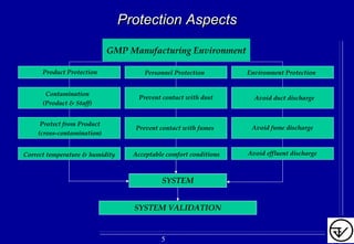
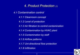
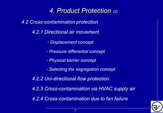
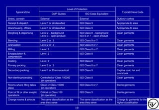
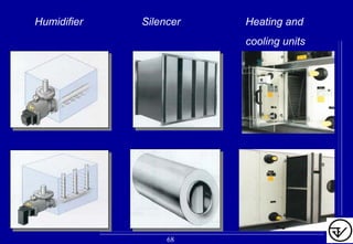

The document provides guidelines on good manufacturing practices for heating, ventilation and air conditioning (HVAC) systems for non-sterile oral solid dosage facilities. It discusses various aspects of HVAC system design including product protection, personnel protection, and environmental protection. Some key points include: - HVAC systems should be designed to prevent contamination and cross-contamination through control of air filtration levels, air flows, pressures differentials between rooms and other methods. - Areas are classified based on levels of protection from Level 1 to Level 3. Level 3 areas require the strictest controls on environmental conditions. - Uni-directional air flows and positive or negative pressure cascades between areas help control contamination risks.


