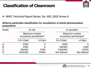
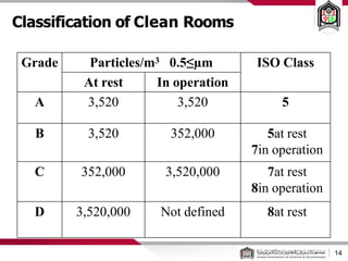
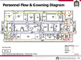
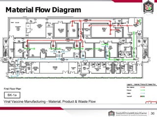
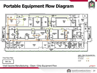
Call Girls Nagpur Just Call 9907093804 Top Class Call Girl Service Available
Clean Room Pharmaceutical Good Manufacturing Process.pdf
1. Cleanrooms and GMP
Design of Pharmaceutical
Facilities
Cleanrooms
Process design
Layoutsand Flow Diagrams
OSD Facilities
By: Dr. Mohammed Abdeen
Pharm. PhD
Pharmaceutics VII
2. Current Good Manufacturing Practices
(cGM)
2
• c G MP is a set of regulations published by the US Food
and Drug Administration (FDA)
• Most national and international agencies regulating
pharma industry have similar regulations or guidelines
• cGMP regulations cover many aspects: organization
and personnel, building and facilities, equipment,
control of components, production controls,
packaging and labeling controls, laboratory controls
etc.
4. 4
• Cleanrooms provide for the control of airborne contamination to
levels appropriate for accomplishing contamination-sensitive
activities.
– Aerospace,
– Microelectronics,
– Pharmaceuticals,
– Medical devices,
– Healthcare (Hospitals)
– Food.
Introduction:
5. 5
• Cleanroom can be defined through 2 areas:
Control: A space where the number of
airborne particles are measured. A space
where other environmental factors are
controlled (humidity, temperature, pressure)
Design: An enclosed space constructed in a
way to minimise the introduction, generation
and retention of particles.
What Is A Cleanroom?
6. 6
• Particle: Solid or liquid object which, for purposes of
classification of air cleanliness, falls within a threshold size in the
range from 0.1 to 5μm
• Occupancy states:
• As-built: installation is complete, all services functioning, no
production equipment, materials, or personnel present
• At-rest: equipment installed and operating in a manner
agreed upon the customer and supplier, but with no
personnel present
• Operational: the installation is functioning in the specified
manner, specified number of personnel present and working
Definitions
8. 8
• Classification:
level of airborne particulate cleanliness, represents
maximum allowable concentrations (in particles
per cubic metre of air) for considered sizes of
particles
• There are 9 ISO classifications, ISO 1, ISO 2, ISO 3,
……, and ISO 9.
• ISO 1 is considered the cleanest while ISO 9 is
considered the dirtiest.
Classification of Cleanroom
9. 9
Air Quality Monitoring
• Number of particles per
unit of air volume is tested
during facility qualification
and routinely. Such testing
is done both “at rest” (no
activity) and during normal
operations. Portable
(shown in the picture) or
permanently installed
particle counters may
be used.
10. 10
• The particulate cleanliness of air shall be defined in one
or more of three occupancy states, viz. “as-built”, “at-
rest”, or “operational”
• The maximum permitted concentration of particles, Cn,
for each considered particle size, D,
• In which, N is the ISO classification number, which shall
not exceed a value of 9. (ISO Class 1 to 9)
Classification of Cleanroom
14. Classification of Clean Rooms
14
Grade Particles/m3 ≥
0.5 µm ISO Class
At rest In operation
A 3,520 3,520 5
B 3,520 352,000 5at rest
7in operation
C 352,000 3,520,000 7at rest
8in operation
D 3,520,000 Not defined 8at rest
15. Classification of Cleanroom
15
• Typically, semi conductor, advanced engineering,
optics, laser and electronics require an ISO 5
cleanroom along with pharmaceutical and
medical devise companies. The reasons that
companies require these facilities vary from yield
(money) to safety (regulation).
16. Classification of Cleanroom
16
• Guidelines for required number of air changes:
• 240-480 changes/hr for Class A rooms
• 60-90 changes/hr for Class B rooms
• 20-40 changes/hr for Class C rooms
• These numbers are not regulations, just guidelines.
They vary in different sources.
17. Classification: PIC/S:
17
• The Pharmaceutical Inspection Convention and
Pharmaceutical Inspection Co-operation Scheme (PIC/S) are
two international instruments between countries and
pharmaceutical inspection authorities.
• The PIC/S is meant as an instrument to improve co-
operation in the field of Good Manufacturing Practices
between regulatory authorities and the pharmaceutical
industry.
18. Classification of Cleanroom
18
• Classification: PIC/S
Grade A: The local zone for high risk operations:
– Filling zone, open ampoules and vials, making aseptic
connections.
– Provided by a LAF work station with a homogeneous air
speed in a range of 0.36 – 0.54 m/s (guidance value)
– A unidirectional air flow and lower velocities may be
used in closed isolators and glove boxes.
Grade B: For aseptic preparation and filling, this is the
background environment for the grade A zone.
Grade C and D: Clean areas for carrying out less critical
stages in the manufacture of sterile products.
19. PIC/S General Paragraphs
19
Clean Areas:
• Entry through airlocks for personnel and/or for
equipment and materials.
• Supplied with air has passed through filters of
an appropriate efficiency.
The various operations of component preparation,
product preparation and filling in separate
areas within the clean area
Manufacturing operations:
1. Product is terminally sterilized,
2. Conducted aseptically at some or all stages.
In order to meet “in operation” conditions, areas
should be designed to reach certain air-cleanliness
levels in the “at rest” occupancy state.
20. PIC/S General Paragraphs
20
1- Terminally Sterilized Products
Preparation of components and most products should be
done in at least a grade D environment
Where the product is at a high or unusual risk of
microbial contamination Grade C
Filling of products for terminal sterilization Grade C
• Where the product is at unusual risk of contamination
from the environment, filling Grade A with Grade C
background.
Preparation and filling of ointments, creams, suspensions
and emulsions should grade C before terminal
sterilization
21. PIC/S General Paragraphs
21
2- Aseptic Preparation
Components after washing Grade D
Handling of sterile starting materials, unless
subjected to sterilization or filtration Grade A
with Grade B background.
Otherwise Grade C
Handling and filling of aseptically prepared
products Grade A
Transfer of partially closed containers, as used in
freeze drying, either in a Grade A environment
with grade B background or in sealed transfer trays
in a grade B environment
23. GMP Requirements Highlights
23
• Building shall be of suitable size, location
and construction, easily cleanable and
maintainable
• Building shall be designed to prevent equipment and
material mix-ups and contamination
• Separate areas shall be provided for different
operations
• Provide adequate control of air pressure,
microorganisms, dust, humidity and temperature as
appropriate
• Written procedures required for cleaning and sanitation
24. Process and Facility Design
24
• Facility design and layout must satisfy:
• Process requirements
• Personnel flows
• Material flows (raw materials and products)
• Equipment layout requirements
• Operational access requirements
• Maintenance access requirements
• Facility should be designed around process needs!
25. Planning and Design considerations
25
• A project plan shall be developed to define the requirements of
the products, the processes and the scope of the installation.
• A process equipment list shall be compiled, and shall include the
critical requirements for each piece of process equipment.
• Diversity factors shall be defined, considering peak and average
demand for each utility and environmental control system.
• A contamination control concept shall be developed for each
zone of an installation.
26. Planning and Design considerations
26
• For economic, technical and operational reasons, clean zones
are often enclosed or surrounded by further zones of lower
cleanliness.
• The zones with the highest cleanliness demands is reduced to
the minimum size.
• Movement of material and personnel between adjacent clean
zones gives rise to the risk of contamination transfer,
Management of material and personnel flow
32. Process Flow Diagrams (PFD’s)
32
• PFD’s are graphical representations of the manufacturing
process based on manufacturing instructions
• PFD’s are reference tools that support manufacturing and assist
engineers and constructors with developing facilities and
equipment design requirements.
• There are no universal standards for PFD’s. Each company uses its
own methodology and symbology.
• All PFD’s contain at a minimum the following basic information:
• Material balance and material streams based on formulation and
batch size
• Graphical representation of the major steps in the manufacturing
process
• Identification of the equipment used in the manufacturing process
35. Clean Room Features
35
• Walls and floors designed for easy cleaning, resistant
to wear and cleaning chemicals
• Coved floor and wall corners
• Minimize horizontal piping, ducts, equipment surfaces
where dust can accumulate
• Lighting is supplied by sealed fixtures, often
incorporated into ceiling HEPA filter modules.
36. Clean Room Features
36
• Typical clean room finishes include:
• Epoxy terrazzo floors
• Epoxy painted walls
• Suspended drywall or plaster ceiling, painted
for easy cleaning
• Clean rooms can be built at the site
or purchased as modules from a
vendor
37. Clean Room Features
37
Utility services and ancillary equipment:
– General: Utility services should be designed and installed such
that the cleanroom is not compromised by contamination.
– exposed piping, tubing and cable runs should be minimized,
– Vacuum-cleaning equipment
–– Communication systems: to reduce personnel movement
– Glazing: Avoid heat loss and solar gain, non-opening double
glaze
41. Unit Operations and Equipment
Applications
41
• Dispensing and Weighing
• Sifting and Classifying
• Milling
• Granulation
• Drying
• Blending
• Compression
• Encapsulation
• Coating
42. Dispensing
• Small Volume Dispensing
• Down Flow Laminar Flow Hoods
• Dedicated Rooms with
Environmental Controls
• Large Volume Dispensing
• Silos
• Super Sacks
• Pneumatic Conveyance and Weigh
Systems
• Gravity Transfer and Weigh Systems
42
43. Other Design Considerations
43
• Storage and handling of materials in bulk containers
(IBC), drums, bags, etc
• Material Handling Equipment
• Staging and Put Down Areas
• Wash Areas and Equipment Storage
• Pallet washers
• IBC washers
44. Sifting and Classifying
Purpose:
• De-lumping of powders
• Improve particle size
distribution - removal of
oversized and undersized
particles
Equipment:
• Vibratory screen sifters
• Manual sieves
44
46. Wet Granulation
• High Shear
Granulation
• High dispersion
• Improved
homogeneity
• Good for small
quantities of
actives
46
47. Wet Granulation cont’d
• Fluid Bed Granulation
• Control of particle size
• Materials that can not
withstand high shear
• Granules dried in same
machine
47
48. Drying
• Reduce moisture content
of granules to 2-5%
• Methods
• Fluid Bed Dryers
• Tray Dryers (ovens)
48
49. Blending
• Combine granulation with excipients and
lubricants
• Excipient - typically lactose
• Lubricants - typically magnesium stearate
added to improve flow properties
• Convection mixing
• Use of paddles or blades to achieve mixing
• Ribbon blenders, Orbital screw blenders,
planetary mixers, etc.
• Diffusion Blenders
• Use of Tumbling Action
• V Blenders, Cone Blenders, Bin Blenders
49
50. Tablet Compression
• Blend (powder or granules) is filled into die cavities
• Material is co mpressed into tablets
50
51. Encapsulation
• Capsules
• Hard gelatin capsules filled with
solids
• Final blend must be uniform
• Better for products with high API
content
• Filling done by volume, so
constant bulk density is important
51
52. Coating
• Coatings: Aqueous or Solvent Based
• Film coating
• Thin film ( 2 to 5 mils)
• Clear or with colorant
• Sugar coating
• Heavy - may reach 50%of tablet weight
• Enteric coatings
• Delay dissolution until the tablet reaches
the intestinal tract
• Bead Coating
• Time and sustained release products
52
53. Facility Layout
53
• Facility layout must:
• Provide short and logical routes for material and
personnel flow
• Avoid cross-flows whenever possible
• Provide means of separation for quarantined,
released and rejected materials
• Provide sufficient space for each operation,
including staging, washing and other ancillary
areas
• Help prevent cross-contamination
54. Layout of Mixing and Granulating
Areas
• Easy movement of materials
into separate processing
rooms
• Minimize cross-
contamination potential
• Air pressure in the corridor is
higher than in the process
rooms for product
containment
54
59. Inspect Vials
•Every vial must undergo
inspection:
– manual or automatic
–may be done in line with
the filling process - less
scratches – fewer rejected
vials
59
60. The Vial Filling Process
60
• The aseptic processing steps (where the
product and product contact parts are
exposed) are performed in a Class A / ISO5
environment
• The other classes are used for areas with
other activities depending on the potential
impact of on the process
61. The Vial Filling Process
61
• All steps involving clean operators and materials
must be separated from dirty operators and
waste. This requires separate airlocks and
corridors for the clean and dirty activities
(unidirectional flows)
• Even with all of these precautions (room
pressurization, airflow, airlocks, garbing and
treatment of materials) the ISO5 environment is
under constant assault by the most contaminate
object in the building - the operator
• To minimize the impact of the operator on the
process, manufacturers are turning to a new
technology – isolators or RABS
62. The Vial Filling Process
62
The equipment may be located in:
– Clean Room Environment (Traditional)
– Clean Room Environment & Restricted
Access Barrier Systems (RABS)
– Aseptic Filling Isolator
64. The Vial Filling Process
• Isolators:
– box around the process
– access the process via
gloves
– must be
decontaminated using
automated technology
(VHP or H2O2) b ecause
the clean zone is very
small
64
65.
66. The Vial Filling Process
66
• Advantages of isolators:
– The operator is removed from the process, so less product
risk
– Can be located in an ISO8 environment
• Reduced ISO5 area
• Reduced requirements for the sterile garb
• Fewer airlocks and material sanitization steps
– Material and people movement in the facility is simplified
– Cleaning and cleaning validation reduced
– Lower long term operation cost than traditional clean
room facility
68. The Vial Filling Process: Isolators or
RABS?
68
RABS
• Concept - to combine the
advantages of an isolator
with the flexibility of a clean
room
• In reality RABS has not solved
any of the perceived
disadvantages of an isolator.
Isolators are the future of aseptic processing.