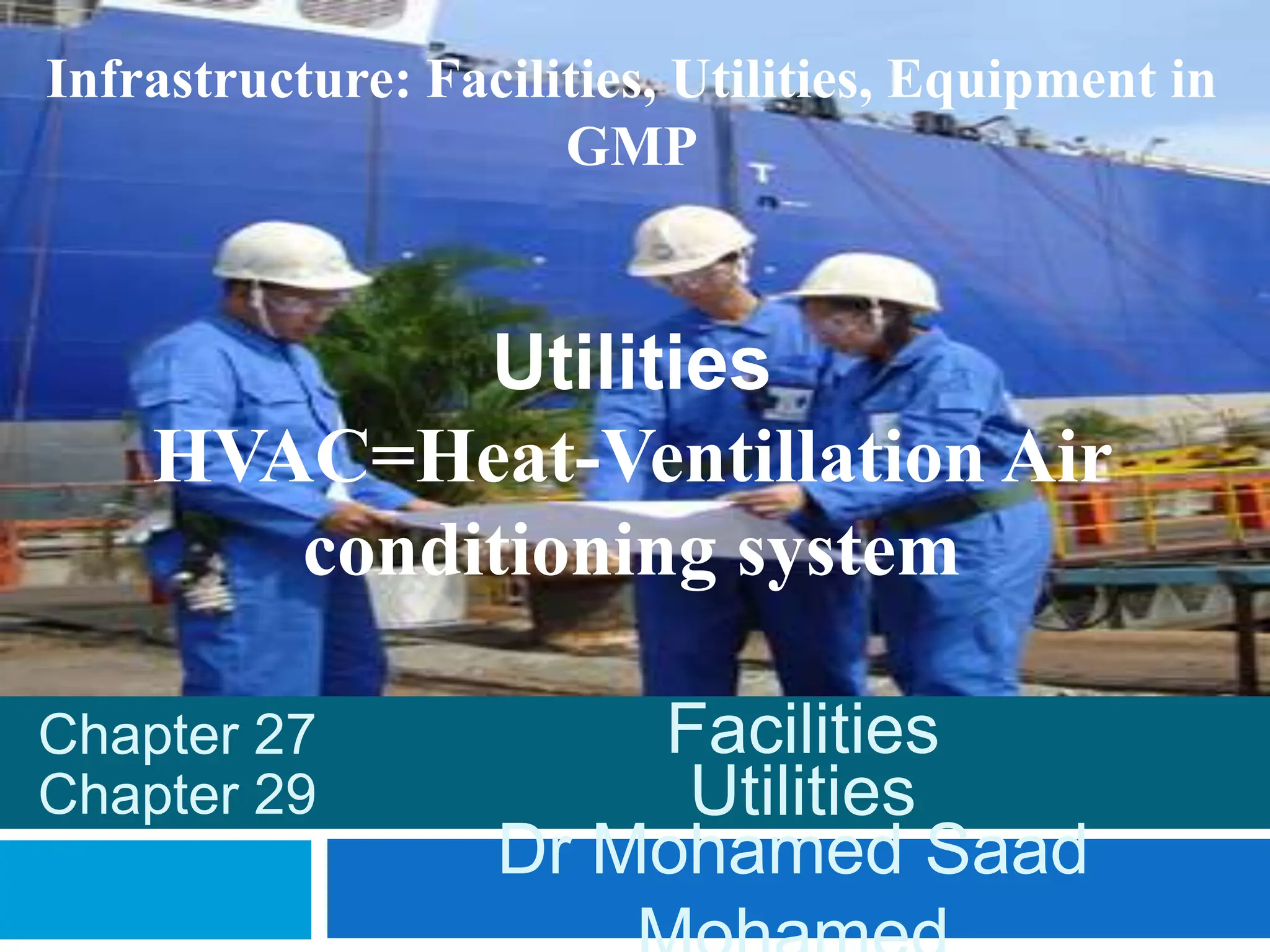
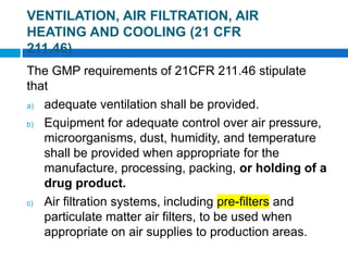
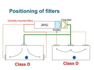
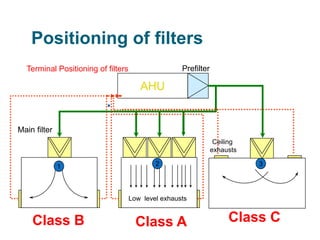
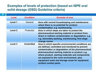
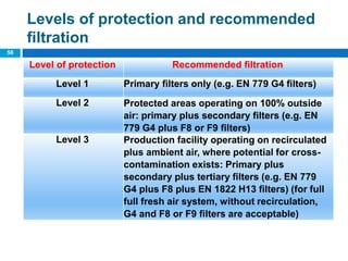
Infrastructure: Facilities, Utilities, Equipment in
GMP
Utilities
HVAC=Heat-Ventillation Air
conditioning system
Dr Mohamed Saad
Facilities
Chapter 27
Chapter 29 Utilities
The GMP requirements of 21CFR 211.46 stipulate
that
a) adequate ventilation shall be provided.
b) Equipment for adequate control over air pressure,
microorganisms, dust, humidity, and temperature
shall be provided when appropriate for the
manufacture, processing, packing, or holding of a
drug product.
c) Air filtration systems, including pre-filters and
particulate matter air filters, to be used when
appropriate on air supplies to production areas.
2 of 48
VENTILATION, AIR FILTRATION, AIR
HEATING AND COOLING (21 CFR
211.46)
 If air is recirculated to production areas, measures shall
be taken to control recirculation of dust from
production. ?????
 In areas where air contamination occurs during
production, exhaust systems or other systems
adequate to control contaminants are required.
d) Air-handling systems for the manufacture,
processing, and packing of penicillin are to be
completely separate from those for other drug
products for human use.
3 of 48
VENTILATION, AIR FILTRATION, AIR
HEATING AND COOLING (21 CFR
211.46)
 These systems should be closely monitored and
controlled.
 A company should generate a schedule for cleaning
and maintaining air vents, ducts, and cooling
systems.
 Human observation on a daily basis should also be
practiced. For example, visual observation of
blackened areas on vents is evidence that the
frequency of cleaning and maintenance needs to be
increased to avoid unwanted contaminants from
entering the area
4 of 48
VENTILATION, AIR FILTRATION, AIR
HEATING AND COOLING
What can HVAC do?
 Control airborne particles;
dust and micro-organisms – Thru air filtration using
high efficiency particulate air (HEPA) filters.
 Maintain room pressure (delta P);
Areas that must remain “cleaner” than surrounding
areas must be kept under a “positive”
pressurization, meaning that air flow must be from
the “cleaner” area towards the adjoining space
(through doors or other openings) to reduce carry
over of airborne contamination.
 Maintain space moisture (Relative Humidity);
Humidity is controlled by cooling air to dew
point= ‫الندى‬ ‫نقطة‬ temperatures or by using desiccant
dehumidifiers.
Humidity can affect the efficacy and stability of
drugs and is sometimes important to effectively
mould the tablets.
 Maintain temperature;
Temperature can affect production directly or
indirectly by fostering the growth of microbial
contaminants or uncomfortable environment for the
workers.
6
What can HVAC do?
What HVAC can’t do?
 HVAC can not clean up the
surfaces of a contaminated room
or equipment.
 HVAC can not compensate for
increased number of workers.
 In designing the air-conditioning
system for pharmaceutical plants,
it is very important to study the
application, identify various
factors affecting the particulate
count and decide the level of
contamination that can be
 Specific facility and process criteria define the system
solutions that are provided, Such as;
 Building construction and layout design.
 Temperature and Moisture.
 Air Cleanliness.
 Pressurization.
 Airflow pattern.
 AIR CHANGES
 Building Intake and Exhaust.
 Cost Considerations.
System Design
Considerations
Building construction and layout
design
 The internal generation of particles that consists of
those from building elements such as walls, floor,
ceiling, etc., from equipment, and most importantly
from operators can disrupt the cleanliness level.
 The building construction itself has to be "tight" with
minimum of uncontrolled infiltration and leakages.
 Proper building design and planning of the flow of
personnel, material and equipment is essential for
achieving and maintaining the designed levels of
cleanliness and pressure gradients.
9
Temperature and Moisture
 Space and process temperature and moisture
conditions are generally determined by the product or
process performed.
 Personnel comfort is also important, though
secondary to the product requirements.
Uncomfortable operators are more prone to commit
errors
 If products or processes are sensitive to moisture
and may even attract moisture hydroscopically, an
independent enclosed environment is often provided
(Level 3 protection).
10
 Areas are designed to provide room temperatures from
67 (20 °C) and 77°F (25 °C) with a control point of 72°F
(22 °C).
 While most of the areas could have a RH of 50 ± 5%.
 Facilities designed for handling hygroscopic powders
need to be at 30 ± 5%
 Relative humidity ranges must be carefully Selected;
 Continuous relative humidity levels below 15% can
cause static electricity discharge, health concerns,
and brittle hard gelatin capsule.
 Humidity levels above 60% can be the source of
microbial growth, support corrosion, and sticking of
tablets.
11
Temperature and Moisture
 HVAC Equipment is designed to meet the indoor
design criteria based on outdoor conditions and the
capacity of the equipment.
 If outdoor conditions are chosen too conservatively,
the equipment will be oversized, costing more than
required and possibly requiring more energy for
operation.
 If not, space or process conditions may not be met
12
Temperature and Moisture
Air Cleanliness
 The level of acceptable airborne contamination
within the space must be identified, whether
supporting product quality or employee safety.
 The resulting environmental cleanliness is
determined by several factors:
 The quality of air introduced into the space.
 The quantity of air introduced into the space.
 The effectiveness of air distribution through the
space.
 The effectiveness of the removal of the air
contaminants.
13
 Removal of the contaminant as close to its source
is always the most effective method of
contamination control—
 Whether it is central filtration at an air handling
unit before supply to the facility.
 Or dust collection at a point source of
contamination within a space.
14
Air Cleanliness
Pressurization
 Space relative pressurization will be determined primarily
by Requirements and Characteristics of the product that
may adversely effect personnel.
 Where product contamination control is required, the
space relative pressurization must be designed to assure
that the movement of filtrated air is from the clean to the
less clean areas.
 For a space requiring positive pressurization, the return
air volume is typically 15% less than the total supply
air volume.
 A pressure differential of at least 0.05 inches water gage
( 12.45 Pascal) with all doors closed is preferable
between spaces with a pressure differential requirement.
15
Typical Space Pressurization Configuratio
16
Pressurization
AIRFLOW PATTERN
 The air distribution has to be appropriate with the
class of cleanroom.
 Air turbulence in the space can cause particulates
which have settled onto the floor and work surfaces
to become re-entrained in the air.
 Air turbulence is greatly influenced by the
configuration of air supply and return grilles, people
traffic and process equipment layout.
17
The following measures are normally taken to control the
air flow pattern and hence the pressure gradient of the
sterile area:
 Class 100 and lower zones must necessarily have
unidirectional (laminar) flow with 100% HEPA filter
coverage in the ceiling or wall, and Return must be
picked up from the opposite side.
 Air flow velocities of 90 fpm ±20 (70 fpm to 110 fpm)
(0.45 m/s) are recommended as standard design for
Class 100 cleanroom systems.
 Class 1000 and above are generally non-unidirectional
with the supply air outlets at the ceiling level and the
return air at the floor level.
18
AIRFLOW PATTERN
AIR CHANGE RATES
 Air change rate is a measure of how quickly the air
in an interior space is replaced by outside (or
conditioned) air.
 Air flow rate/min = Air changes x Volume of space/
60
 Even though various design guidelines and
standards are available, there is no clear-cut
guidance for air changes per hour especially for
“sterile areas”.
 The goal is to achieve desired particulate
cleanliness levels and stay at or above a 20 air
changes/h minimum.
19
20
RECOMMENDED AIR CHANGE
RATES
Iso
14644-4 :
2001
NA
70-160
30-70
10-20
Building Intake and Exhaust
 Careful attention must be paid to the incoming
system air quality.
 This can be specific to the area in which the facility
has been constructed such as an agrarian or
industrial area.
 An industrial area may have a more corrosive or
chemical laden air quality and an agrarian area may
have a higher level of seasonal air borne particulate
and bio-burden.
 These issues must be carefully considered when
selecting filtration systems so as to minimize the
possibility of product contamination.
21
 Most often, however, building effluent re-
entrainment is the greater problem.
 Careful consideration must be made as to the
impacts of building exhaust and relief systems,
loading docks and other incidences of vehicle
exhaust and electrical generator exhaust.
 Analysis must be made of the subject building’s
impact on itself and other surrounding buildings.
22
Building Intake and Exhaust
Cost Considerations
 Pharmaceutical manufacturing facilities, utilities and
processes are extremely costly to design, construct,
and operate.
 When designing those, careful consideration must
be made of the initial construction cost, balanced
against life cycle operating costs.
 A cost cutting measure taken during the initial
capital expenditure can multiply into huge operating
costs by years of inefficient operation.
23
General
 Design of HVAC is dependent on required degree
of air cleanliness
 Suitable components should be selected including:
 AHU
 ducts
 grilles, etc.
HVAC Components
Filter
Silencer
Terminal filter
Weather louvre Control damper
Fan
Flow rate controller
Humidifier
Heating
coil
Cooling coil
with droplet
separator
Production Room
+
Prefilter
Exhaust Air Grille
Heater
Secondary Filter
Recirculated air
Overview components
 Weather Louvre
 Silencer
 Flow rate
controller
 Control damper
 To prevent insects, leaves, dirt and
rain from entering
 To reduce noise caused by air
circulation
 Automated adjustment of volume of
air (night and day, pressure control)
 Fixed adjustment of volume of air
Components (1)
HVAC Components
 Heating unit
 Cooling unit/
dehumidifier
 Humidifier
 Filters
 Ducts
 To heat the air to the proper
temperature
 To cool the air to the required
temperature or to remove moisture
from the air
 To bring the air to the proper
humidity, if too low.
 To eliminate particles of
predetermined dimensions and/or
microorganisms
 To transport the air
Components (2)
HVAC Components
What is the definition of the
AHU
 A factory-made encased assembly consisting
of a fan or fans and other necessary equipment
to perform one or more of the functions of
circulating, conditioning, and cleaning of air
 For pharmaceutical applications the unit casing
must be a double skin sandwich of metal with
insulation between the metal sheets to provide a
smooth, cleanable interior surface that does not
foster the growth of organisms.
 Units should contain access doors, view ports,
electrical convenience outlets, and interior lighting
for maintenance.
 The casings should be tightly sealed and designed
for high system air pressures required for
pharmaceutical applications.
29
What is the AHU
 All sealants and lubricants exposed to the airstream
should be food grade to minimize the chance of air
contamination.
 To avoid cross contamination independent air
handling systems should be provided for various
discrete operations like manufacturing, coating,
tableting, inspection and packing.
 In some departments there is further segregation of
operations which requires a certain degree of
control, if not an altogether independent air handling
unit.
30
What is the definition of the
AHU
31
What is the definition of the
AHU
How its work
 The flow passes through a damper, which can be
opened or closed to allow air to be taken into the unit.
 The air is subsequently filtered and passed through coils
that heat, cool, and dehumidify the flow.
 It should be noted that these coils are filled with primary
hot or chilled water from the boiler or chiller, respectively.
 The treated air, at the desired temperature and relative
humidity, is subsequently passed through a centrifugal
fan before it is directed to indoor spaces at the desired
flow rate using supply dampers.
AHU
Schematic of Air-Handler
Air-handling unit
Components in AHU may include, depending on need:
 Dampers.
 Fans; No fan failure; including supply air fans,
return air fans, exhaust air fan
 Dehumidifiers; Drying of air with chemical driers,
e.g. rotating desiccant wheel
 Humidifiers
 Coils; for heating and cooling air
 Filters.
 Ducts.
 Diffusers.
AHU Components
Filter Pressure
Gauges
AHU with fan Variable
Speed Controller
Dampers
• These dampers are located on
the suction side of the air fan.
• Proper access should be
provided in each section of the
air handling unit for routine
maintenance and cleaning.
• 100% intake damper is
especially useful during
“defumigation” operation
discussed later in the course.
Supply Blower Section
 Centrifugal fan is used to
circulate the air to the various
parts of the sections in the
building.
 The selection of the fan will
depend on the air volume and
the static pressure required ( to
compensate the back pressure
of HEPA filters ) of the system.
 Usually, the designer of the
system will use a specialized
software to do this selection.
Dehumidifiers
 Dehumidifiers are used to control relative humidity (RH)
to lower levels.
 RH of 50±5% can be achieved by cooling the air to the
appropriate dewpoint temperature.
 When chilled water is supplied at 5-7 °c to the cooling
coils, a minimum dew point of about 10-11°c can be
obtained.
 This results in a minimum room relative humidity of
approximately 50% at 21.11°c.
Dehumidifiers
 In some cases where hygroscopic (products sensitive to
moisture) materials are handled, the room RH
requirement may be as low as 30 to 35% and may
require the use of chemical dehumidifiers.
 Desiccant dehumidifiers work by drawing air across a rotating
wheel containing an absorption material, such as silica gel.
 As the air passes through the wheel, moisture is removed, the
wheel continues to rotate and is dried out using built in
heaters, then continues to remove more moisture form the air.
 They are often used in conjunction with heaters to boost the
drying process especially in cold weather conditions.
De-humidification
Filter Pressure
Gauges
AHU with fan Variable
Speed Controller
Humid room air
Air heater
Regeneration air
Humid room air
Adsorber wheel
Dry air
Dehumidifiers
Humidifiers
 In drier locations, makeup air may require the addition of
moisture for RH control.
 There are many commercially available humidifiers, but
the most commonly used is “steam grid” humidifier.
 These are controlled by modulation of a steam valve at
the humidifier, and include a chamber ( mix box) to
prevent condensation and water droplets in the duct.
 It is important to use clean steam, not plant steam, which
may contain boiler chemicals and impurities from
deteriorating piping and equipment.
Heating and Cooling Coil
 Cooling Coil is used to cool and dehumidify the air.
 Both DX (direct expansion) cooling and CW (chilled water)
cooling coils are available for use depending on the system
design.
 Chilled water or propylene glycol solutions are generally
used for cooling and dehumidification.
 Direct expansion refrigerant (DX), in which the refrigerant is
in the air unit coil, may be used, but these systems are less
reliable than chilled water or glycol and are more difficult to
control in the narrow air temperature ranges required with
higher running cost.
 In case of a heating coil, at least a 0.5 meter space should
be kept between coils.
43
Heating and Cooling Coil
Filters
 Proper air filtration is crucial for cleanroom controls.
 In dusty production areas such as grinding,
granulation, coating, tableting etc., the filters not only
control the atmosphere contamination but also hold
the internally generated particulates.
 Atmospheric dust is a mixture of dry particles, fibers,
mist, smoke, fumes, live or dead organisms.
 The air-borne particle size varies from 0.01 micron
to as much as 100 microns.
 Less than 10 micron particles are considered as
fine and particles over 10 micron is regarded as
“coarse”.
 Fine particles have longer airborne life time and
could settle on vertical surfaces.
 Coarse particles, products of mechanical abrasion
like in grinding and granulation departments, have
lower airborne life time and are subject to
gravitational settlement.
 The air conditioning systems in the pharmaceutical
industry have to handle both fine and coarse
particulates
45
Filters
Filters
 Air Filters
Air filters capture solid materials Can be
 “roughing” filter to capture a significant percentage
of total mass (30%)
 “high efficiency” to capture a higher percentage of
mass, plus some of the “weightless” fine particles
(85% - 95%)
 “high efficiency particulate” to remove virtually
100% of the material weight and 99.97% or more
of all particles
Filter classes Dust filters
Standard Aerosol
Fine
Coarse ULPA
HEPA
10 µ m > Dp > 1 µ m
Dp > 10 µ m Dp < 1 µ m
F5 - F9
G1 - G4 U 14- 17
H 11 - 13
EN 1822 Standard
EN 779 Standard
Filters
48
Primary panel filter Secondary filter HEPA or tertiary filter
Filters
Average Efficiency
Integral Value
Peak Arrestance
Local Value
Retention in
%
Penetration Efficiency Penetration
F9 85 0.15
H11 95 0.05
H12 99.5 5x10⁻³
97.5 25x10-3
H13 99.95 5x10⁻⁴
99.75 25x10-4
U14 99.995 5x10⁻⁵
99.975 25x10-5
Classification of filters according to their efficiency
Filters
 In order to prolong the service life of HEPA filters,
pre-filters are recommended to filter out majority of
particles above 1 micron.
 The filtration regime is generally three stages
with two stages of pre-filters, 10 micron (EU 4),
3 micron (EU 9) and one central final filter 0.3
micron (EU 13)
 Along with terminal HEPA filter if class c is
required..??
Pre-filters to HEPA Filters
A closer look at HEPA filters
 HEPA (High efficiency particulate air) filters have
99.97% to 99.997% removal efficiency on 0.3µ
particles.
 In other words, only less than 0.03% of all particles
of 0.3 microns or larger can get through such a filter.
 So if the return air contains 10,000 particles per ft3,
its concentration would be reduced down to three
particles per ft3 after it goes through the filter.
52
High Efficiency Particulate Air
(HEPA)
AHU
Prefilter
Final filter
2
1
Centrally mounted filters
Positioning of filters
Class D Class D
Prefilter
AHU
Main filter
1 2 3
Low level exhausts
Ceiling
exhausts
Terminal Positioning of filters
Positioning of filters
Class B Class A Class C
Examples of levels of protection (based on ISPE oral
solid dosage (OSD) Guideline criteria)
55
Level Condition Example of area
Level 1 General Area with normal housekeeping and maintenance
where there is no potential for product
contamination, e.g. warehousing.
Level 2 Protected Area in which steps are taken to protect the
pharmaceutical starting material or product from
direct or indirect contamination or degradation, e.g.
e.g. secondary packing, warehousing, first stage
change rooms.
Level 3 Controlled Area in which specific environmental conditions are
are defined, controlled and monitored to prevent
contamination or degradation of the pharmaceutical
pharmaceutical starting material or product, e.g.
where product, starting materials and components
are exposed to the room environment; plus
equipment wash and storage areas for equipment
product contact parts.
Levels of protection and recommended
filtration
56
Level of protection Recommended filtration
Level 1 Primary filters only (e.g. EN 779 G4 filters)
Level 2 Protected areas operating on 100% outside
air: primary plus secondary filters (e.g. EN
779 G4 plus F8 or F9 filters)
Level 3 Production facility operating on recirculated
plus ambient air, where potential for cross-
contamination exists: Primary plus
secondary plus tertiary filters (e.g. EN 779
G4 plus F8 plus EN 1822 H13 filters) (for full
full fresh air system, without recirculation,
G4 and F8 or F9 filters are acceptable)
Exhaust Fans
 Building exhausts are generally collected and
ducted to exhaust fans in groups or clusters.
 Fumes and toxic exhausts should be extended
through the roof and terminated well above the roof
line in a suitable stack head.
 Extremely toxic or dangerous active biological
agents may require HEPA filtration, before exhaust
to the atmosphere.
Return fans
 Are recommended on systems with long duct
returns to minimize suction pressure required from
the supply fan.
 If a return fan is not used, the capacity of the supply
fan can be overextended and it may be difficult to
limit and properly control the amount of outside air
being admitted to the unit.
 Return fans are also needed when required to
provide a negative pressure in rooms that require
containment.
Return fans
Air Handling Unit Location
 Air handling systems should be located on a
separate equipment floor or zone in order to
facilitate service and maintenance.
 They should also be located as close as possible to
the main rooms they are serving to minimize larger
and longer duct runs.
 Location of outdoor air-inlet louvers must be
carefully considered.
Air Handling Unit Location
 Intakes should be located on the building sidewall
high off the ground to minimize dust intake.
 Intakes should also be away from truck docks or
parking lots, where undesirable fumes and
particulate are generated.
 In locating inlets the prevailing winds should also be
considered, and any nearby exhausts or fume
concentrations should be avoided to prevent
recirculation of exhaust air back into the supply
system.
Air Handling Unit Location
Duct materials and shape
 Unlined galvanized steel, stainless steel or aluminum
ductwork is used in rectangular, round, and elliptical (or flat
oval) configurations for the majority of the systems.
 Round ducting is a natural choice, being self cleaning in
shape,
 When the HEPA filter is located upstream of the room terminal
and a long run of duct is present, the material of choice for the
duct is stainless steel, but this is expensive and its use should
be minimized.
 Many systems may also be fumigated or cleaned in place,
and the duct material chosen should not be affected by the
cleaning agent.
65
Duct materials and shape
Grilles and Diffusers
 A grille is a device for supplying or extracting
air vertically without any deflection.
 A diffuser normally has profiled blades
to direct the air at an angle as it leaves the unit
into the space.
 Grilles and Diffusers can be manufactured in:
 ALUMINUM
 Mild steel
 Stainless steel
 Plastic
 Air Grilles and Diffusers should be selected of materials
that are non-flaking, non-oxidizing, and are easily wiped
clean.
 Return Grilles are also an important consideration and
are generally located low in the walls for cleanrooms.
easily wiped clean.
Grilles and Diffusers
 Grilles and diffusers may be mounted in ceilings,
floors, walls, doors and in ducts.
 Floors grilles tend to be especially strong to
withstand foot traffic.
 Supply air outlets are mounted flush at the ceiling
level with perforated stainless steel grilles even if
terminal absolute filters.
Grilles and Diffusers
Low induction
swirl diffusor
(preferred)
High induction
office type diffusor
(avoid)
Grilles and Diffusers
 Supply air diffusers should be selected with care
taking consideration of, e.g. room requirements and
positions of equipment and operators in the room.
 Supply air diffusers of the high induction type (e.g.
those typically used for office-type air-conditioning)
should where possible not be used in clean areas
where dust is liberated.
 Air diffusers should be of the non- induction type,
introducing air with the least amount of induction so
as to maximize the flushing effect.
Grilles and Diffusers
 In rooms where the process results in high dust
liberation; perforated plates or low induction swirl
diffusers with low level extract or return should be
used (to contain the dust at the lower level of the
room)
 In cases where dust liberation is low, ceiling return air
grilles may be acceptable.
Grilles and Diffusers
AHU Pharmaceutical
requirements
 In order to meet the pharmaceutical requirements
the AHU`s should fulfill the following material
specification:
 Heating and cooling coils made of aluminum fins
with copper pipes The cooling coils are removable
 The frame of the coils will be galvanized steel
 The inner surface of the Air Handling Units and
the dampers will be galvanized steel or epoxy
coated
 Face velocity across coils is about 2.5m/s
 The pressure drop over the filter units will be
measured local.
 All equipment (coils, fan, filters) will be accessible
via doors
 All sections which are accessible are illuminated
and visible from the outside via small windows
 Frequency converters must start the fans
automatically in case of problem in electric supply.
AHU Pharmaceutical
requirements
Consider different air types, e.g.:
 Fresh air (make-up air)
 Supply air
 Return air (re-circulated air)
 Exhaust air
And: Concepts of air delivery to production areas:
 Once –thru Air (Ttal fresh-air systems) – Air is
conditioned, enters the space and is discarded
 Recirculation systems - Air is conditioned, enters the
space and portion is reconditioned. Some may be
discarded.
Air Types
+
Production Room
Exhaust
air
Return air
(recirculated)
Fresh air
(make-up air)
Supply
air
Air Types
 100% fresh air - normally where toxic products
are processed, and recirculation not
recommended.
 No contamination from fresh air – sufficient
filtration needed.
 Degree of filtration on exhaust dependent on
exhaust air contaminants and environment
regulations( usually through HEPA filter).
Once – Thru HVAC
Total fresh-air systems
Ventilation with 100% fresh air (no air recirculation)
W
Washer (optional)
Central Air-Handling Unit
Production Rooms
Exhaust Unit
Once – Thru HVAC
Total fresh-air systems
 Disadvantages
 Expensive to operate, especially when cooling and heating.
 Filter loading very high = frequent replacement.
 Potential need for dust collection/scrubbers/cleanouts in
exhaust line.
 Applications
 Labs with hoods, potential hazards
 Bulk Pharmaceutical Chemical (API) plants handling
flammable materials.
 Oral Solid Dosage (OSD) plants where potent
products/materials exposed.
 Where high potential of product cross-contamination –
segregation
Once – Thru HVAC
Total fresh-air systems
81 of 48
Once – Thru HVAC
Total fresh-air systems
 In pharmaceutical facilities large quantities of air may
be required to promote air cleanliness.
 In many cases the large quantities of air exceed the
requirements for cooling, so it is desirable and
possible to recirculate air within the space and only
pass enough air through the air handling unit to
perform the heating or cooling.
 The requirements ” There should be no risk of
contamination and cross-contamination when air is re-
circulated.”
 HEPA filters placed in AHU or terminally.
 Dust from highly toxic processes should not be re-
circulated
Recirculation systems
Ventilation with recirculated air + make-up air
Central Air-Handling Unit
Return air
Exhaust Unit
Recirculation systems
84 of 48
Recirculation systems
 What are advantages here?
 Usually less air filter loading = lower filter
maintenance.
 Opportunity for better air filtration.
 Less challenge to HVAC = better control of
parameters (T, RH, etc).
 lower cooling/heating cost.
85
Recirculation systems
 Disadvantages
 Chance of cross contamination = requires
adequate supply air filtration.
 Applications
 Classified spaces such as sterile manufacture
(few airborne materials, very clean return air)
 Finished oral solid dosage (OSD) manufacture in
single product facility or segregated areas.
86
Recirculation systems
HVAC automation system
provides
 HVAC automation system provides:
 Automatic emergency shutdown of ventilation and
air conditioning systems in case of a fire alarm.
 Automatic protection of coils against freezing.
 Maintain the required environmental conditions in
rooms.
BMS
88
BMS and EMS Systems
 The automatic control system that controls and monitors the
HVAC system is called by many names: the automatic
temperature control system (ATC), the energy management
and control system (EMCS), the building automation system
(BAS), or the building management system (BMS).
 A BMS, also referred to as a Building Automation System
(BAS), is a computer based control system installed in
facilities to control and monitor the facilities’ mechanical and
electrical equipment such as heating, cooling, ventilation,
lighting, power, fire, and security systems.
 In industries like aseptic manufacturing of pharmaceutical
medicinal products, facilities require Control (BMS) and
Monitoring (EMS) solutions.
 An EMS monitors environmental conditions that are
deemed GMP-critical, including parameters such as
particle counts, humidity, temperature, and pressure and
to monitor and record critical data logging of support
equipment such as fridges, freezers, incubators, or
product warehouse storage.
 All are GMP-critical for product release based on set
parameters for environmental and support equipment not
exceeding certain alarm set-points during the product
life-cycle from production to shipping.
 Some EMS systems utilize data logging sensors to
monitor transportation environments for products where
set environmental conditions must remain stable during
BMS and EMS Systems
Combining a BMS and an EMS
 Combining BMS and EMS requires a well-planned
risk assessment from conceptual design to
validation of the critical sensor devices that monitor
critical environmental parameters.
 Unfortunately, the level of risk becomes a question
of reliability when the control sensor is also used as
the monitoring sensor.
 Since the control aspect of the system is also the
GMP monitoring solution, there are some issues.
 If the control sensor was to drift, it would go on
unnoticed.
 Since most BMS system users do not regularly
calibrate the sensors, the chances of drift issues
becomes greater.
 With a separate EMS sensor, the drift would be
picked up immediately and when alarm limits exceed
the operating set-points, a responsible person would
be notified.
Combining a BMS and an EMS
 Another issue surrounding the use of a BMS and providing
GMP data is FDA 21 CFR Part 11 compliance. Many BMS
systems have not been designed to meet FDA 21CFR11
compliance and therefore the data could be rejected as true
compliant GMP data.
 EMS systems require strict security access control,
including audit trail, electronic records, and electronic
signatures in line with FDA 21 CFR Part 11 and PIC/S
Annex 11 on Computerized systems.
 If a BMS control system was also used to provide GMP
data, data integrity risks cannot be ignored, especially when
FDA and other regulatory bodies are scrutinizing data
integrity and validation.
Combining a BMS and an EMS
The Advantages of Separate BMS and
EMS
 The advantages of segregating a BMS and an EMS
should be considered and below are some of those
advantages outlined:
 With the EMS, all GMP data from critical environmental
locations is logged and stored on a secure database
that is backed up.
 The BMS does not require full validation however, it will
require a level of commissioning to verify control limits
and functions are working correctly.
 Having separate systems only requires validation of the
EMS system.
The Advantages of Separate BMS and
EMS
 If the BMS system experiences a software or sensor
failure, the EMS would continue to keep data records
from critical locations. For example, if product storage
equipment like a refrigerator was compromised, the
EMS would verify if the environment was compromised,
allowing for informed decisions to be made regarding
the release or rejection of valuable product.
 This is critical when there are temperature-sensitive
products.
 Regulatory auditors have been known to write up
deviations where a BMS are also designed to provide
GMP data.
EMS Minimum Requirements
 There are many EMS vendors on the market, so
choosing the right EMS is important, especially when
much ground work and research is required. The
following is a list of attributes an EMS should possess:
 Capable of immediate alert and action alarm
notifications.
 Provide a full audit trail capability,
 Designed to be FDA 21 CFR Part 11 and PIC/s Annex
11 compliant,
 Possess a redundancy and back-up system
automatically,
Commissioning
 Commissioning, as defined in the ASHRAE Guideline 1-
1996, is: The process of ensuring that systems are
designed, installed, functionally tested, and capable of
being operated and maintained to perform in conformity
with the design intent . . .
 Commissioning begins with planning and includes
design, construction, setting up, balancing, testing,
acceptance and training.
 Precursor to qualification
BALANCING
 For pharmaceutical facilities, establishing pressure
differentials between adjacent spaces is the most critical and
is very tedious to balance.
 These differentials are obtained by adjusting airflows, smoke
tests, taking pressure readings, and setting controls.
 This effort can take some time as each facility is different and
each room has different leakage characteristics that affect
pressurization.
 As part of the balancing, you may find that the duct systems
or rooms are not as tight as designed and may require
additional sealing to obtain the required pressure
differentials.
 A simple solution to many pressurization problems
is to keep increasing outdoor air to the system.
 This can lead to problems, if design values are
exceeded, with heating or cooling coils not
meeting this need, resulting in off-design room
temperatures and humidity levels.
 Therefore, the best solution first is to tighten the
spaces.
 The optimum time to balance is when few
construction workers or facility personnel are in
the spaces.
 The balance should be done with all doors closed,
since opening and closing results in system
pressure upsets and make balancing difficult.
BALANCING
Typical tests to be conducted after commissioning :
 Temperature
 Relative humidity
 Supply, return and exhaust air quantities
 Room air change rates
 Room pressures (pressure differentials)
 Room clean-up rate
 Particulate matter, microbial matter (viable and non-viable)
 HEPA filter penetration tests
 Containment system velocity
 Warning/alarm systems
Testing
VALIDATION
 NO production can start until the cleanrooms is
validated.
 When a pharmaceutical facility is to be validated, the
validating agency will peruse the HVAC documentation
and should communicate with the design engineers to
establish the validation protocol.
 The physical parameters reported by the BMS system
shall be verified by measurements using calibrated
instruments to verify accuracy.
 Usually done by third party to verify the correct function
of the system
DOCUMENTATION
 The documentation should cover
 Design qualification
 Installation qualification
 Operation qualification
 Performance qualification
 See also full guidelines on "Validation" in WHO TRS No
937, 2005, Annex 4.
Tests to demonstrate compliance TRS961 Annex 5
103
Test parameter Test procedure
Particle count test
(Verification of
cleanliness)
Dust particle counts to be carried out and result
printouts produced.
No. of readings and positions of tests to be in
accordance with ISO 14644-1 Annex B5
Air pressure difference
(To verify non cross-
contamination)
Log of pressure differential readings to be
produced or critical plants should be logged
daily, preferably continuously. A 15 Pa pressure
differential between different zones is
recommended. I
n accordance with ISO 14644-3 Annex B5
Airflow volume
(To verify air change
rates)
Airflow readings for supply air and return air
grilles to be measured and air change rates to be
be calculated.
In accordance with ISO 14644-3 Annex B13
104
Test parameter Test procedure
Airflow velocity
(To verify unidirectional
flow or containment
conditions)
Air velocities for containment systems and
unidirectional flow protection systems to be
measured.
In accordance with ISO 14644-3 Annex B4
Filter leakage tests
(To verify filter
integrity)
Filter penetration tests to be carried out by a
competent person to demonstrate filter media,
filter seal and filter frame integrity. Only required
on HEPA filters.
In accordance with ISO 14644-3 Annex B6
Containment leakage
(To verify absence of
cross-contamination)
Demonstrate that contaminant is maintained
within a room by means of: airflow direction
smoke tests room air pressures.
In accordance with ISO 14644-3 Annex B4
Tests to demonstrate compliance TRS961 Annex 5
105
Test parameter Test procedure
Recovery
(To verify clean-up
time)
Test to establish time that a cleanroom takes to
recover from a contaminated condition to the
specified cleanroom condition. Should not take
more than 15 min.
In accordance with ISO 14644-3 Annex B13*
Airflow visualization
(To verify required
airflow patterns)
Tests to demonstrate air flows:
•
from clean to dirty areas
•
do not cause cross-contaminationuniformly from
unidirectional airflow units Demonstrated by
actual or video-taped smoke tests.
•
In accordance with ISO 14644-3 Annex B7
Tests to demonstrate compliance TRS961 Annex 5
 See also ISO 14644 -2 fo
 Requalification, and change control.
 Tests performed according to protocols and
procedures for the tests.
 Results recorded and presented in report (source
data kept).
 Traceability, e.g. devices and standards used,
calibration records; and conditions specified.
HVAC Qualification
 Schedule of testing to demonstrate compliance with
particle concentration limits
107 of 48
Classification Maximum time interval Test method
≤ ISO Class 5 6 months Annex B in ISO 14644-1:1999
> ISO Class 5 12 months Annex B in ISO 14644-1:1999
NOTE Particle count tests will normally be performed in the operational state, but may
also be performed in the at-rest state in accordance with the designated ISO
classification.
ISO 14644-2:2000
 Schedule of additional tests for all classes
108 of 48
Test parameter Maximum time
interval
Test procedure
Airflow volume a or airflow
velocity
12 months ISO 14644-3:—, clause B.4
Air pressure difference 12 months ISO 14644-3:—, clause B.5
NOTE These tests may normally be performed in either the operational or at-rest
state in accordance with the designated ISO classification.
a. Airflow volume may be determined by either velocity or volume measurement
techniques.
b. This test will not apply to clean zones which are not totally enclosed.
ISO 14644-2:2000
 Schedule of optional tests
109 of 48
Test parameter Class Suggested
maximum time
interval
Test procedure
Installed filter
leakage
All classes 24 months ISO 14644-3:—, clause
B.6
Airflow
visualization
All classes 24 months ISO 14644-3:—, clause
B.7
Recovery All classes 24 months ISO 14644-3:—, clause
B.13
Containment
leakage
All classes 24 months ISO 14644-3:—, clause
B.14
ISO 14644-2:2000
Maintenance
 Procedure, programme and records for planned
preventative maintenance
 e.g. cleaning of filters, calibration of devices
 Appropriate training for personnel
 Change of HEPA filters by suitably trained persons
 Impact of maintenance on:
 Product quality
 Qualification
 Verification of design documentation, including
 description of installation and functions
 specification of the requirements
 Operating procedures
 Maintenance instructions
 Maintenance records
 Training logs
 Environmental records
 Discussion on actions if OOS values
 On site verification (walking around the site)
Inspecting the air-handling
system
18

HVAC System in pharmaceuticals industries .ppt

  • 1.
    Infrastructure: Facilities, Utilities,Equipment in GMP Utilities HVAC=Heat-Ventillation Air conditioning system Dr Mohamed Saad Facilities Chapter 27 Chapter 29 Utilities
  • 2.
    The GMP requirementsof 21CFR 211.46 stipulate that a) adequate ventilation shall be provided. b) Equipment for adequate control over air pressure, microorganisms, dust, humidity, and temperature shall be provided when appropriate for the manufacture, processing, packing, or holding of a drug product. c) Air filtration systems, including pre-filters and particulate matter air filters, to be used when appropriate on air supplies to production areas. 2 of 48 VENTILATION, AIR FILTRATION, AIR HEATING AND COOLING (21 CFR 211.46)
  • 3.
     If airis recirculated to production areas, measures shall be taken to control recirculation of dust from production. ?????  In areas where air contamination occurs during production, exhaust systems or other systems adequate to control contaminants are required. d) Air-handling systems for the manufacture, processing, and packing of penicillin are to be completely separate from those for other drug products for human use. 3 of 48 VENTILATION, AIR FILTRATION, AIR HEATING AND COOLING (21 CFR 211.46)
  • 4.
     These systemsshould be closely monitored and controlled.  A company should generate a schedule for cleaning and maintaining air vents, ducts, and cooling systems.  Human observation on a daily basis should also be practiced. For example, visual observation of blackened areas on vents is evidence that the frequency of cleaning and maintenance needs to be increased to avoid unwanted contaminants from entering the area 4 of 48 VENTILATION, AIR FILTRATION, AIR HEATING AND COOLING
  • 5.
    What can HVACdo?  Control airborne particles; dust and micro-organisms – Thru air filtration using high efficiency particulate air (HEPA) filters.  Maintain room pressure (delta P); Areas that must remain “cleaner” than surrounding areas must be kept under a “positive” pressurization, meaning that air flow must be from the “cleaner” area towards the adjoining space (through doors or other openings) to reduce carry over of airborne contamination.
  • 6.
     Maintain spacemoisture (Relative Humidity); Humidity is controlled by cooling air to dew point= ‫الندى‬ ‫نقطة‬ temperatures or by using desiccant dehumidifiers. Humidity can affect the efficacy and stability of drugs and is sometimes important to effectively mould the tablets.  Maintain temperature; Temperature can affect production directly or indirectly by fostering the growth of microbial contaminants or uncomfortable environment for the workers. 6 What can HVAC do?
  • 7.
    What HVAC can’tdo?  HVAC can not clean up the surfaces of a contaminated room or equipment.  HVAC can not compensate for increased number of workers.  In designing the air-conditioning system for pharmaceutical plants, it is very important to study the application, identify various factors affecting the particulate count and decide the level of contamination that can be
  • 8.
     Specific facilityand process criteria define the system solutions that are provided, Such as;  Building construction and layout design.  Temperature and Moisture.  Air Cleanliness.  Pressurization.  Airflow pattern.  AIR CHANGES  Building Intake and Exhaust.  Cost Considerations. System Design Considerations
  • 9.
    Building construction andlayout design  The internal generation of particles that consists of those from building elements such as walls, floor, ceiling, etc., from equipment, and most importantly from operators can disrupt the cleanliness level.  The building construction itself has to be "tight" with minimum of uncontrolled infiltration and leakages.  Proper building design and planning of the flow of personnel, material and equipment is essential for achieving and maintaining the designed levels of cleanliness and pressure gradients. 9
  • 10.
    Temperature and Moisture Space and process temperature and moisture conditions are generally determined by the product or process performed.  Personnel comfort is also important, though secondary to the product requirements. Uncomfortable operators are more prone to commit errors  If products or processes are sensitive to moisture and may even attract moisture hydroscopically, an independent enclosed environment is often provided (Level 3 protection). 10
  • 11.
     Areas aredesigned to provide room temperatures from 67 (20 °C) and 77°F (25 °C) with a control point of 72°F (22 °C).  While most of the areas could have a RH of 50 ± 5%.  Facilities designed for handling hygroscopic powders need to be at 30 ± 5%  Relative humidity ranges must be carefully Selected;  Continuous relative humidity levels below 15% can cause static electricity discharge, health concerns, and brittle hard gelatin capsule.  Humidity levels above 60% can be the source of microbial growth, support corrosion, and sticking of tablets. 11 Temperature and Moisture
  • 12.
     HVAC Equipmentis designed to meet the indoor design criteria based on outdoor conditions and the capacity of the equipment.  If outdoor conditions are chosen too conservatively, the equipment will be oversized, costing more than required and possibly requiring more energy for operation.  If not, space or process conditions may not be met 12 Temperature and Moisture
  • 13.
    Air Cleanliness  Thelevel of acceptable airborne contamination within the space must be identified, whether supporting product quality or employee safety.  The resulting environmental cleanliness is determined by several factors:  The quality of air introduced into the space.  The quantity of air introduced into the space.  The effectiveness of air distribution through the space.  The effectiveness of the removal of the air contaminants. 13
  • 14.
     Removal ofthe contaminant as close to its source is always the most effective method of contamination control—  Whether it is central filtration at an air handling unit before supply to the facility.  Or dust collection at a point source of contamination within a space. 14 Air Cleanliness
  • 15.
    Pressurization  Space relativepressurization will be determined primarily by Requirements and Characteristics of the product that may adversely effect personnel.  Where product contamination control is required, the space relative pressurization must be designed to assure that the movement of filtrated air is from the clean to the less clean areas.  For a space requiring positive pressurization, the return air volume is typically 15% less than the total supply air volume.  A pressure differential of at least 0.05 inches water gage ( 12.45 Pascal) with all doors closed is preferable between spaces with a pressure differential requirement. 15
  • 16.
    Typical Space PressurizationConfiguratio 16 Pressurization
  • 17.
    AIRFLOW PATTERN  Theair distribution has to be appropriate with the class of cleanroom.  Air turbulence in the space can cause particulates which have settled onto the floor and work surfaces to become re-entrained in the air.  Air turbulence is greatly influenced by the configuration of air supply and return grilles, people traffic and process equipment layout. 17
  • 18.
    The following measuresare normally taken to control the air flow pattern and hence the pressure gradient of the sterile area:  Class 100 and lower zones must necessarily have unidirectional (laminar) flow with 100% HEPA filter coverage in the ceiling or wall, and Return must be picked up from the opposite side.  Air flow velocities of 90 fpm ±20 (70 fpm to 110 fpm) (0.45 m/s) are recommended as standard design for Class 100 cleanroom systems.  Class 1000 and above are generally non-unidirectional with the supply air outlets at the ceiling level and the return air at the floor level. 18 AIRFLOW PATTERN
  • 19.
    AIR CHANGE RATES Air change rate is a measure of how quickly the air in an interior space is replaced by outside (or conditioned) air.  Air flow rate/min = Air changes x Volume of space/ 60  Even though various design guidelines and standards are available, there is no clear-cut guidance for air changes per hour especially for “sterile areas”.  The goal is to achieve desired particulate cleanliness levels and stay at or above a 20 air changes/h minimum. 19
  • 20.
    20 RECOMMENDED AIR CHANGE RATES Iso 14644-4: 2001 NA 70-160 30-70 10-20
  • 21.
    Building Intake andExhaust  Careful attention must be paid to the incoming system air quality.  This can be specific to the area in which the facility has been constructed such as an agrarian or industrial area.  An industrial area may have a more corrosive or chemical laden air quality and an agrarian area may have a higher level of seasonal air borne particulate and bio-burden.  These issues must be carefully considered when selecting filtration systems so as to minimize the possibility of product contamination. 21
  • 22.
     Most often,however, building effluent re- entrainment is the greater problem.  Careful consideration must be made as to the impacts of building exhaust and relief systems, loading docks and other incidences of vehicle exhaust and electrical generator exhaust.  Analysis must be made of the subject building’s impact on itself and other surrounding buildings. 22 Building Intake and Exhaust
  • 23.
    Cost Considerations  Pharmaceuticalmanufacturing facilities, utilities and processes are extremely costly to design, construct, and operate.  When designing those, careful consideration must be made of the initial construction cost, balanced against life cycle operating costs.  A cost cutting measure taken during the initial capital expenditure can multiply into huge operating costs by years of inefficient operation. 23
  • 24.
    General  Design ofHVAC is dependent on required degree of air cleanliness  Suitable components should be selected including:  AHU  ducts  grilles, etc. HVAC Components
  • 25.
    Filter Silencer Terminal filter Weather louvreControl damper Fan Flow rate controller Humidifier Heating coil Cooling coil with droplet separator Production Room + Prefilter Exhaust Air Grille Heater Secondary Filter Recirculated air Overview components
  • 26.
     Weather Louvre Silencer  Flow rate controller  Control damper  To prevent insects, leaves, dirt and rain from entering  To reduce noise caused by air circulation  Automated adjustment of volume of air (night and day, pressure control)  Fixed adjustment of volume of air Components (1) HVAC Components
  • 27.
     Heating unit Cooling unit/ dehumidifier  Humidifier  Filters  Ducts  To heat the air to the proper temperature  To cool the air to the required temperature or to remove moisture from the air  To bring the air to the proper humidity, if too low.  To eliminate particles of predetermined dimensions and/or microorganisms  To transport the air Components (2) HVAC Components
  • 28.
    What is thedefinition of the AHU  A factory-made encased assembly consisting of a fan or fans and other necessary equipment to perform one or more of the functions of circulating, conditioning, and cleaning of air
  • 29.
     For pharmaceuticalapplications the unit casing must be a double skin sandwich of metal with insulation between the metal sheets to provide a smooth, cleanable interior surface that does not foster the growth of organisms.  Units should contain access doors, view ports, electrical convenience outlets, and interior lighting for maintenance.  The casings should be tightly sealed and designed for high system air pressures required for pharmaceutical applications. 29 What is the AHU
  • 30.
     All sealantsand lubricants exposed to the airstream should be food grade to minimize the chance of air contamination.  To avoid cross contamination independent air handling systems should be provided for various discrete operations like manufacturing, coating, tableting, inspection and packing.  In some departments there is further segregation of operations which requires a certain degree of control, if not an altogether independent air handling unit. 30 What is the definition of the AHU
  • 31.
    31 What is thedefinition of the AHU
  • 32.
    How its work The flow passes through a damper, which can be opened or closed to allow air to be taken into the unit.  The air is subsequently filtered and passed through coils that heat, cool, and dehumidify the flow.  It should be noted that these coils are filled with primary hot or chilled water from the boiler or chiller, respectively.  The treated air, at the desired temperature and relative humidity, is subsequently passed through a centrifugal fan before it is directed to indoor spaces at the desired flow rate using supply dampers.
  • 33.
  • 34.
  • 35.
    Components in AHUmay include, depending on need:  Dampers.  Fans; No fan failure; including supply air fans, return air fans, exhaust air fan  Dehumidifiers; Drying of air with chemical driers, e.g. rotating desiccant wheel  Humidifiers  Coils; for heating and cooling air  Filters.  Ducts.  Diffusers. AHU Components
  • 36.
    Filter Pressure Gauges AHU withfan Variable Speed Controller Dampers • These dampers are located on the suction side of the air fan. • Proper access should be provided in each section of the air handling unit for routine maintenance and cleaning. • 100% intake damper is especially useful during “defumigation” operation discussed later in the course.
  • 37.
    Supply Blower Section Centrifugal fan is used to circulate the air to the various parts of the sections in the building.  The selection of the fan will depend on the air volume and the static pressure required ( to compensate the back pressure of HEPA filters ) of the system.  Usually, the designer of the system will use a specialized software to do this selection.
  • 38.
    Dehumidifiers  Dehumidifiers areused to control relative humidity (RH) to lower levels.  RH of 50±5% can be achieved by cooling the air to the appropriate dewpoint temperature.  When chilled water is supplied at 5-7 °c to the cooling coils, a minimum dew point of about 10-11°c can be obtained.  This results in a minimum room relative humidity of approximately 50% at 21.11°c.
  • 39.
    Dehumidifiers  In somecases where hygroscopic (products sensitive to moisture) materials are handled, the room RH requirement may be as low as 30 to 35% and may require the use of chemical dehumidifiers.  Desiccant dehumidifiers work by drawing air across a rotating wheel containing an absorption material, such as silica gel.  As the air passes through the wheel, moisture is removed, the wheel continues to rotate and is dried out using built in heaters, then continues to remove more moisture form the air.  They are often used in conjunction with heaters to boost the drying process especially in cold weather conditions.
  • 40.
    De-humidification Filter Pressure Gauges AHU withfan Variable Speed Controller Humid room air Air heater Regeneration air Humid room air Adsorber wheel Dry air Dehumidifiers
  • 41.
    Humidifiers  In drierlocations, makeup air may require the addition of moisture for RH control.  There are many commercially available humidifiers, but the most commonly used is “steam grid” humidifier.  These are controlled by modulation of a steam valve at the humidifier, and include a chamber ( mix box) to prevent condensation and water droplets in the duct.  It is important to use clean steam, not plant steam, which may contain boiler chemicals and impurities from deteriorating piping and equipment.
  • 42.
    Heating and CoolingCoil  Cooling Coil is used to cool and dehumidify the air.  Both DX (direct expansion) cooling and CW (chilled water) cooling coils are available for use depending on the system design.  Chilled water or propylene glycol solutions are generally used for cooling and dehumidification.  Direct expansion refrigerant (DX), in which the refrigerant is in the air unit coil, may be used, but these systems are less reliable than chilled water or glycol and are more difficult to control in the narrow air temperature ranges required with higher running cost.  In case of a heating coil, at least a 0.5 meter space should be kept between coils.
  • 43.
  • 44.
    Filters  Proper airfiltration is crucial for cleanroom controls.  In dusty production areas such as grinding, granulation, coating, tableting etc., the filters not only control the atmosphere contamination but also hold the internally generated particulates.  Atmospheric dust is a mixture of dry particles, fibers, mist, smoke, fumes, live or dead organisms.  The air-borne particle size varies from 0.01 micron to as much as 100 microns.
  • 45.
     Less than10 micron particles are considered as fine and particles over 10 micron is regarded as “coarse”.  Fine particles have longer airborne life time and could settle on vertical surfaces.  Coarse particles, products of mechanical abrasion like in grinding and granulation departments, have lower airborne life time and are subject to gravitational settlement.  The air conditioning systems in the pharmaceutical industry have to handle both fine and coarse particulates 45 Filters
  • 46.
    Filters  Air Filters Airfilters capture solid materials Can be  “roughing” filter to capture a significant percentage of total mass (30%)  “high efficiency” to capture a higher percentage of mass, plus some of the “weightless” fine particles (85% - 95%)  “high efficiency particulate” to remove virtually 100% of the material weight and 99.97% or more of all particles
  • 47.
    Filter classes Dustfilters Standard Aerosol Fine Coarse ULPA HEPA 10 µ m > Dp > 1 µ m Dp > 10 µ m Dp < 1 µ m F5 - F9 G1 - G4 U 14- 17 H 11 - 13 EN 1822 Standard EN 779 Standard Filters
  • 48.
    48 Primary panel filterSecondary filter HEPA or tertiary filter Filters
  • 49.
    Average Efficiency Integral Value PeakArrestance Local Value Retention in % Penetration Efficiency Penetration F9 85 0.15 H11 95 0.05 H12 99.5 5x10⁻³ 97.5 25x10-3 H13 99.95 5x10⁻⁴ 99.75 25x10-4 U14 99.995 5x10⁻⁵ 99.975 25x10-5 Classification of filters according to their efficiency Filters
  • 50.
     In orderto prolong the service life of HEPA filters, pre-filters are recommended to filter out majority of particles above 1 micron.  The filtration regime is generally three stages with two stages of pre-filters, 10 micron (EU 4), 3 micron (EU 9) and one central final filter 0.3 micron (EU 13)  Along with terminal HEPA filter if class c is required..?? Pre-filters to HEPA Filters
  • 51.
    A closer lookat HEPA filters
  • 52.
     HEPA (Highefficiency particulate air) filters have 99.97% to 99.997% removal efficiency on 0.3µ particles.  In other words, only less than 0.03% of all particles of 0.3 microns or larger can get through such a filter.  So if the return air contains 10,000 particles per ft3, its concentration would be reduced down to three particles per ft3 after it goes through the filter. 52 High Efficiency Particulate Air (HEPA)
  • 53.
    AHU Prefilter Final filter 2 1 Centrally mountedfilters Positioning of filters Class D Class D
  • 54.
    Prefilter AHU Main filter 1 23 Low level exhausts Ceiling exhausts Terminal Positioning of filters Positioning of filters Class B Class A Class C
  • 55.
    Examples of levelsof protection (based on ISPE oral solid dosage (OSD) Guideline criteria) 55 Level Condition Example of area Level 1 General Area with normal housekeeping and maintenance where there is no potential for product contamination, e.g. warehousing. Level 2 Protected Area in which steps are taken to protect the pharmaceutical starting material or product from direct or indirect contamination or degradation, e.g. e.g. secondary packing, warehousing, first stage change rooms. Level 3 Controlled Area in which specific environmental conditions are are defined, controlled and monitored to prevent contamination or degradation of the pharmaceutical pharmaceutical starting material or product, e.g. where product, starting materials and components are exposed to the room environment; plus equipment wash and storage areas for equipment product contact parts.
  • 56.
    Levels of protectionand recommended filtration 56 Level of protection Recommended filtration Level 1 Primary filters only (e.g. EN 779 G4 filters) Level 2 Protected areas operating on 100% outside air: primary plus secondary filters (e.g. EN 779 G4 plus F8 or F9 filters) Level 3 Production facility operating on recirculated plus ambient air, where potential for cross- contamination exists: Primary plus secondary plus tertiary filters (e.g. EN 779 G4 plus F8 plus EN 1822 H13 filters) (for full full fresh air system, without recirculation, G4 and F8 or F9 filters are acceptable)
  • 57.
    Exhaust Fans  Buildingexhausts are generally collected and ducted to exhaust fans in groups or clusters.  Fumes and toxic exhausts should be extended through the roof and terminated well above the roof line in a suitable stack head.  Extremely toxic or dangerous active biological agents may require HEPA filtration, before exhaust to the atmosphere.
  • 58.
    Return fans  Arerecommended on systems with long duct returns to minimize suction pressure required from the supply fan.  If a return fan is not used, the capacity of the supply fan can be overextended and it may be difficult to limit and properly control the amount of outside air being admitted to the unit.  Return fans are also needed when required to provide a negative pressure in rooms that require containment.
  • 59.
  • 60.
    Air Handling UnitLocation  Air handling systems should be located on a separate equipment floor or zone in order to facilitate service and maintenance.  They should also be located as close as possible to the main rooms they are serving to minimize larger and longer duct runs.  Location of outdoor air-inlet louvers must be carefully considered.
  • 61.
    Air Handling UnitLocation  Intakes should be located on the building sidewall high off the ground to minimize dust intake.  Intakes should also be away from truck docks or parking lots, where undesirable fumes and particulate are generated.  In locating inlets the prevailing winds should also be considered, and any nearby exhausts or fume concentrations should be avoided to prevent recirculation of exhaust air back into the supply system.
  • 62.
  • 63.
  • 64.
    Duct materials andshape  Unlined galvanized steel, stainless steel or aluminum ductwork is used in rectangular, round, and elliptical (or flat oval) configurations for the majority of the systems.  Round ducting is a natural choice, being self cleaning in shape,  When the HEPA filter is located upstream of the room terminal and a long run of duct is present, the material of choice for the duct is stainless steel, but this is expensive and its use should be minimized.  Many systems may also be fumigated or cleaned in place, and the duct material chosen should not be affected by the cleaning agent.
  • 65.
  • 66.
    Grilles and Diffusers A grille is a device for supplying or extracting air vertically without any deflection.  A diffuser normally has profiled blades to direct the air at an angle as it leaves the unit into the space.
  • 67.
     Grilles andDiffusers can be manufactured in:  ALUMINUM  Mild steel  Stainless steel  Plastic  Air Grilles and Diffusers should be selected of materials that are non-flaking, non-oxidizing, and are easily wiped clean.  Return Grilles are also an important consideration and are generally located low in the walls for cleanrooms. easily wiped clean. Grilles and Diffusers
  • 68.
     Grilles anddiffusers may be mounted in ceilings, floors, walls, doors and in ducts.  Floors grilles tend to be especially strong to withstand foot traffic.  Supply air outlets are mounted flush at the ceiling level with perforated stainless steel grilles even if terminal absolute filters. Grilles and Diffusers
  • 69.
  • 70.
  • 71.
    Low induction swirl diffusor (preferred) Highinduction office type diffusor (avoid) Grilles and Diffusers
  • 72.
     Supply airdiffusers should be selected with care taking consideration of, e.g. room requirements and positions of equipment and operators in the room.  Supply air diffusers of the high induction type (e.g. those typically used for office-type air-conditioning) should where possible not be used in clean areas where dust is liberated.  Air diffusers should be of the non- induction type, introducing air with the least amount of induction so as to maximize the flushing effect. Grilles and Diffusers
  • 73.
     In roomswhere the process results in high dust liberation; perforated plates or low induction swirl diffusers with low level extract or return should be used (to contain the dust at the lower level of the room)  In cases where dust liberation is low, ceiling return air grilles may be acceptable. Grilles and Diffusers
  • 74.
    AHU Pharmaceutical requirements  Inorder to meet the pharmaceutical requirements the AHU`s should fulfill the following material specification:  Heating and cooling coils made of aluminum fins with copper pipes The cooling coils are removable  The frame of the coils will be galvanized steel  The inner surface of the Air Handling Units and the dampers will be galvanized steel or epoxy coated  Face velocity across coils is about 2.5m/s
  • 75.
     The pressuredrop over the filter units will be measured local.  All equipment (coils, fan, filters) will be accessible via doors  All sections which are accessible are illuminated and visible from the outside via small windows  Frequency converters must start the fans automatically in case of problem in electric supply. AHU Pharmaceutical requirements
  • 76.
    Consider different airtypes, e.g.:  Fresh air (make-up air)  Supply air  Return air (re-circulated air)  Exhaust air And: Concepts of air delivery to production areas:  Once –thru Air (Ttal fresh-air systems) – Air is conditioned, enters the space and is discarded  Recirculation systems - Air is conditioned, enters the space and portion is reconditioned. Some may be discarded. Air Types
  • 77.
  • 78.
     100% freshair - normally where toxic products are processed, and recirculation not recommended.  No contamination from fresh air – sufficient filtration needed.  Degree of filtration on exhaust dependent on exhaust air contaminants and environment regulations( usually through HEPA filter). Once – Thru HVAC Total fresh-air systems
  • 79.
    Ventilation with 100%fresh air (no air recirculation) W Washer (optional) Central Air-Handling Unit Production Rooms Exhaust Unit Once – Thru HVAC Total fresh-air systems
  • 80.
     Disadvantages  Expensiveto operate, especially when cooling and heating.  Filter loading very high = frequent replacement.  Potential need for dust collection/scrubbers/cleanouts in exhaust line.  Applications  Labs with hoods, potential hazards  Bulk Pharmaceutical Chemical (API) plants handling flammable materials.  Oral Solid Dosage (OSD) plants where potent products/materials exposed.  Where high potential of product cross-contamination – segregation Once – Thru HVAC Total fresh-air systems
  • 81.
    81 of 48 Once– Thru HVAC Total fresh-air systems
  • 82.
     In pharmaceuticalfacilities large quantities of air may be required to promote air cleanliness.  In many cases the large quantities of air exceed the requirements for cooling, so it is desirable and possible to recirculate air within the space and only pass enough air through the air handling unit to perform the heating or cooling.  The requirements ” There should be no risk of contamination and cross-contamination when air is re- circulated.”  HEPA filters placed in AHU or terminally.  Dust from highly toxic processes should not be re- circulated Recirculation systems
  • 83.
    Ventilation with recirculatedair + make-up air Central Air-Handling Unit Return air Exhaust Unit Recirculation systems
  • 84.
  • 85.
     What areadvantages here?  Usually less air filter loading = lower filter maintenance.  Opportunity for better air filtration.  Less challenge to HVAC = better control of parameters (T, RH, etc).  lower cooling/heating cost. 85 Recirculation systems
  • 86.
     Disadvantages  Chanceof cross contamination = requires adequate supply air filtration.  Applications  Classified spaces such as sterile manufacture (few airborne materials, very clean return air)  Finished oral solid dosage (OSD) manufacture in single product facility or segregated areas. 86 Recirculation systems
  • 87.
    HVAC automation system provides HVAC automation system provides:  Automatic emergency shutdown of ventilation and air conditioning systems in case of a fire alarm.  Automatic protection of coils against freezing.  Maintain the required environmental conditions in rooms.
  • 88.
  • 89.
    BMS and EMSSystems  The automatic control system that controls and monitors the HVAC system is called by many names: the automatic temperature control system (ATC), the energy management and control system (EMCS), the building automation system (BAS), or the building management system (BMS).  A BMS, also referred to as a Building Automation System (BAS), is a computer based control system installed in facilities to control and monitor the facilities’ mechanical and electrical equipment such as heating, cooling, ventilation, lighting, power, fire, and security systems.  In industries like aseptic manufacturing of pharmaceutical medicinal products, facilities require Control (BMS) and Monitoring (EMS) solutions.
  • 90.
     An EMSmonitors environmental conditions that are deemed GMP-critical, including parameters such as particle counts, humidity, temperature, and pressure and to monitor and record critical data logging of support equipment such as fridges, freezers, incubators, or product warehouse storage.  All are GMP-critical for product release based on set parameters for environmental and support equipment not exceeding certain alarm set-points during the product life-cycle from production to shipping.  Some EMS systems utilize data logging sensors to monitor transportation environments for products where set environmental conditions must remain stable during BMS and EMS Systems
  • 91.
    Combining a BMSand an EMS  Combining BMS and EMS requires a well-planned risk assessment from conceptual design to validation of the critical sensor devices that monitor critical environmental parameters.  Unfortunately, the level of risk becomes a question of reliability when the control sensor is also used as the monitoring sensor.  Since the control aspect of the system is also the GMP monitoring solution, there are some issues.
  • 92.
     If thecontrol sensor was to drift, it would go on unnoticed.  Since most BMS system users do not regularly calibrate the sensors, the chances of drift issues becomes greater.  With a separate EMS sensor, the drift would be picked up immediately and when alarm limits exceed the operating set-points, a responsible person would be notified. Combining a BMS and an EMS
  • 93.
     Another issuesurrounding the use of a BMS and providing GMP data is FDA 21 CFR Part 11 compliance. Many BMS systems have not been designed to meet FDA 21CFR11 compliance and therefore the data could be rejected as true compliant GMP data.  EMS systems require strict security access control, including audit trail, electronic records, and electronic signatures in line with FDA 21 CFR Part 11 and PIC/S Annex 11 on Computerized systems.  If a BMS control system was also used to provide GMP data, data integrity risks cannot be ignored, especially when FDA and other regulatory bodies are scrutinizing data integrity and validation. Combining a BMS and an EMS
  • 94.
    The Advantages ofSeparate BMS and EMS  The advantages of segregating a BMS and an EMS should be considered and below are some of those advantages outlined:  With the EMS, all GMP data from critical environmental locations is logged and stored on a secure database that is backed up.  The BMS does not require full validation however, it will require a level of commissioning to verify control limits and functions are working correctly.  Having separate systems only requires validation of the EMS system.
  • 95.
    The Advantages ofSeparate BMS and EMS  If the BMS system experiences a software or sensor failure, the EMS would continue to keep data records from critical locations. For example, if product storage equipment like a refrigerator was compromised, the EMS would verify if the environment was compromised, allowing for informed decisions to be made regarding the release or rejection of valuable product.  This is critical when there are temperature-sensitive products.  Regulatory auditors have been known to write up deviations where a BMS are also designed to provide GMP data.
  • 96.
    EMS Minimum Requirements There are many EMS vendors on the market, so choosing the right EMS is important, especially when much ground work and research is required. The following is a list of attributes an EMS should possess:  Capable of immediate alert and action alarm notifications.  Provide a full audit trail capability,  Designed to be FDA 21 CFR Part 11 and PIC/s Annex 11 compliant,  Possess a redundancy and back-up system automatically,
  • 97.
    Commissioning  Commissioning, asdefined in the ASHRAE Guideline 1- 1996, is: The process of ensuring that systems are designed, installed, functionally tested, and capable of being operated and maintained to perform in conformity with the design intent . . .  Commissioning begins with planning and includes design, construction, setting up, balancing, testing, acceptance and training.  Precursor to qualification
  • 98.
    BALANCING  For pharmaceuticalfacilities, establishing pressure differentials between adjacent spaces is the most critical and is very tedious to balance.  These differentials are obtained by adjusting airflows, smoke tests, taking pressure readings, and setting controls.  This effort can take some time as each facility is different and each room has different leakage characteristics that affect pressurization.  As part of the balancing, you may find that the duct systems or rooms are not as tight as designed and may require additional sealing to obtain the required pressure differentials.
  • 99.
     A simplesolution to many pressurization problems is to keep increasing outdoor air to the system.  This can lead to problems, if design values are exceeded, with heating or cooling coils not meeting this need, resulting in off-design room temperatures and humidity levels.  Therefore, the best solution first is to tighten the spaces.  The optimum time to balance is when few construction workers or facility personnel are in the spaces.  The balance should be done with all doors closed, since opening and closing results in system pressure upsets and make balancing difficult. BALANCING
  • 100.
    Typical tests tobe conducted after commissioning :  Temperature  Relative humidity  Supply, return and exhaust air quantities  Room air change rates  Room pressures (pressure differentials)  Room clean-up rate  Particulate matter, microbial matter (viable and non-viable)  HEPA filter penetration tests  Containment system velocity  Warning/alarm systems Testing
  • 101.
    VALIDATION  NO productioncan start until the cleanrooms is validated.  When a pharmaceutical facility is to be validated, the validating agency will peruse the HVAC documentation and should communicate with the design engineers to establish the validation protocol.  The physical parameters reported by the BMS system shall be verified by measurements using calibrated instruments to verify accuracy.  Usually done by third party to verify the correct function of the system
  • 102.
    DOCUMENTATION  The documentationshould cover  Design qualification  Installation qualification  Operation qualification  Performance qualification  See also full guidelines on "Validation" in WHO TRS No 937, 2005, Annex 4.
  • 103.
    Tests to demonstratecompliance TRS961 Annex 5 103 Test parameter Test procedure Particle count test (Verification of cleanliness) Dust particle counts to be carried out and result printouts produced. No. of readings and positions of tests to be in accordance with ISO 14644-1 Annex B5 Air pressure difference (To verify non cross- contamination) Log of pressure differential readings to be produced or critical plants should be logged daily, preferably continuously. A 15 Pa pressure differential between different zones is recommended. I n accordance with ISO 14644-3 Annex B5 Airflow volume (To verify air change rates) Airflow readings for supply air and return air grilles to be measured and air change rates to be be calculated. In accordance with ISO 14644-3 Annex B13
  • 104.
    104 Test parameter Testprocedure Airflow velocity (To verify unidirectional flow or containment conditions) Air velocities for containment systems and unidirectional flow protection systems to be measured. In accordance with ISO 14644-3 Annex B4 Filter leakage tests (To verify filter integrity) Filter penetration tests to be carried out by a competent person to demonstrate filter media, filter seal and filter frame integrity. Only required on HEPA filters. In accordance with ISO 14644-3 Annex B6 Containment leakage (To verify absence of cross-contamination) Demonstrate that contaminant is maintained within a room by means of: airflow direction smoke tests room air pressures. In accordance with ISO 14644-3 Annex B4 Tests to demonstrate compliance TRS961 Annex 5
  • 105.
    105 Test parameter Testprocedure Recovery (To verify clean-up time) Test to establish time that a cleanroom takes to recover from a contaminated condition to the specified cleanroom condition. Should not take more than 15 min. In accordance with ISO 14644-3 Annex B13* Airflow visualization (To verify required airflow patterns) Tests to demonstrate air flows: • from clean to dirty areas • do not cause cross-contaminationuniformly from unidirectional airflow units Demonstrated by actual or video-taped smoke tests. • In accordance with ISO 14644-3 Annex B7 Tests to demonstrate compliance TRS961 Annex 5
  • 106.
     See alsoISO 14644 -2 fo  Requalification, and change control.  Tests performed according to protocols and procedures for the tests.  Results recorded and presented in report (source data kept).  Traceability, e.g. devices and standards used, calibration records; and conditions specified. HVAC Qualification
  • 107.
     Schedule oftesting to demonstrate compliance with particle concentration limits 107 of 48 Classification Maximum time interval Test method ≤ ISO Class 5 6 months Annex B in ISO 14644-1:1999 > ISO Class 5 12 months Annex B in ISO 14644-1:1999 NOTE Particle count tests will normally be performed in the operational state, but may also be performed in the at-rest state in accordance with the designated ISO classification. ISO 14644-2:2000
  • 108.
     Schedule ofadditional tests for all classes 108 of 48 Test parameter Maximum time interval Test procedure Airflow volume a or airflow velocity 12 months ISO 14644-3:—, clause B.4 Air pressure difference 12 months ISO 14644-3:—, clause B.5 NOTE These tests may normally be performed in either the operational or at-rest state in accordance with the designated ISO classification. a. Airflow volume may be determined by either velocity or volume measurement techniques. b. This test will not apply to clean zones which are not totally enclosed. ISO 14644-2:2000
  • 109.
     Schedule ofoptional tests 109 of 48 Test parameter Class Suggested maximum time interval Test procedure Installed filter leakage All classes 24 months ISO 14644-3:—, clause B.6 Airflow visualization All classes 24 months ISO 14644-3:—, clause B.7 Recovery All classes 24 months ISO 14644-3:—, clause B.13 Containment leakage All classes 24 months ISO 14644-3:—, clause B.14 ISO 14644-2:2000
  • 110.
    Maintenance  Procedure, programmeand records for planned preventative maintenance  e.g. cleaning of filters, calibration of devices  Appropriate training for personnel  Change of HEPA filters by suitably trained persons  Impact of maintenance on:  Product quality  Qualification
  • 111.
     Verification ofdesign documentation, including  description of installation and functions  specification of the requirements  Operating procedures  Maintenance instructions  Maintenance records  Training logs  Environmental records  Discussion on actions if OOS values  On site verification (walking around the site) Inspecting the air-handling system
  • 112.

Editor's Notes

  • #3 A prefilter is a type of filter that is installed in an HVAC system to capture large particles of dust, dirt, and other contaminants before they reach the main air filter. Prefilters are typically made of a coarse material that can trap larger particles that can cause damage or reduce the efficiency of the HVAC system's main filter. Prefilters are often used in HVAC systems to extend the life of the main filter, as the main filter can become clogged more quickly if it is forced to capture large particles. Prefilters can also help to improve indoor air quality by capturing larger particles before they are circulated throughout the building. They are often used in industrial and commercial HVAC systems, but can also be found in some residential HVAC systems. Prefilters should be cleaned or replaced regularly to ensure they continue to capture large particles effectively. The frequency of cleaning or replacement will depend on the specific HVAC system and the level of contaminants in the indoor environment.
  • #7 The dew point temperature is the temperature at which the air is completely saturated with water vapor, meaning it is holding as much moisture as it can. At this point, the air can no longer hold any more water vapor, so any additional moisture in the air will start to condense into liquid form, such as droplets of water on surfaces.
  • #9  refer to the factors that must be taken into account when designing an HVAC (Heating, Ventilation, and Air Conditioning) system for a building.
  • #25 13 July, 2024
  • #26 13 July, 2024
  • #27 13 July, 2024
  • #28 13 July, 2024
  • #36 13 July, 2024
  • #37 13 July, 2024
  • #41 13 July, 2024
  • #48 13 July, 2024
  • #50 13 July, 2024
  • #54 13 July, 2024
  • #55 13 July, 2024
  • #72 13 July, 2024
  • #77 13 July, 2024
  • #78 13 July, 2024
  • #79 13 July, 2024
  • #80 13 July, 2024
  • #83 13 July, 2024
  • #84 13 July, 2024
  • #98 13 July, 2024
  • #101 13 July, 2024
  • #107 13 July, 2024
  • #111 13 July, 2024
  • #112 13 July, 2024