The document discusses design requirements for aseptic manufacturing facilities. Key points include:
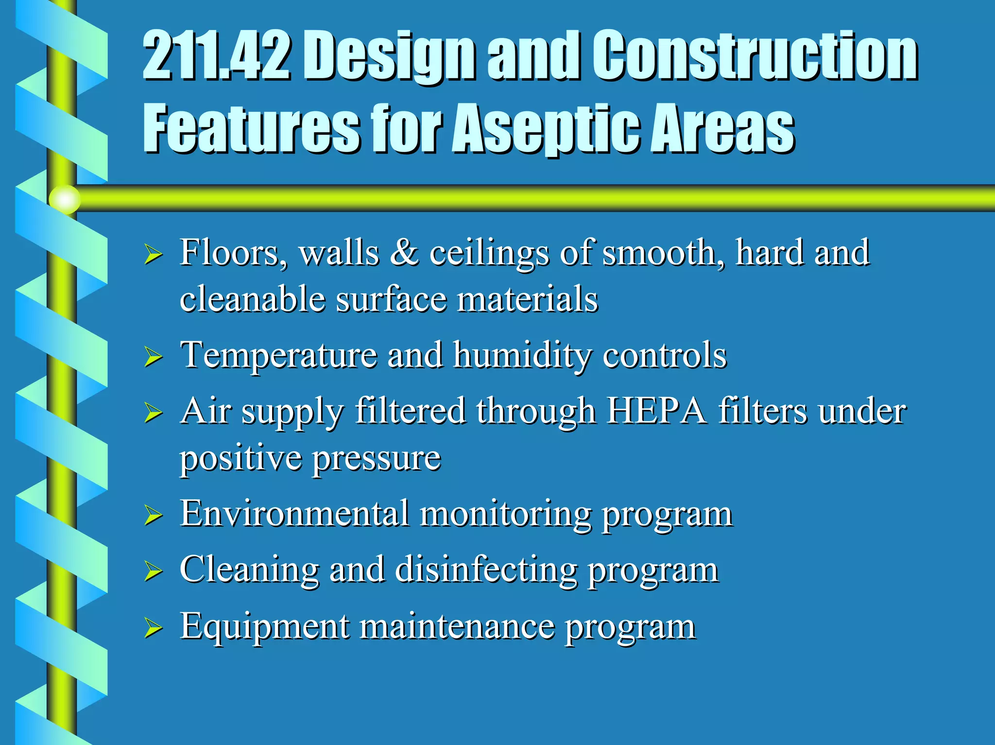
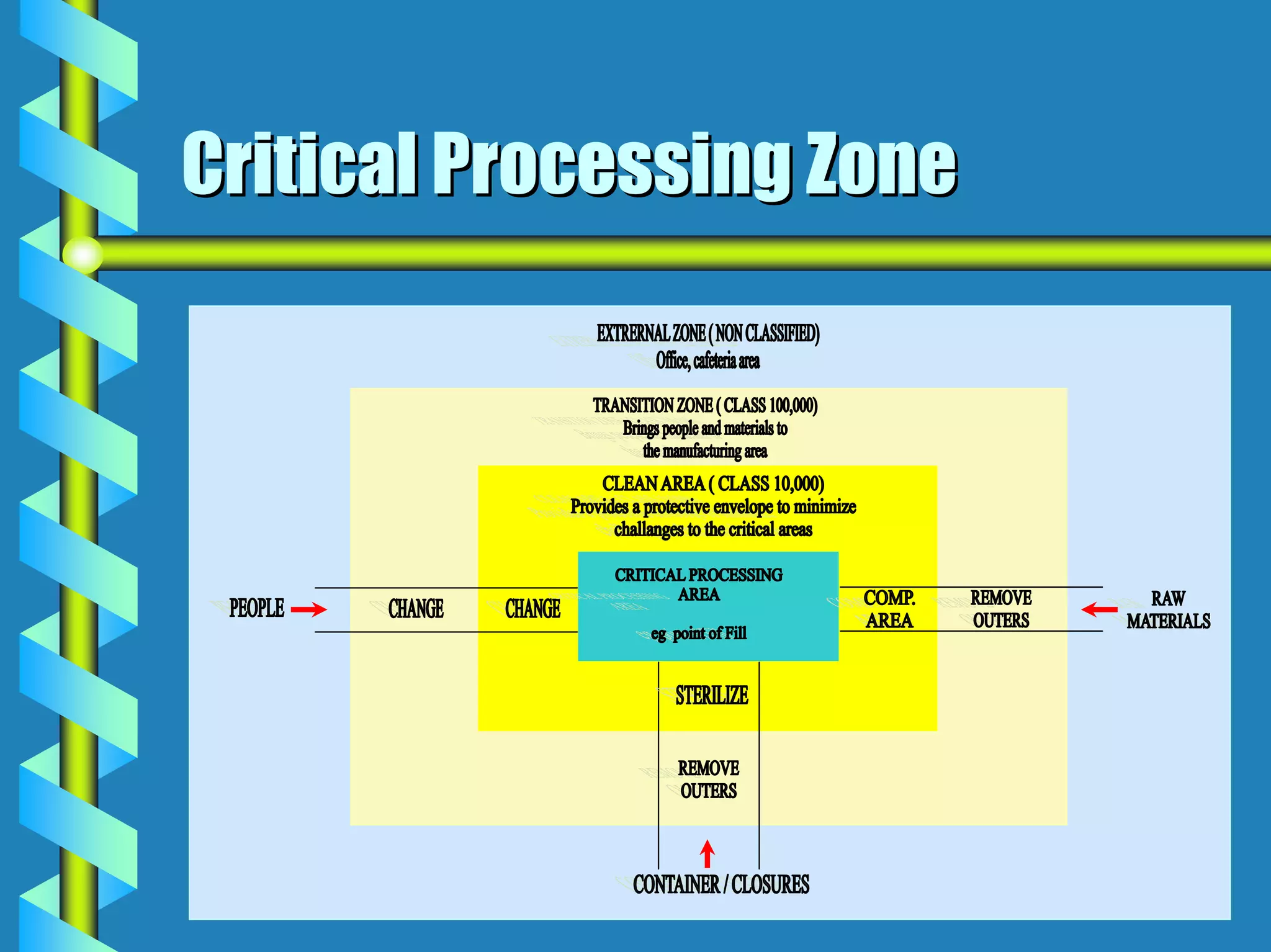
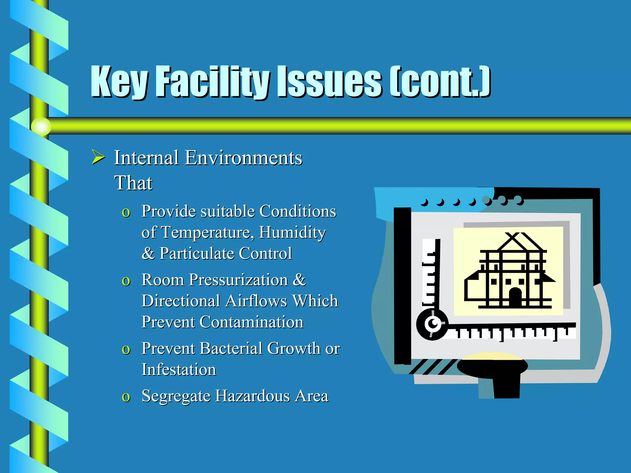
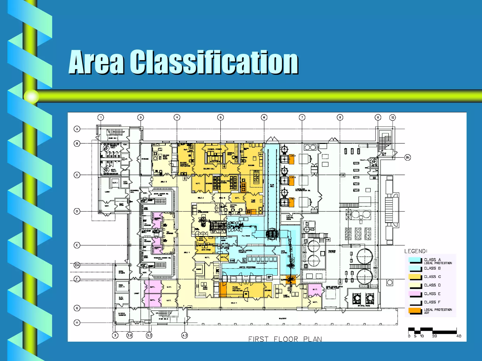
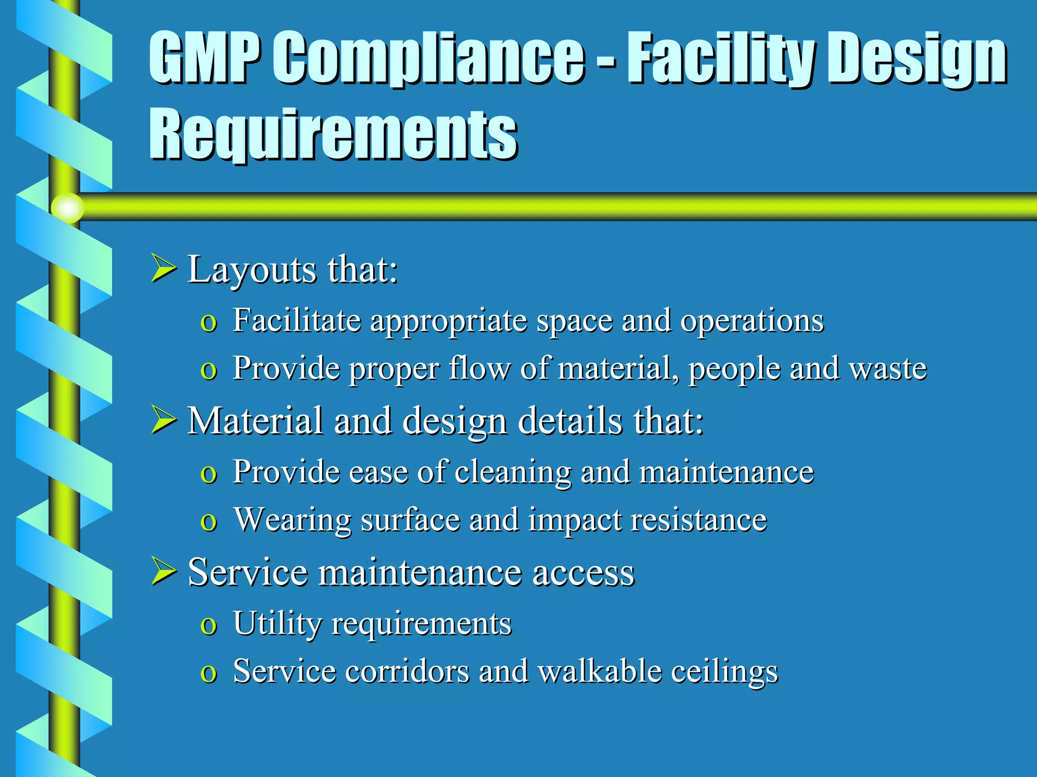
- Facility design must facilitate appropriate space, operations, material and waste flows to prevent contamination.
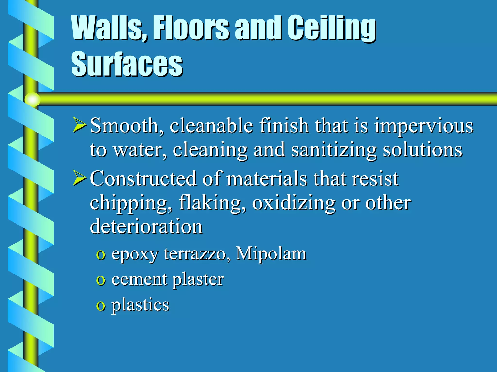
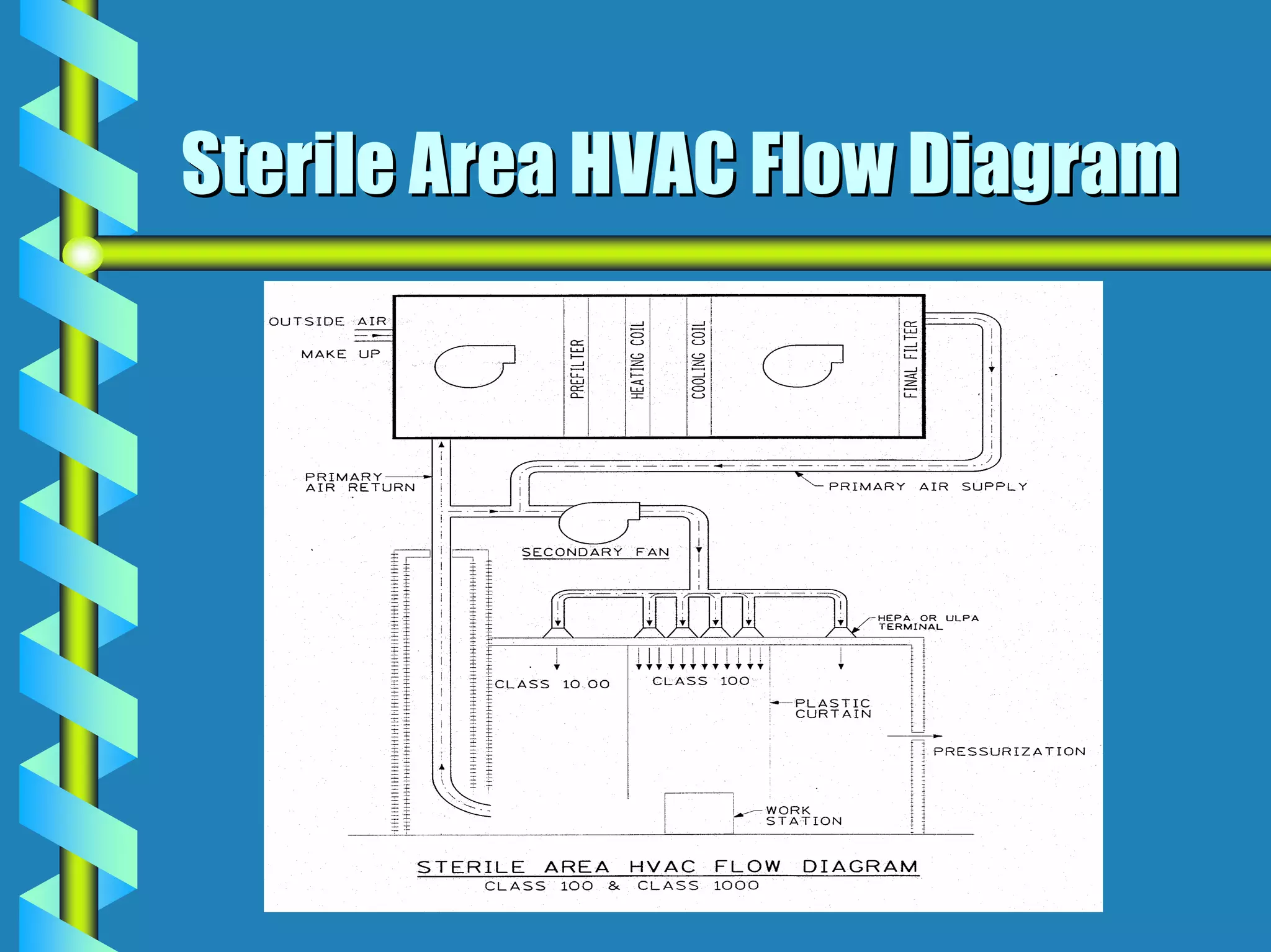
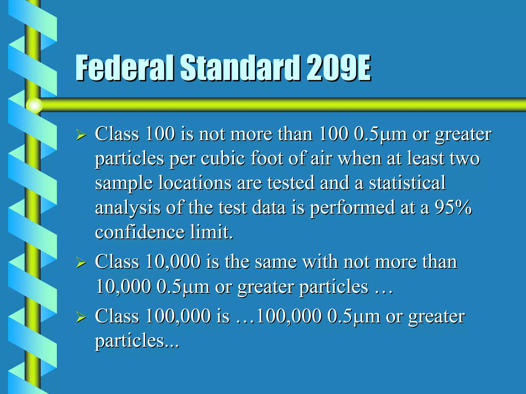
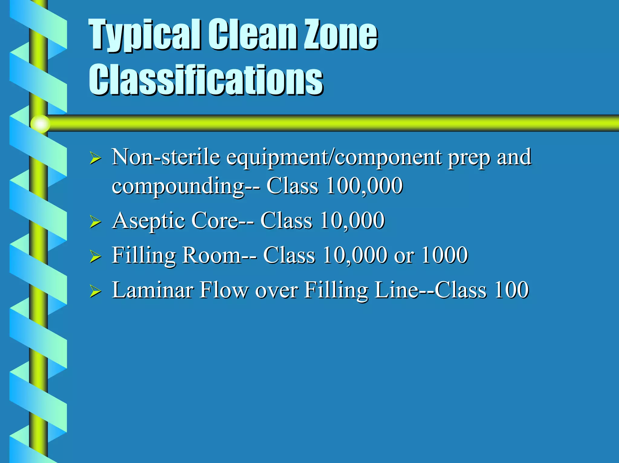
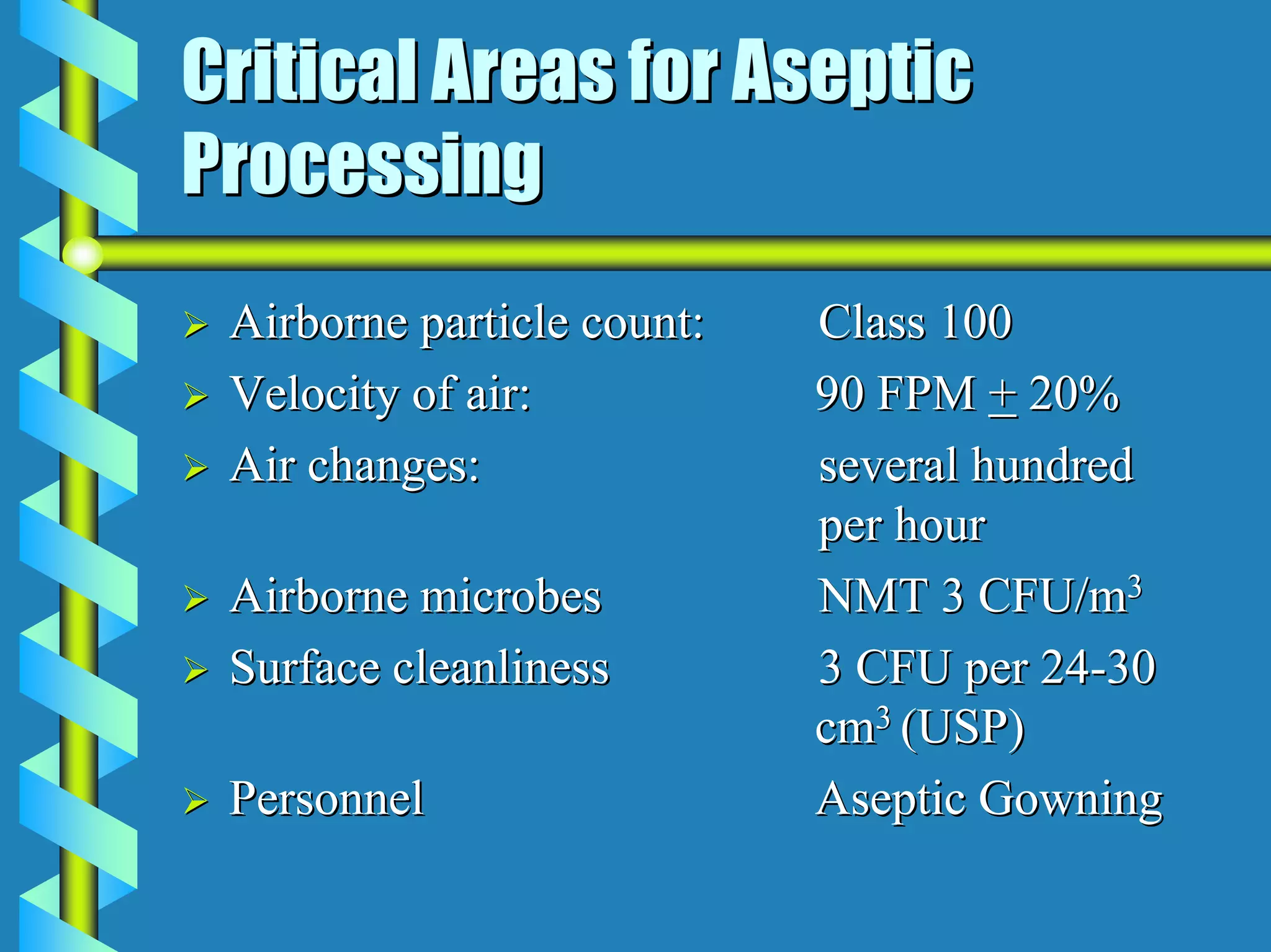
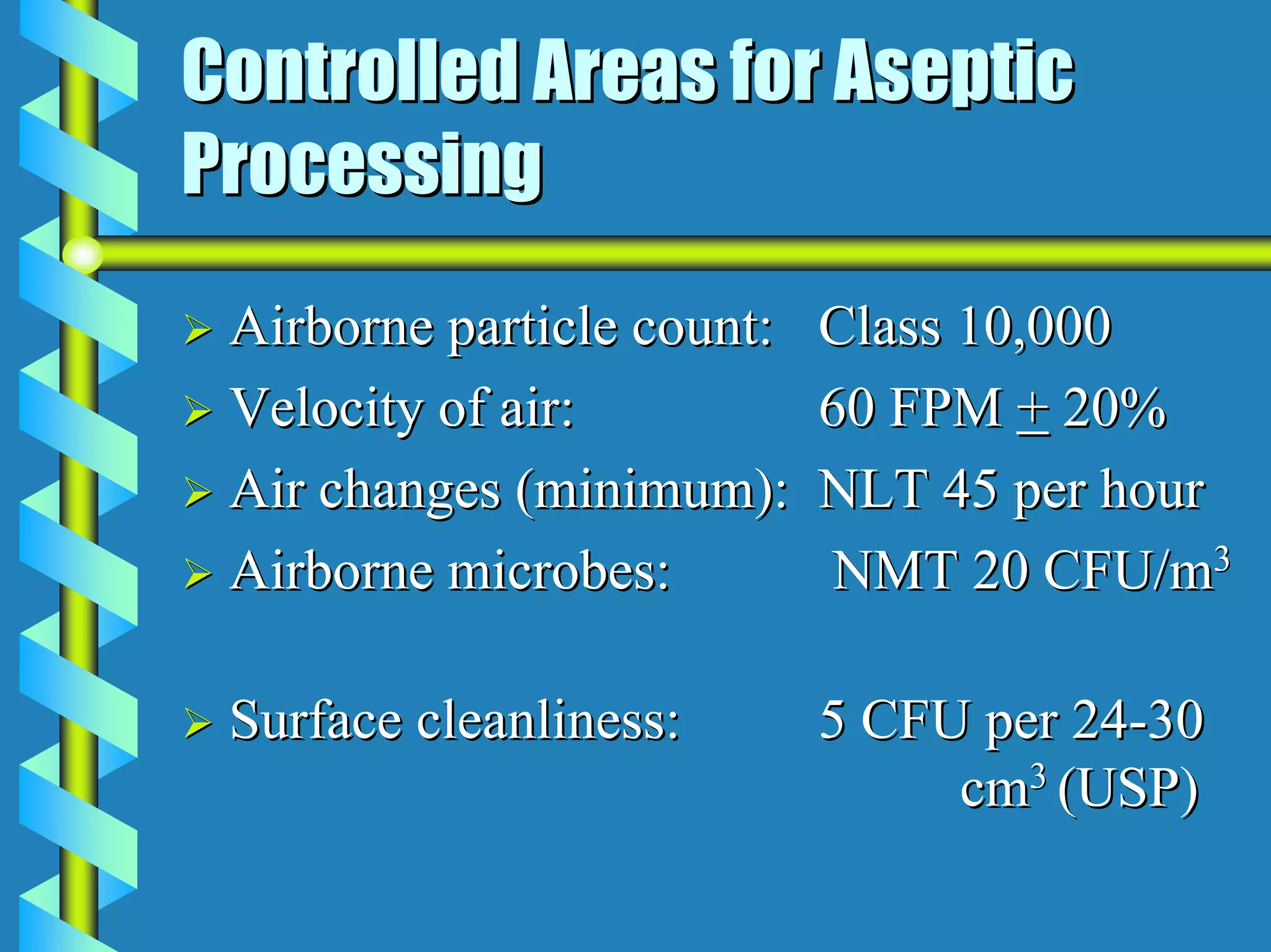
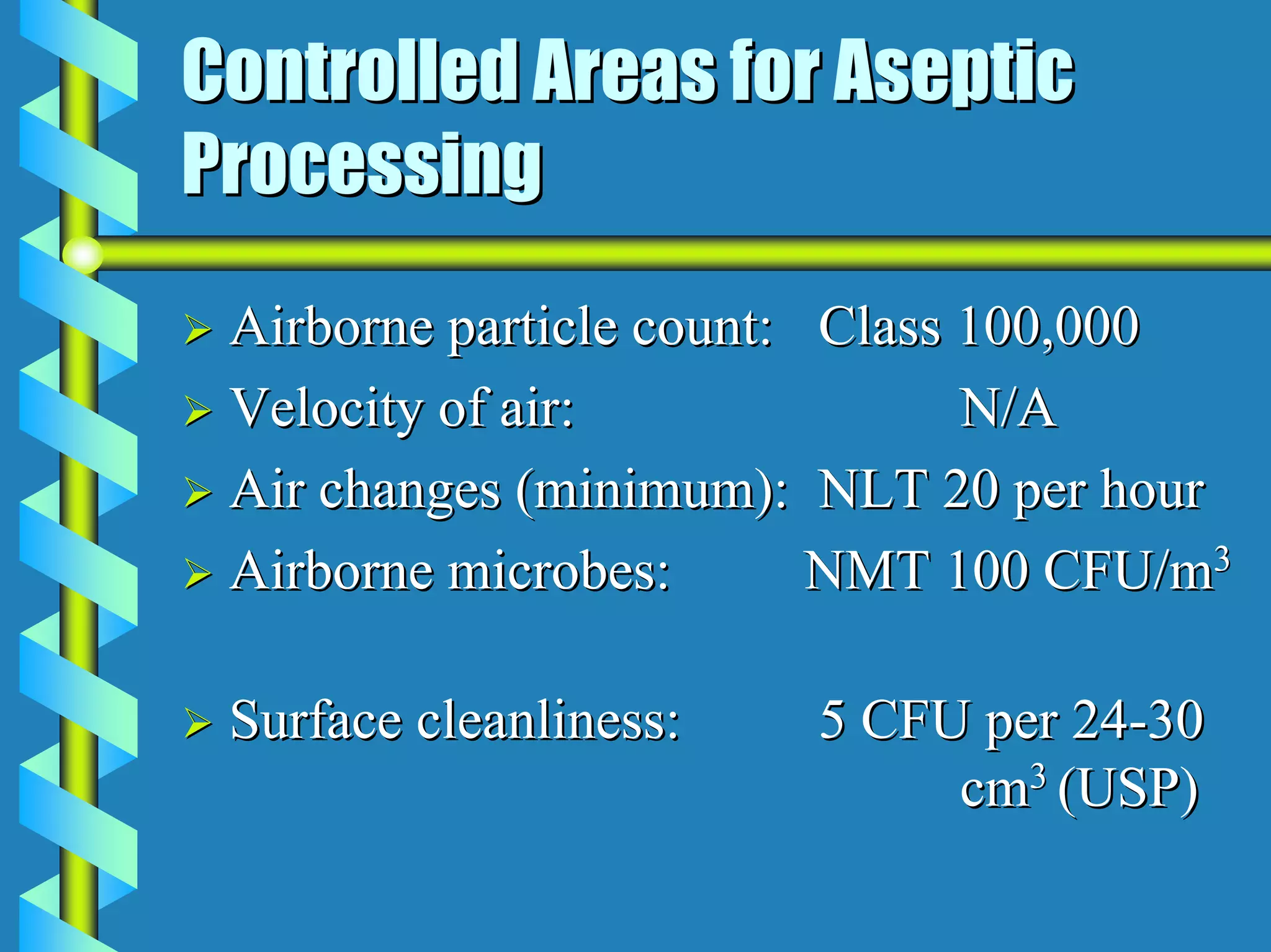
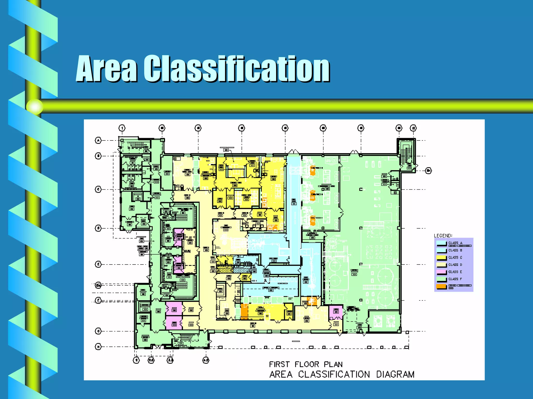
- Critical areas require stringent controls for airborne particles, air changes, airflow velocity, and surface cleanliness.
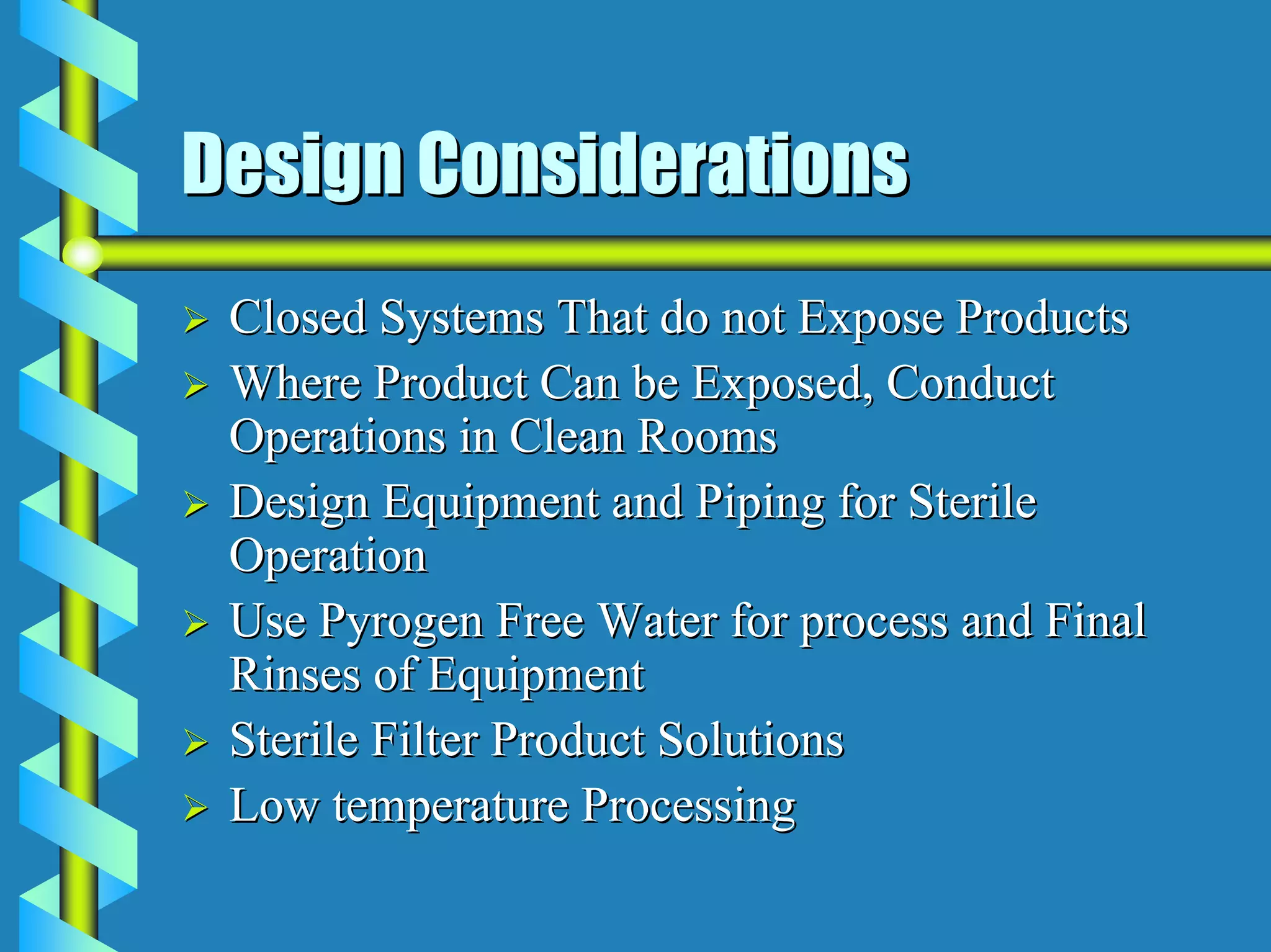
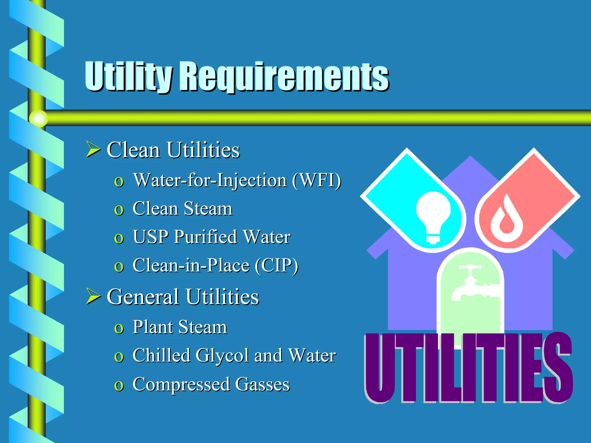
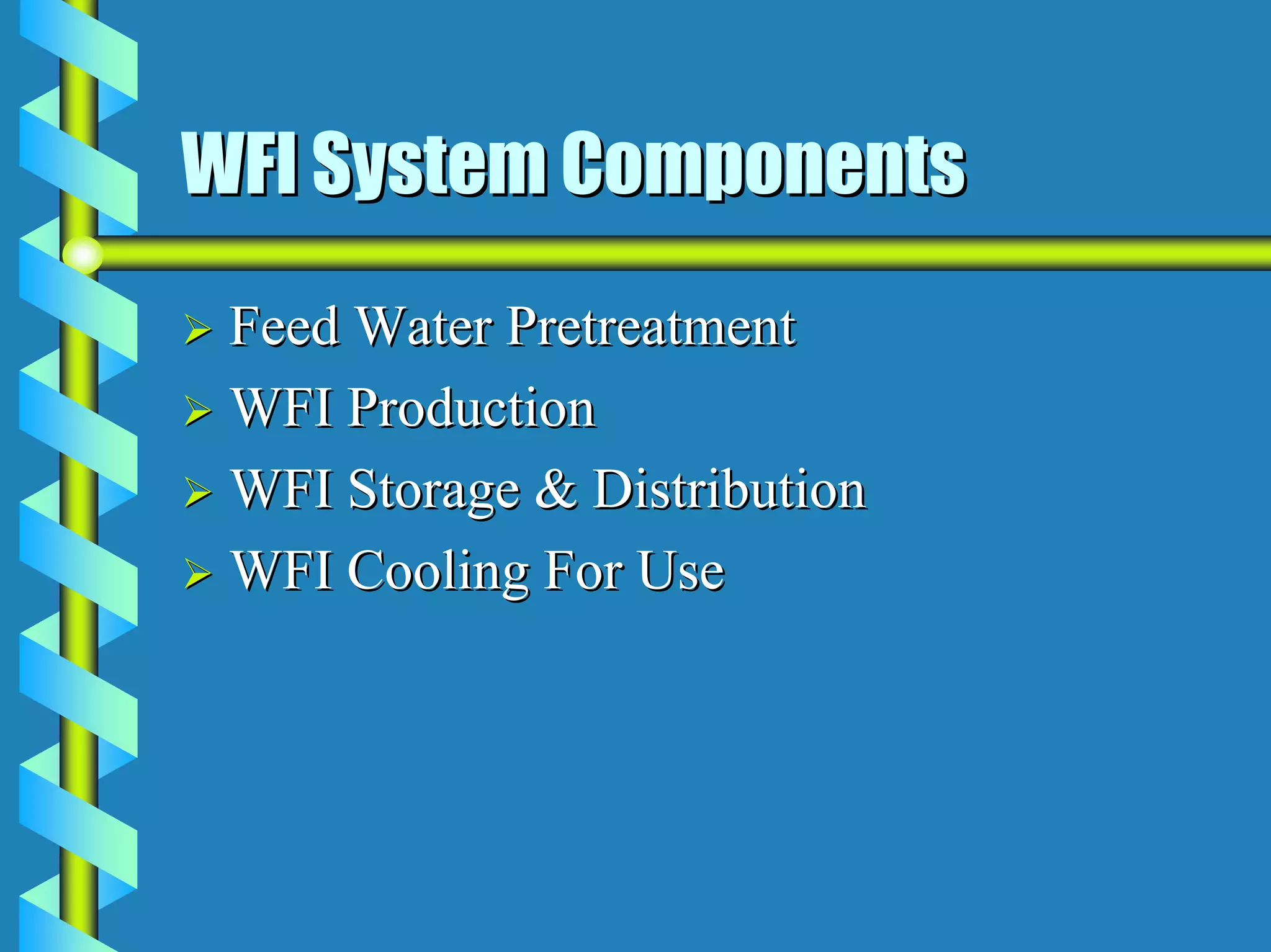
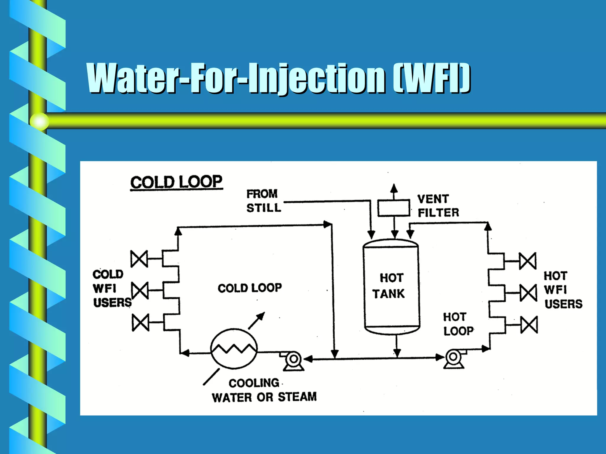
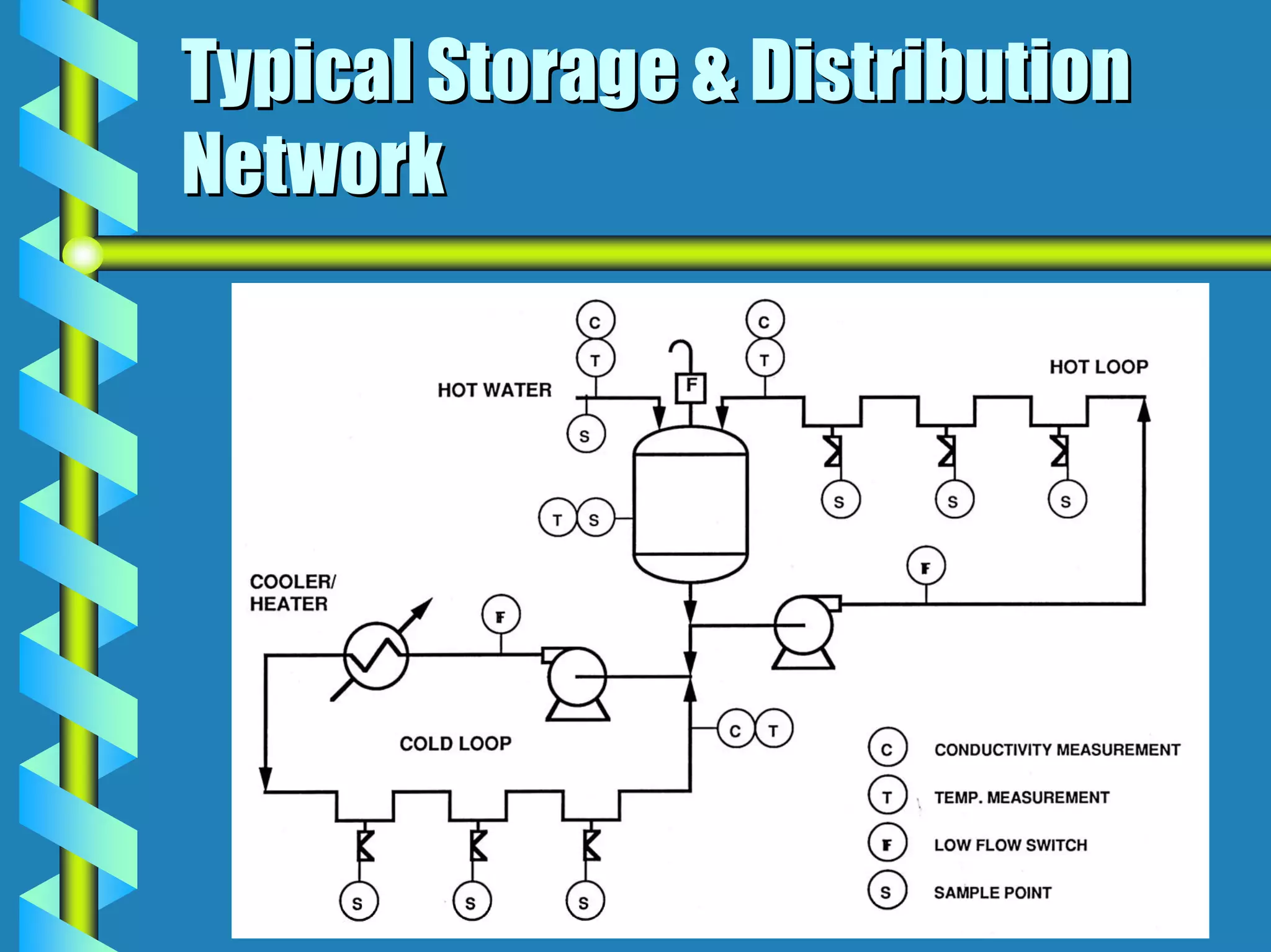
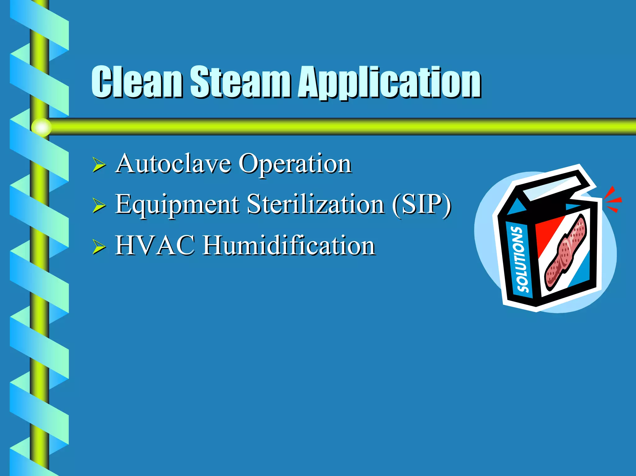
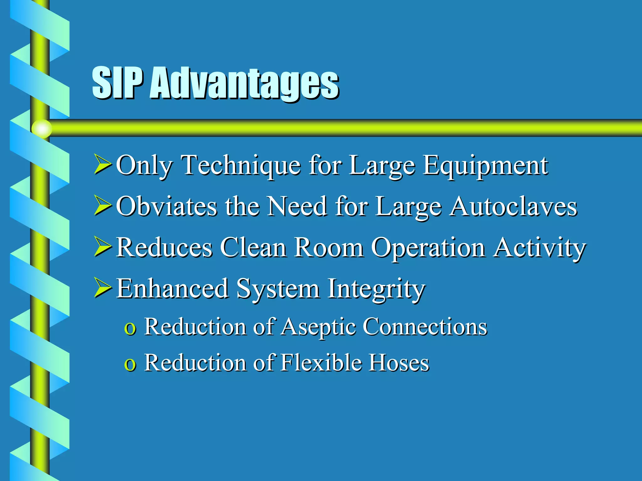
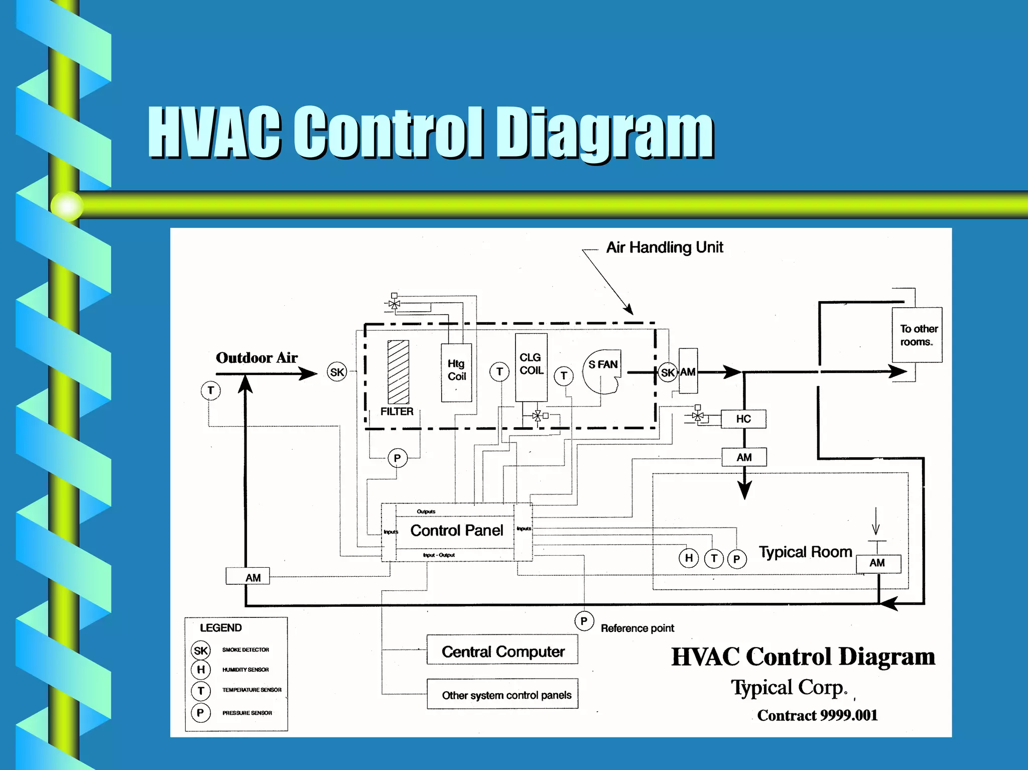
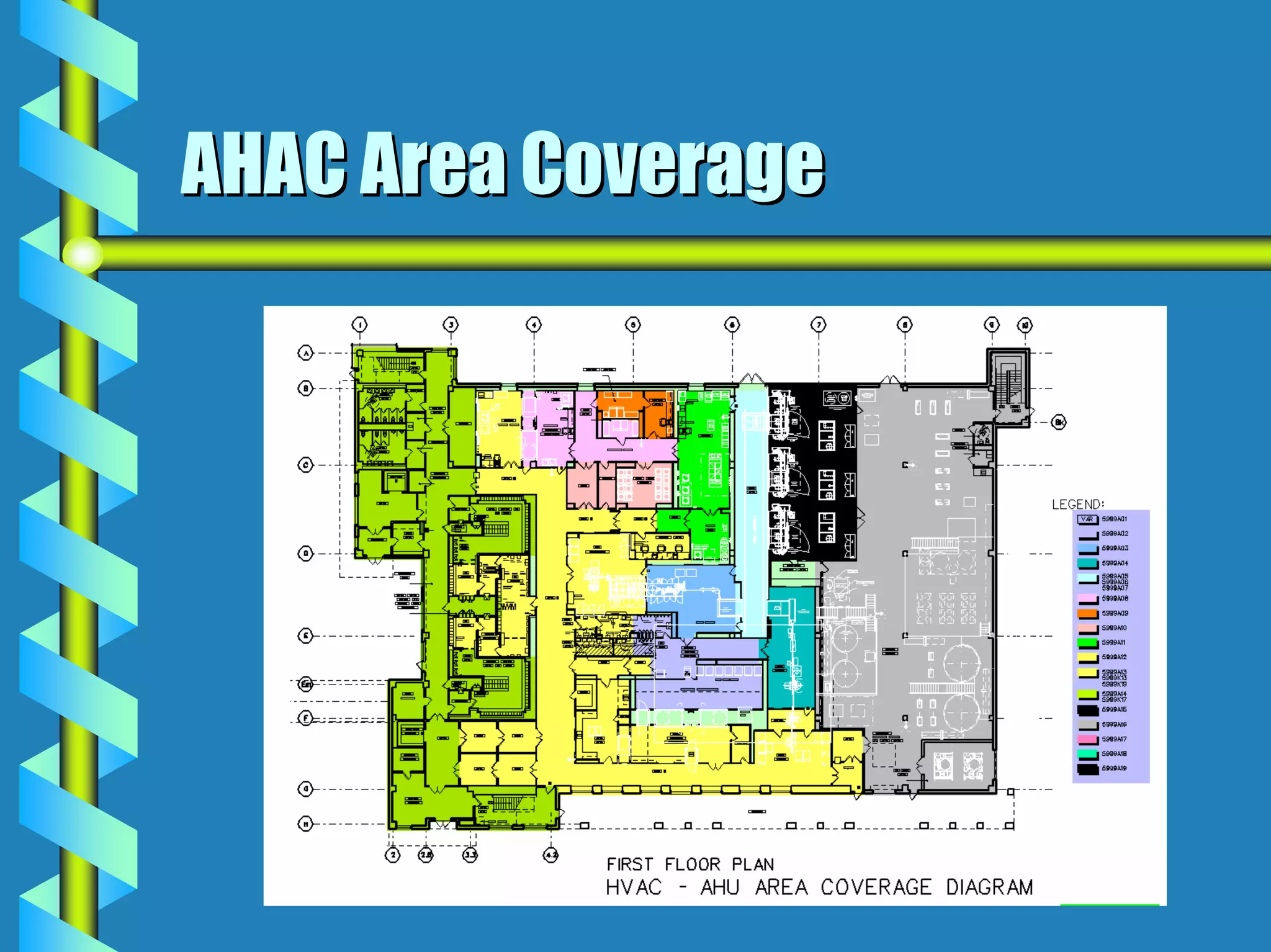
- Utilities like WFI, steam, and HVAC systems must be designed to stringent quality standards to prevent contamination.
- Documentation and validation are required to prove the facility is built as designed and certified for use.