Downloaded 766 times

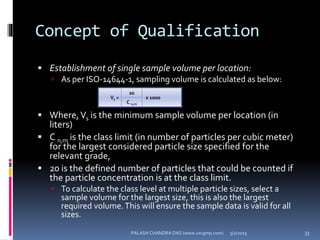


The document explains the critical role of HVAC systems in pharmaceutical facilities, emphasizing their importance in maintaining product quality, reliability, and operational efficiency. It details the design considerations unique to pharmaceutical HVAC systems, particularly for cleanroom environments, and outlines various design elements, operational features, and qualification processes necessary for compliance with regulatory standards. The document also discusses monitoring and maintenance protocols for ensuring optimal air quality and environmental controls.


