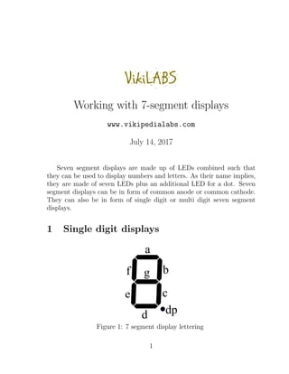
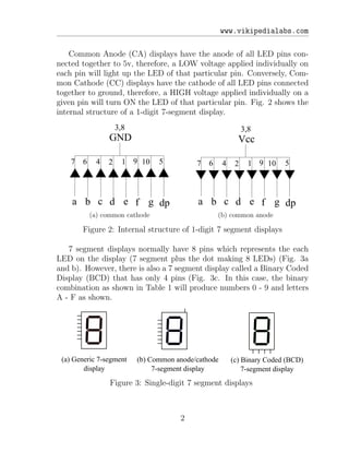
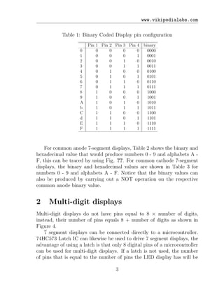
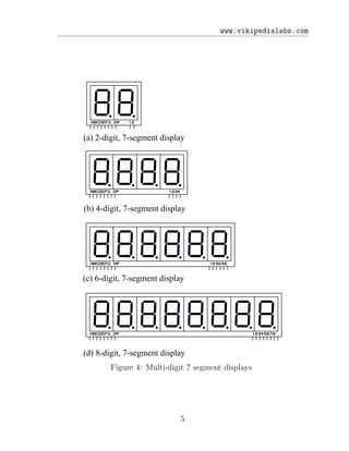
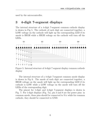
Seven segment displays use LEDs arranged in a pattern to display numbers and some letters. They are made up of 7 LED segments plus an optional decimal point LED. They can be configured as either common anode or common cathode. Multi-digit displays have additional pins to control each digit independently compared to single digit displays. A latch IC can be used to reduce the number of microcontroller pins needed to drive multi-digit seven segment displays.
1. VikiLABS
Working with 7-segment displays
www.vikipedialabs.com
July 14, 2017
Seven segment displays are made up of LEDs combined such that
they can be used to display numbers and letters. As their name implies,
they are made of seven LEDs plus an additional LED for a dot. Seven
segment displays can be in form of common anode or common cathode.
They can also be in form of single digit or multi digit seven segment
displays.
1 Single digit displays
b
a
c
d
e
f g
dp
Figure 1: 7 segment display lettering
1
2. www.vikipedialabs.com
Common Anode (CA) displays have the anode of all LED pins con-
nected together to 5v, therefore, a LOW voltage applied individually on
each pin will light up the LED of that particular pin. Conversely, Com-
mon Cathode (CC) displays have the cathode of all LED pins connected
together to ground, therefore, a HIGH voltage applied individually on a
given pin will turn ON the LED of that particular pin. Fig. 2 shows the
internal structure of a 1-digit 7-segment display.
a b c d e f g dp
GND
7 6 4 2 1 9 10 5
3,8
(a) common cathode
a b c d e f g dp
Vcc
7 6 4 2 1 9 10 5
3,8
(b) common anode
Figure 2: Internal structure of 1-digit 7 segment displays
7 segment displays normally have 8 pins which represents the each
LED on the display (7 segment plus the dot making 8 LEDs) (Fig. 3a
and b). However, there is also a 7 segment display called a Binary Coded
Display (BCD) that has only 4 pins (Fig. 3c. In this case, the binary
combination as shown in Table 1 will produce numbers 0 - 9 and letters
A - F as shown.
(a) Generic 7-segment
display
(b) Common anode/cathode
7-segment display
(c) Binary Coded (BCD)
7-segment display
Figure 3: Single-digit 7 segment displays
2
3. www.vikipedialabs.com
Table 1: Binary Coded Display pin configuration
Pin 1 Pin 2 Pin 3 Pin 4 binary
0 0 0 0 0 0000
1 0 0 0 1 0001
2 0 0 1 0 0010
3 0 0 1 1 0011
4 0 1 0 0 0100
5 0 1 0 1 0101
6 0 1 1 0 0110
7 0 1 1 1 0111
8 1 0 0 0 1000
9 1 0 0 1 1001
A 1 0 1 0 1010
b 1 0 1 1 1011
C 1 1 0 0 1100
d 1 1 0 1 1101
E 1 1 1 0 1110
F 1 1 1 1 1111
For common anode 7-segment displays, Table 2 shows the binary and
hexadecimal value that would produce numbers 0 - 9 and alphabets A -
F, this can be traced by using Fig. ??. For common cathode 7-segment
displays, the binary and hexadecimal values are shown in Table 3 for
numbers 0 - 9 and alphabets A - F. Notice that the binary values can
also be produced by carrying out a NOT operation on the respective
common anode binary value.
2 Multi-digit displays
Multi-digit displays do not have pins equal to 8 × number of digits,
instead, their number of pins equals 8 + number of digits as shown in
Figure 4.
7 segment displays can be connected directly to a microcontroller.
74HC573 Latch IC can likewise be used to drive 7 segment displays, the
advantage of using a latch is that only 8 digital pins of a microcontroller
can be used for multi-digit displays. If a latch is not used, the number
of pins that is equal to the number of pins the LED display has will be
3
6. www.vikipedialabs.com
used by the microcontroller.
3 4-digit 7-segment displays
The internal structure of a 4-digit 7-segment common cathode display
is shown in Fig 5. The cathode of each digit are connected together, a
LOW voltage on the cathode will light up the corresponding LED if its
anode is HIGH while a HIGH voltage on the cathode will turn off the
LEDs.
a b c d e f g dp
D1 D2 D3 D4
Figure 5: Internal structure of 4-digit 7 segment display common cathode
display
The internal structure of a 4-digit 7-segment common anode display
is shown in Fig 6. The anode of each digit are connected together, a
HIGH voltage on the anode will light up the corresponding LED if its
cathode is LOW while a LOW voltage on the anode will turn off the
LEDs of the corresponding digit.
The pinout for 1-digit and 4-digit 7-segment displays is shown in
Fig. 7. For 1-digit displays (Fig. 7a), pin 3 and 8 are the power pins: in
common anode, these pins should be connected to Vcc while for common
cathode, they should be connected to GND.
6
7. www.vikipedialabs.com
a b c d e f g dp
D1 D2 D3 D4
Figure 6: Internal structure of 4-digit 7 segment display common anode
display
(a) 1-digit display (b) 4-digit display
Figure 7: Pinout for 1-digit and 4-digit displays
7