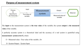
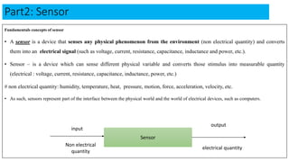
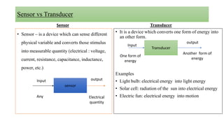
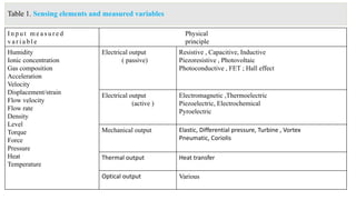
Mizan-Tepi University
College of Engineering And Technology
Department Of Electrical and Computer Engineering
• Course Title: Introduction to Instrumentation
Course Code: ECEG4169, ECTS Credits: 5
• Course Objectives & Competences to be acquired:
 To discuss the major elements of a measurement system.
 To discuss the principle of operation and behavior of typical sensing devices used in instrumentation.
Course Description / course contents:
1. General Principles of Measurement
2. Sensors and its Application
3. Signal Conditioning Circuits
4. Signal Conversion Elements
5. Output Presentation Devices/ or instruments
Part 1: General Principles of Measurement
1.1. Basic Concepts of Measurement
Measuring Instrument: It is an instrument used to measure an unknown quantity (measurand).
1.2. Performance Characteristics of Instrumentation / or Instrument: Static and Dynamic
i. Static Characteristics of Instrument: it is the set of criteria defined for the instruments, which are used to
measure: the quantities are slowly varying with time or mostly constant. i.e. do not vary with time.
1. Accuracy: It is defined as the degree of closeness with which the instrument reading approaches the true
value of the quantity to be measured. Or it is closeness to the truth value of the quantity.
Example: Assume that five reading was recorded by five different students for measuring 100 ohm resistor. True
vale = 100 ohm
Reading obtained: 101, 98, 100.5 , 101.3 and 99.2
From these five reading the value close to the true value is 100.5 ohm. Accuracy means conformity to truth.
2. Precision …...(continue )
• It is measure of the degree to which the successive measurements differ from each other. Or it is the
closeness among the successive measurement.
For example: suppose we want to measure 100ohm resistor. We take 5 reading as follows: 100.1, 100.1 , 99.7,
99.8 and 100. 2. From these reading, we observe that the reading are very close to each other. Thus we
conclude that if the difference between two successive measurement is very less, it is high precision.
If the difference between two successive measurement is very large, it is low precision.
There is the difference between accuracy and precision. Common example is when we have a target and an
arrow. Arrow which is thrown by an Archer on a target and we check the values are precise and accurate. See
on next slide.
Difference between precision and accuracy …..(continue)
• Assume that an Archer throw an arrow on a
disc and results as follows:
Target point disc
• Description:
A. high precision but not
accurate
B. Low precision and accurate
C. Less precision and less
accurate
D. High precision and high
accurate
a c
b d
3 . S e n s i t i v i t y
• Sensitivity defined as the smallest change in the input that can be measured by instrument.
• Or it is ability of an instrument which responds for any input change in measurement.
• Or smallest change in the measured variable to which the instrument responds. In general instruments are
sensitive for any change made in input variable.
• In formula form, it is the ratio of change in the output of an instrument to a change in the value of the quantity
to be measured. , if the ratio is very less the sensitivity of the instrument is high.
When the response or calibration curve of instrument is linear, sensitivity is defined as the slope of the
calibration curve.
Manufacturer defined sensitivity as ratio of input divided by output. i.e. inverse sensitivity or deflection factor =
change in input/change in output.
𝑆 =
∆𝑞𝑜
∆𝑞𝑖
ii. Dynamic Characteristics of Instrument:
• Dynamic char of instrument tell us the set of criteria defined for the instruments, which are changing with
time.
1. Speed of response
• It is defined as the rapidity within which a measurement system responds to changes in the measured
quantity. Or
• It shows how active or fast the instrument is.
2. Fidelity: It is defined as the degree of closeness with which the system indicates or records the signal which
is impressed upon it. Again it is defined as the ability of the system to reproduce output in the same way or
form as input.
Purpose of measurement system
The input to the measurement system is the true value of the variable; the system output is the measured
value of the variable.
A perfectly accurate system is a theoretical ideal and the accuracy of a real system is quantified using
measurement system error E, where
E = Measured value - True value of the variable , Or
E= System Output – System Input
Process
Or
Quantity to
be measured
Measurement
system
Output
Measured value of
variable
input
True value of
variable
Observer
Continue ….( purpose of measurement system )
Example:
1. If the True value of the resistor is 100 ohm and the measured value of it is 102 ohm, then
Error E = Measured value – true value = 102 ohm -100 ohm = 2 ohm.
2. If the measured value of the flow rate of gas in a pipe is 11.0 m3/h and the true value is 11.2 m3/h, then the
error E = Measured value – true value = -0.2 m3/h.
3. If the measured value of the rotational speed of an engine is 3140 rpm and the true value is 3133 rpm, then E =
Measured value – true value = +7 rpm. Error is the main performance indicator for a measurement system.
General structure of measurement system
The measurement system consists of several elements or blocks. It is possible to identify four types of element,
although in a given system one type of element may be missing or may occur more than once. The four types are
shown in Figure 1 and can be defined as follows.
Fig. 1 general Structures of Measurement system.
Sensing element
This is in contact with the process and gives an output which depends in some way on the variable to be measured. Examples are:
 Thermocouple: temp into millivolt
 Statin gauge: resistance depends on mechanical strain.
 Orifice plate: pressure drop depends on flow rate.
Sensing
Element
Signal
conditioning
Element
Signal
processing
Element
Data
Presentation
Element
Input
True
value
Output
Measured
value
Signal conditioning Element
• This takes the output of the sensing element and converts it into a form more suitable for further
processing, usually a d.c. voltage, d.c. current or frequency signal.
Examples are:
 Deflection bridge which converts an impedance change into a voltage change
 Amplifier which amplifies millivolts to volts
 Oscillator which converts an impedance change into a variable frequency voltage.
Signal processing Element
• This takes the output of the conditioning element and converts it into a form more suitable for presentation.
Examples are:
 Analogue-to-digital converter (ADC) which converts a voltage into a digital form for input to a computer
 Computer which calculates the measured value of the variable from the incoming digital data.
Data Presentation Element
• This presents the measured value in a form which can be easily recognized by the observer.
Examples are:
 Simple pointer–scale indicator
 Chart recorder
 Alphanumeric display
 Visual display unit (VDU).
Part2: Sensor
Fundamentals concepts of sensor
• A sensor is a device that senses any physical phenomenon from the environment (non electrical quantity) and converts
them into an electrical signal (such as voltage, current, resistance, capacitance, inductance and power, etc.).
• Sensor – is a device which can sense different physical variable and converts those stimulus into measurable quantity
(electrical : voltage, current, resistance, capacitance, inductance, power, etc.)
# non electrical quantity: humidity, temperature, heat, pressure, motion, force, acceleration, velocity, etc.
• As such, sensors represent part of the interface between the physical world and the world of electrical devices, such as computers.
Sensor
input
Non electrical
quantity
electrical quantity
output
Sensor vs Transducer
Sensor
• Sensor – is a device which can sense different
physical variable and converts those stimulus
into measurable quantity (electrical : voltage,
current, resistance, capacitance, inductance,
power, etc.)
Transducer
• It is a device which converts one form of energy into
an other form.
Examples
• Light bulb: electrical energy into light energy
• Solar cell: radiation of the sun into electrical energy
• Electric fun: electrical energy into motion
Transducer
Input
output
One form of
energy
Another form of
energy
sensor
Input
Any Electrical
quantity
output
Sensing elements
• Table 1 lists some sensing elements according to the physical principle involved, e.g. inductive or thermoelectric.
• The elements are classified according to whether the output signal is electrical, mechanical, thermal or optical.
Elements with an electrical output are further divided into passive and active.
Passive devices such as resistive, capacitive and inductive elements require an external power supply in order to
give a voltage or current output signal.
Active devices, e.g. electromagnetic and thermoelectric elements, need no external power supply.
Continue ….(sensing element)
• Sensors with a mechanical output are commonly used as the primary sensing element in measurement systems
for mechanical variables such as force or flow rate. In order to obtain an electrical signal, this primary element
is followed by a secondary sensing element with an electrical output signal. Examples are a resistive strain
gauge sensing the strain in an elastic cantilever in a force measurement system, and an electromagnetic
tachogenerator sensing the angular velocity of a turbine in a flow measurement system.
Table 1. Sensing elements and measured variables
I n p u t m e a s u r e d
v a r i a b l e
Physical
principle
Humidity
Ionic concentration
Gas composition
Acceleration
Velocity
Displacement/strain
Flow velocity
Flow rate
Density
Level
Torque
Force
Pressure
Heat
Temperature
Electrical output
( passive)
Resistive , Capacitive, Inductive
Piezoresistive , Photovoltaic
Photoconductive , FET ; Hall effect
Electrical output
(active )
Electromagnetic ,Thermoelectric
Piezoelectric, Electrochemical
Pyroelectric
Mechanical output Elastic, Differential pressure, Turbine , Vortex
Pneumatic, Coriolis
Thermal output Heat transfer
Optical output Various
Temperature measurement
• Temperature (temp) is the degree of hotness or coldness of a body.
temp : the degree of hotness
heat: the quality of hotness
Temp SI units: degree celiceus ,degree Fahrenheit
kelvin: 𝐾 = T °C + 273
Methods of Temperature measurement
1) Non electrical type temp measurement
2) Electrical type temperature measurement
3) Radiation type temperature measurement
I ) RTD (Resistance temperature Detector)
Change in resistance caused by change in its temp.
RTD has +ve temp coefficient resistance.
PRTD : can be used over a wide temperature range (-200 to
+800 °C) , P stands for Platinum
Temp = Resistance i.e. As T increase R increase
Mathematical expression of r/ship between(b/n) temp and
resistance of RTD given as:
𝑅𝑇 = 𝑅0 1 + α𝑇 + β𝑇2
+ γ𝑇3
+ ⋯ ;
where RT = resistance at final temp (Ω ),
𝑅0 = resistance at 0 °C (Ω )
α, β 𝑎𝑛𝑑 γ = temp coefficient of resistance (/°C )
• Platinum is preferred because it is chemically
inert, has linear and repeatable resistance/
temperature characteristics.
Fig2. R vs Temp for RTD
The magnitude of the non-linear terms is usually
small. 𝑅𝑇2 = 𝑅𝑇1 (1 + α𝑇), where
T1= initial temp and T2 = final temp
Temp (°C )
ii) Thermistor (Thermal Resistors)
• Thermistor is made up of semiconductor materials.
• It is used to measure low temperature up to 15 °C – 60°C.
• It has negative temp coefficient (NTC) of resistance - in a highly non-linear way.
Temp = resistance
Thermistor: T α
1
𝑅
i.e. As T increase R decrease and vice versa
A resistance temp r/ship for a thermistor is given by Fig3. R vs T for Thermistor
𝑅𝑇2 = 𝑅𝑇1 𝐸𝑥𝑝β(
1
𝑇2
−
1
𝑇1
); Where 𝑅𝑇1 (Ω) is the resistance at reference temperature T1 (in K), usually T1 =
25 °C = 298 K ; β is constant for the thermistor in (K)
Temp T (°C )
iii) Thermoelectric Sensor
• Thermo-couple
• It is a kind of temperature sensor that is
used to measure the temperature at one
specific point in the form of the EMF or an
Electric current.
• A thermocouple can measure a wide range
of temperatures.
• It is a simple, robust and cost - effective
temperature sensor used in various
industrial application.
• Working Principle of Thermocouple
• When two wires of dissimilar (or different) metals are joined
at both ends, two bimetallic junctions (jun) are formed. One
jun is heated using heater & other jun is Immersed in water.
When a multimeter is connected in the ckt, we observe that
multimeter giving some reading. This is the vol b/n the hot and
cold junction. Now, if we increase the temp of hot jun using
heater the reading on the multimeter also increases. This
follows that, the vol b/n this two junctions (jun) is the function
of temperature d/ce b/n them.
Cold
junction
Hot
junction
Multimeter
Thermo-couple ,,,,,,,continue
• Working Principle of Thermocouple
• When two wires of dissimilar (or different) metals (A and B) are joined at both ends, two
bimetallic junctions are formed. One junction (jun) is heated using heater & other jun is
immersed in water.
When a multimeter is connected in the ckt, we observe that multimeter giving some reading
(in mv level). This is the vol b/n the hot and cold junction. Now, if we increase the temp of hot
jun using heater the reading on the multimeter also increases. This follows that, the vol b/n
this two juns is the function of temperature d/ce b/n them. This effect is known as seebeck
effect.
Hot
junction Cold
junction
Multimeter
A
B
Part 3: Signal Conditioning Element
• It consists of
(i) Deflection Bridges; (ii) Amplifier ; (iii) Attenuator
Deflection Bridges: They are used to convert the output of resistive, capacitive and inductive sensors into
a voltage signal.
 From the output of different sensors the bridge can gets input (mechanical input) and then give out / or
measure the electrical quantity in terms of voltages.
Where D – deflection shows zero reading when the ckt is balanced.
Part 3: Signal Conditioning Element ,,,,,,,contiune
ii) Amplifier: it is a device which strengthen the input signal at
its output sides. In simple word it can amplify the amplitude of
input signal applied in a given system.
• Example IC 741 – Operational Amplifier (OPAMP) it has 8
pins.
• It can acts as inverting , non inverting , summing, difference,
differential and Integral Amplifier based on the input
element applied on its terminals and external elements
configure for operation.
• Amplifiers are necessary in order to amplify low-level
signals, e.g. thermocouple or strain gauge bridge output
voltages, to a level which enables them to be further
processed.
•
Part 3: Signal Conditioning Element ,,,,,,,contiune
• Attenuator: the term attenuator means to “ reduce the size.”
• The purpose of attenuator is to reduce the amplitude of input signal. If the vertical input signal is high,
then attenuated before applying it to the vertical amplifier.
• Most of the attenuator circuit are simple resistive voltage divider circuit.
• Attenuator factor is the reciprocal of voltage divider ratio (
𝑉𝑂
𝑉𝑖
=
𝑅
𝑅𝑡
). Where Rt = total Resistance , R =
total resistance from divider attenuator terminal to ground.
Part 4: Signal processing Element
• Digital-to-analogue converters (DACs)
• Analogue-to-digital converters (ADCs)
• Need of ADC and DAC: To connect one form of signal with other circuit capable of processing other type data it
becomes essential to use the above converters. For example: ADC is used to convert an analog signal from
transducers measuring temp, pressure, etc. into an equivalent digital signals. Similarly if analog output signal is
required in some application, digital to analog converter (DAC) is used.
Signal processing Element…..continue
Analog to Digital Converters (ADC)
•The method of converting an analog voltage into an equivalent digital numbers is known as analog to digital conversion.
The circuit used for this purpose is called as ADC.
•There are different methods for digitizing analog signals.
1)simultaneous A/D converter
2)Counter type A/D converter
3)Successive approximation type A/D converter
4)Dual slope A/D converter
Last three techniques compare input analog voltage with digital counter signal(in analog form) and allows counter to
increment till it reaches to input signal.
Digital to Analog Converters (DAC)
• The process of converting a digital data into an equivalent analog signal is known as digital to analog
conversion and ckt that converts data is known as DAC. The converter ckt input is a bit parallel such as 3bit, 4
bit, 8 bit, 16 bit etc., each bit is either 0 or 1.
• Two methods of digital to analog conversion
i) weighted- resistor D/A converter
ii) R-2R ladder D/A converter
In both the methods each bit is connected to either 0 or 1 by using separate switches.
The output voltage of a D/A converter is made proportional to the equivalent binary weighed.
i) binary weighted- resistor network D/A converter
Fig a. 8 bit weighted resistor n/w DAC with Summing
amplifier
• Switch status: 1 closed
• Switch status: o open
• Each bit signal is connected with weighted resistor.
MSB LSB
• The MSB input is connected with lowest resistor and
towards LSB the resistance value is made twice of previous
resistor.
• The purpose of increasing the resistor value is to pass
minimum current through LSB resistance while maximum
current through MSB resistance. The n/w connected in
this method (Fig a.) is also known as variable – resistor
n/w.
• The ckt diagram of this D/A converter is Summing
amplifier with 8 bit digital inputs b0- b7. b7 is MSB and
weightage resistor of “R” , while bo is LSB with weightage
resistor of 128R.
• The i/p to the ckt can be connected by using 8 switches so
that each switch can be either at 0 level or l level. The o/p
vol of the D/A converter is given by
• Vo =
Digital to Analog Converters (DAC) ,,,, continue
• For example, consider a 3 bit D/A converter as shown infig1 below.
It has analog output and each output is different and equivalent to its
binary input.
Examples presented in separate sheet( done in class)
D/A
Converter
20
21
22
output

Introduction to Instrumentation p point presentation.pptx

  • 1.
    Mizan-Tepi University College ofEngineering And Technology Department Of Electrical and Computer Engineering • Course Title: Introduction to Instrumentation Course Code: ECEG4169, ECTS Credits: 5 • Course Objectives & Competences to be acquired:  To discuss the major elements of a measurement system.  To discuss the principle of operation and behavior of typical sensing devices used in instrumentation.
  • 2.
    Course Description /course contents: 1. General Principles of Measurement 2. Sensors and its Application 3. Signal Conditioning Circuits 4. Signal Conversion Elements 5. Output Presentation Devices/ or instruments
  • 3.
    Part 1: GeneralPrinciples of Measurement 1.1. Basic Concepts of Measurement Measuring Instrument: It is an instrument used to measure an unknown quantity (measurand). 1.2. Performance Characteristics of Instrumentation / or Instrument: Static and Dynamic i. Static Characteristics of Instrument: it is the set of criteria defined for the instruments, which are used to measure: the quantities are slowly varying with time or mostly constant. i.e. do not vary with time. 1. Accuracy: It is defined as the degree of closeness with which the instrument reading approaches the true value of the quantity to be measured. Or it is closeness to the truth value of the quantity. Example: Assume that five reading was recorded by five different students for measuring 100 ohm resistor. True vale = 100 ohm Reading obtained: 101, 98, 100.5 , 101.3 and 99.2 From these five reading the value close to the true value is 100.5 ohm. Accuracy means conformity to truth.
  • 4.
    2. Precision …...(continue) • It is measure of the degree to which the successive measurements differ from each other. Or it is the closeness among the successive measurement. For example: suppose we want to measure 100ohm resistor. We take 5 reading as follows: 100.1, 100.1 , 99.7, 99.8 and 100. 2. From these reading, we observe that the reading are very close to each other. Thus we conclude that if the difference between two successive measurement is very less, it is high precision. If the difference between two successive measurement is very large, it is low precision. There is the difference between accuracy and precision. Common example is when we have a target and an arrow. Arrow which is thrown by an Archer on a target and we check the values are precise and accurate. See on next slide.
  • 5.
    Difference between precisionand accuracy …..(continue) • Assume that an Archer throw an arrow on a disc and results as follows: Target point disc • Description: A. high precision but not accurate B. Low precision and accurate C. Less precision and less accurate D. High precision and high accurate a c b d
  • 6.
    3 . Se n s i t i v i t y • Sensitivity defined as the smallest change in the input that can be measured by instrument. • Or it is ability of an instrument which responds for any input change in measurement. • Or smallest change in the measured variable to which the instrument responds. In general instruments are sensitive for any change made in input variable. • In formula form, it is the ratio of change in the output of an instrument to a change in the value of the quantity to be measured. , if the ratio is very less the sensitivity of the instrument is high. When the response or calibration curve of instrument is linear, sensitivity is defined as the slope of the calibration curve. Manufacturer defined sensitivity as ratio of input divided by output. i.e. inverse sensitivity or deflection factor = change in input/change in output. 𝑆 = ∆𝑞𝑜 ∆𝑞𝑖
  • 7.
    ii. Dynamic Characteristicsof Instrument: • Dynamic char of instrument tell us the set of criteria defined for the instruments, which are changing with time. 1. Speed of response • It is defined as the rapidity within which a measurement system responds to changes in the measured quantity. Or • It shows how active or fast the instrument is. 2. Fidelity: It is defined as the degree of closeness with which the system indicates or records the signal which is impressed upon it. Again it is defined as the ability of the system to reproduce output in the same way or form as input.
  • 8.
    Purpose of measurementsystem The input to the measurement system is the true value of the variable; the system output is the measured value of the variable. A perfectly accurate system is a theoretical ideal and the accuracy of a real system is quantified using measurement system error E, where E = Measured value - True value of the variable , Or E= System Output – System Input Process Or Quantity to be measured Measurement system Output Measured value of variable input True value of variable Observer
  • 9.
    Continue ….( purposeof measurement system ) Example: 1. If the True value of the resistor is 100 ohm and the measured value of it is 102 ohm, then Error E = Measured value – true value = 102 ohm -100 ohm = 2 ohm. 2. If the measured value of the flow rate of gas in a pipe is 11.0 m3/h and the true value is 11.2 m3/h, then the error E = Measured value – true value = -0.2 m3/h. 3. If the measured value of the rotational speed of an engine is 3140 rpm and the true value is 3133 rpm, then E = Measured value – true value = +7 rpm. Error is the main performance indicator for a measurement system.
  • 10.
    General structure ofmeasurement system The measurement system consists of several elements or blocks. It is possible to identify four types of element, although in a given system one type of element may be missing or may occur more than once. The four types are shown in Figure 1 and can be defined as follows. Fig. 1 general Structures of Measurement system. Sensing element This is in contact with the process and gives an output which depends in some way on the variable to be measured. Examples are:  Thermocouple: temp into millivolt  Statin gauge: resistance depends on mechanical strain.  Orifice plate: pressure drop depends on flow rate. Sensing Element Signal conditioning Element Signal processing Element Data Presentation Element Input True value Output Measured value
  • 11.
    Signal conditioning Element •This takes the output of the sensing element and converts it into a form more suitable for further processing, usually a d.c. voltage, d.c. current or frequency signal. Examples are:  Deflection bridge which converts an impedance change into a voltage change  Amplifier which amplifies millivolts to volts  Oscillator which converts an impedance change into a variable frequency voltage.
  • 12.
    Signal processing Element •This takes the output of the conditioning element and converts it into a form more suitable for presentation. Examples are:  Analogue-to-digital converter (ADC) which converts a voltage into a digital form for input to a computer  Computer which calculates the measured value of the variable from the incoming digital data.
  • 13.
    Data Presentation Element •This presents the measured value in a form which can be easily recognized by the observer. Examples are:  Simple pointer–scale indicator  Chart recorder  Alphanumeric display  Visual display unit (VDU).
  • 14.
    Part2: Sensor Fundamentals conceptsof sensor • A sensor is a device that senses any physical phenomenon from the environment (non electrical quantity) and converts them into an electrical signal (such as voltage, current, resistance, capacitance, inductance and power, etc.). • Sensor – is a device which can sense different physical variable and converts those stimulus into measurable quantity (electrical : voltage, current, resistance, capacitance, inductance, power, etc.) # non electrical quantity: humidity, temperature, heat, pressure, motion, force, acceleration, velocity, etc. • As such, sensors represent part of the interface between the physical world and the world of electrical devices, such as computers. Sensor input Non electrical quantity electrical quantity output
  • 15.
    Sensor vs Transducer Sensor •Sensor – is a device which can sense different physical variable and converts those stimulus into measurable quantity (electrical : voltage, current, resistance, capacitance, inductance, power, etc.) Transducer • It is a device which converts one form of energy into an other form. Examples • Light bulb: electrical energy into light energy • Solar cell: radiation of the sun into electrical energy • Electric fun: electrical energy into motion Transducer Input output One form of energy Another form of energy sensor Input Any Electrical quantity output
  • 16.
    Sensing elements • Table1 lists some sensing elements according to the physical principle involved, e.g. inductive or thermoelectric. • The elements are classified according to whether the output signal is electrical, mechanical, thermal or optical. Elements with an electrical output are further divided into passive and active. Passive devices such as resistive, capacitive and inductive elements require an external power supply in order to give a voltage or current output signal. Active devices, e.g. electromagnetic and thermoelectric elements, need no external power supply.
  • 17.
    Continue ….(sensing element) •Sensors with a mechanical output are commonly used as the primary sensing element in measurement systems for mechanical variables such as force or flow rate. In order to obtain an electrical signal, this primary element is followed by a secondary sensing element with an electrical output signal. Examples are a resistive strain gauge sensing the strain in an elastic cantilever in a force measurement system, and an electromagnetic tachogenerator sensing the angular velocity of a turbine in a flow measurement system.
  • 18.
    Table 1. Sensingelements and measured variables I n p u t m e a s u r e d v a r i a b l e Physical principle Humidity Ionic concentration Gas composition Acceleration Velocity Displacement/strain Flow velocity Flow rate Density Level Torque Force Pressure Heat Temperature Electrical output ( passive) Resistive , Capacitive, Inductive Piezoresistive , Photovoltaic Photoconductive , FET ; Hall effect Electrical output (active ) Electromagnetic ,Thermoelectric Piezoelectric, Electrochemical Pyroelectric Mechanical output Elastic, Differential pressure, Turbine , Vortex Pneumatic, Coriolis Thermal output Heat transfer Optical output Various
  • 19.
    Temperature measurement • Temperature(temp) is the degree of hotness or coldness of a body. temp : the degree of hotness heat: the quality of hotness Temp SI units: degree celiceus ,degree Fahrenheit kelvin: 𝐾 = T °C + 273 Methods of Temperature measurement 1) Non electrical type temp measurement 2) Electrical type temperature measurement 3) Radiation type temperature measurement
  • 20.
    I ) RTD(Resistance temperature Detector) Change in resistance caused by change in its temp. RTD has +ve temp coefficient resistance. PRTD : can be used over a wide temperature range (-200 to +800 °C) , P stands for Platinum Temp = Resistance i.e. As T increase R increase Mathematical expression of r/ship between(b/n) temp and resistance of RTD given as: 𝑅𝑇 = 𝑅0 1 + α𝑇 + β𝑇2 + γ𝑇3 + ⋯ ; where RT = resistance at final temp (Ω ), 𝑅0 = resistance at 0 °C (Ω ) α, β 𝑎𝑛𝑑 γ = temp coefficient of resistance (/°C ) • Platinum is preferred because it is chemically inert, has linear and repeatable resistance/ temperature characteristics. Fig2. R vs Temp for RTD The magnitude of the non-linear terms is usually small. 𝑅𝑇2 = 𝑅𝑇1 (1 + α𝑇), where T1= initial temp and T2 = final temp Temp (°C )
  • 21.
    ii) Thermistor (ThermalResistors) • Thermistor is made up of semiconductor materials. • It is used to measure low temperature up to 15 °C – 60°C. • It has negative temp coefficient (NTC) of resistance - in a highly non-linear way. Temp = resistance Thermistor: T α 1 𝑅 i.e. As T increase R decrease and vice versa A resistance temp r/ship for a thermistor is given by Fig3. R vs T for Thermistor 𝑅𝑇2 = 𝑅𝑇1 𝐸𝑥𝑝β( 1 𝑇2 − 1 𝑇1 ); Where 𝑅𝑇1 (Ω) is the resistance at reference temperature T1 (in K), usually T1 = 25 °C = 298 K ; β is constant for the thermistor in (K) Temp T (°C )
  • 22.
    iii) Thermoelectric Sensor •Thermo-couple • It is a kind of temperature sensor that is used to measure the temperature at one specific point in the form of the EMF or an Electric current. • A thermocouple can measure a wide range of temperatures. • It is a simple, robust and cost - effective temperature sensor used in various industrial application. • Working Principle of Thermocouple • When two wires of dissimilar (or different) metals are joined at both ends, two bimetallic junctions (jun) are formed. One jun is heated using heater & other jun is Immersed in water. When a multimeter is connected in the ckt, we observe that multimeter giving some reading. This is the vol b/n the hot and cold junction. Now, if we increase the temp of hot jun using heater the reading on the multimeter also increases. This follows that, the vol b/n this two junctions (jun) is the function of temperature d/ce b/n them. Cold junction Hot junction Multimeter
  • 23.
    Thermo-couple ,,,,,,,continue • WorkingPrinciple of Thermocouple • When two wires of dissimilar (or different) metals (A and B) are joined at both ends, two bimetallic junctions are formed. One junction (jun) is heated using heater & other jun is immersed in water. When a multimeter is connected in the ckt, we observe that multimeter giving some reading (in mv level). This is the vol b/n the hot and cold junction. Now, if we increase the temp of hot jun using heater the reading on the multimeter also increases. This follows that, the vol b/n this two juns is the function of temperature d/ce b/n them. This effect is known as seebeck effect. Hot junction Cold junction Multimeter A B
  • 24.
    Part 3: SignalConditioning Element • It consists of (i) Deflection Bridges; (ii) Amplifier ; (iii) Attenuator Deflection Bridges: They are used to convert the output of resistive, capacitive and inductive sensors into a voltage signal.  From the output of different sensors the bridge can gets input (mechanical input) and then give out / or measure the electrical quantity in terms of voltages. Where D – deflection shows zero reading when the ckt is balanced.
  • 25.
    Part 3: SignalConditioning Element ,,,,,,,contiune ii) Amplifier: it is a device which strengthen the input signal at its output sides. In simple word it can amplify the amplitude of input signal applied in a given system. • Example IC 741 – Operational Amplifier (OPAMP) it has 8 pins. • It can acts as inverting , non inverting , summing, difference, differential and Integral Amplifier based on the input element applied on its terminals and external elements configure for operation. • Amplifiers are necessary in order to amplify low-level signals, e.g. thermocouple or strain gauge bridge output voltages, to a level which enables them to be further processed. •
  • 26.
    Part 3: SignalConditioning Element ,,,,,,,contiune • Attenuator: the term attenuator means to “ reduce the size.” • The purpose of attenuator is to reduce the amplitude of input signal. If the vertical input signal is high, then attenuated before applying it to the vertical amplifier. • Most of the attenuator circuit are simple resistive voltage divider circuit. • Attenuator factor is the reciprocal of voltage divider ratio ( 𝑉𝑂 𝑉𝑖 = 𝑅 𝑅𝑡 ). Where Rt = total Resistance , R = total resistance from divider attenuator terminal to ground.
  • 27.
    Part 4: Signalprocessing Element • Digital-to-analogue converters (DACs) • Analogue-to-digital converters (ADCs) • Need of ADC and DAC: To connect one form of signal with other circuit capable of processing other type data it becomes essential to use the above converters. For example: ADC is used to convert an analog signal from transducers measuring temp, pressure, etc. into an equivalent digital signals. Similarly if analog output signal is required in some application, digital to analog converter (DAC) is used.
  • 28.
    Signal processing Element…..continue Analogto Digital Converters (ADC) •The method of converting an analog voltage into an equivalent digital numbers is known as analog to digital conversion. The circuit used for this purpose is called as ADC. •There are different methods for digitizing analog signals. 1)simultaneous A/D converter 2)Counter type A/D converter 3)Successive approximation type A/D converter 4)Dual slope A/D converter Last three techniques compare input analog voltage with digital counter signal(in analog form) and allows counter to increment till it reaches to input signal.
  • 29.
    Digital to AnalogConverters (DAC) • The process of converting a digital data into an equivalent analog signal is known as digital to analog conversion and ckt that converts data is known as DAC. The converter ckt input is a bit parallel such as 3bit, 4 bit, 8 bit, 16 bit etc., each bit is either 0 or 1. • Two methods of digital to analog conversion i) weighted- resistor D/A converter ii) R-2R ladder D/A converter In both the methods each bit is connected to either 0 or 1 by using separate switches. The output voltage of a D/A converter is made proportional to the equivalent binary weighed.
  • 30.
    i) binary weighted-resistor network D/A converter Fig a. 8 bit weighted resistor n/w DAC with Summing amplifier • Switch status: 1 closed • Switch status: o open • Each bit signal is connected with weighted resistor. MSB LSB • The MSB input is connected with lowest resistor and towards LSB the resistance value is made twice of previous resistor. • The purpose of increasing the resistor value is to pass minimum current through LSB resistance while maximum current through MSB resistance. The n/w connected in this method (Fig a.) is also known as variable – resistor n/w. • The ckt diagram of this D/A converter is Summing amplifier with 8 bit digital inputs b0- b7. b7 is MSB and weightage resistor of “R” , while bo is LSB with weightage resistor of 128R. • The i/p to the ckt can be connected by using 8 switches so that each switch can be either at 0 level or l level. The o/p vol of the D/A converter is given by • Vo =
  • 31.
    Digital to AnalogConverters (DAC) ,,,, continue • For example, consider a 3 bit D/A converter as shown infig1 below. It has analog output and each output is different and equivalent to its binary input. Examples presented in separate sheet( done in class) D/A Converter 20 21 22 output