1. Sensors are devices that detect physical parameters and convert them into signals that can be processed by systems. Common sensors measure temperature, pressure, velocity, rotation, flow, and other variables.
2. Sensors are needed in industry to monitor machinery and prevent failures, in the environment to detect hazards, and for safety and security applications like fire detection.
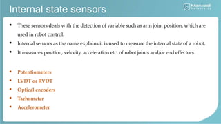
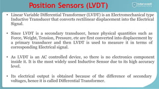
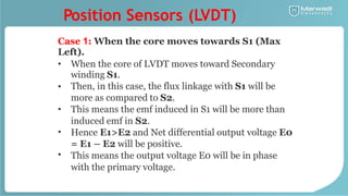
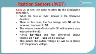
3. Common sensors used in robotics include position sensors, proximity sensors, range sensors, tactile sensors, and force sensors. Position sensors like LVDTs and RVDTs convert linear or angular displacement into electrical signals.