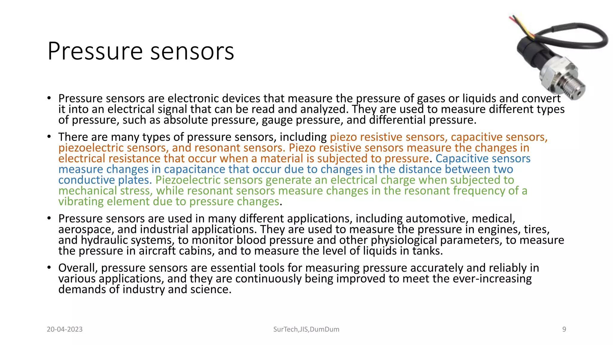
The document discusses different types of sensors, including displacement sensors like linear potentiometers and LVDTs, ultrasonic sensors, force sensors, temperature sensors, and pressure sensors. It provides details on how each sensor type works and describes common applications. The key points covered are the operating principles of common sensor technologies, their uses in fields like automation, medical, and manufacturing, and how sensors convert physical properties into electrical signals that can be measured.
This slide comprises a very rudimentary introduction of Industrial Instrumentation.
These slides may help students understand the aspects the Industrial Instrumentation.
This slide comprises a very rudimentary introduction of Industrial Instrumentation.
These slides may help students understand the aspects the Industrial Instrumentation.
It is often said that drawing is engineers’ language. Drawings are used to communicate and share information between different teams of engineers; the design engineer who conceptualises an equipment or system, the production engineer who plans the steps in manufacturing the required components and subsystems, the assembly engineer who puts the components together, the testing engineer who tests the complete system, the installation engineer who installs the system or equipment and the maintenance engineer who is responsible for its upkeep. To all these engineers with diverse backgrounds and expertise, a drawing should convey precise and identical information. This calls for standardised methodologies, conventions and approach in preparing drawings. This workshop will cover all these aspects with respect to engineering drawings in general and electrical drawings in particular. Various types of electrical drawings and their application, the steps in planning a drawing, selection of drawing size and scale, use of standardised symbols etc will be described in detail with commonly used examples from industry practice.
Computer Aided Drafting (CAD) has brought about a major change in the way drawings are prepared and has caused a phenomenal improvement in drawing office productivity. No organisation can afford to use the older manual methods of preparing drawings today. Apart from reuse and easy modification of existing drawings to create new ones, complete or partial automated drawing preparation has also become a possibility. The workshop discusses the advances made in this field and the links between drawings and manufacturing using 3D visualisation tools and Computer Aided Manufacturing (CAM) approach.
Use of CAD-CAM tools presents its own challenges in the way drawings are stored, shared between different groups of users and revised for reuse. The workshop also covers these aspects and takes a look at future possibilities in the way drawings will be used to disseminate information.
MORE INFORMATION - http://www.idc-online.com/content/electrical-drawings-and-schematics-25
The transducer whose resistance varies because of the environmental effects such type of transducer is known as the resistive transducer. The change in resistance is measured by the ac or dc measuring devices. The resistive transducer is used for measuring the physical quantities like temperature, displacement, vibration etc.
The measurement of the physical quantity is quite difficult. The resistive transducer converts the physical quantities into variable resistance which is easily measured by the meters. The process of variation in resistance is widely used in the industrial applications.
The resistive transducer can work both as the primary as well as the secondary transducer. The primary transducer changes the physical quantities into a mechanical signal, and secondary transducer directly transforms it into an electrical signal.
Working Principle of Resistive Transducer
The resistive transducer element works on the principle that the resistance of the element is directly proportional to the length of the conductor and inversely proportional to the area of the conductor. equation-1
Where R – resistance in ohms.
A – cross-section area of the conductor in meter square.
L – Length of the conductor in meter square.
ρ – the resistivity of the conductor in materials in ohm meter.
The resistive transducer is designed by considering the variation of the length, area and resistivity of the metal.
Applications of Resistive Transducer
The following are the applications of the resistive transducer.
Potentiometer – The translation and rotatory potentiometer are the examples of the resistive transducers. The resistance of their conductor varies with the variation in their lengths which is used for the measurement of displacement.
Strain gauges – The resistance of their semiconductor material changes when the strain occurs on it. This property of metals is used for the measurement of the pressure, force-displacement etc.
Resistance Thermometer – The resistance of the metals changes because of changes in temperature. This property of conductor is used for measuring the temperature.
Thermistor – It works on the principle that the temperature coefficient of the thermistor material varies with the temperature. The thermistor has the negative temperature coefficient. The Negative temperature coefficient means the temperature is inversely proportional to resistance.
Electrical Safety. Electrical hazards can cause burns, shocks and electrocution (death). Assume that all overhead wires are energized at lethal voltages. Never assume that a wire is safe to touch even if it is down or appears to be insulated.
An RTD (Resistance Temperature Detector) is a sensor whose resistance changes as its temperature changes. The resistance increases as the temperature of the sensor increases. The resistance vs temperature relationship is well known and is repeatable over time. An RTD is a passive device. It does not produce an output on its own. External electronic devices are used to measure the resistance of the sensor by passing a small electrical current through the sensor to generate a voltage. Typically 1 mA or less measuring current, 5 mA maximum without the risk of self-heating.
RTDs are built to several standardized curves and tolerances.
The most common standardized curve is the ‘DIN’ curve. The curve describes the resistance vs temperature characteristics of a Platinum, 100 ohm sensor, the standardized tolerances, and the measurable temperature range.
The DIN standard specifies a base resistance of 100 ohms at 0°C, and a temperature coefficient of .00385 Ohm/Ohm/°C. The nominal output of a DIN RTD sensor is shown below:
There are three standard tolerance classes for DIN RTDs. These tolerances are defined as follows:
DIN Class A: ±(0.15 + .002 |T|°C)
DIN Class B: ±(0.3 + .005 |T|°C)
DIN Class C: ±(1.2 + .005 |T|°C)
Sensors in Different Application Area Topics Covered: Occupancy and Motion Detectors; Position, Displacement, and Level; Velocity and Acceleration; Force, Strain, and Tactile Sensors; Pressure Sensors, Temperature Sensors
International Journal of Engineering Research and DevelopmentIJERD Editor
Electrical, Electronics and Computer Engineering,
Information Engineering and Technology,
Mechanical, Industrial and Manufacturing Engineering,
Automation and Mechatronics Engineering,
Material and Chemical Engineering,
Civil and Architecture Engineering,
Biotechnology and Bio Engineering,
Environmental Engineering,
Petroleum and Mining Engineering,
Marine and Agriculture engineering,
Aerospace Engineering.
Different transformations and reference
frame theory, modeling of induction machines, voltage fed inverter
control-v/f control, vector control, direct torque and flux
control(DTC).
PWM control of inverter,
selected harmonic elimination, space vector modulation, current
control of VSI, three level inverter, Different topologies, SVM for 3
level inverter, Diode rectifier with boost chopper, PWM converter as
line side rectifier, current fed inverters with self-commutated
devices. Control of CSI, H bridge as a 4-Q drive.
Online aptitude test management system project report.pdfKamal Acharya
The purpose of on-line aptitude test system is to take online test in an efficient manner and no time wasting for checking the paper. The main objective of on-line aptitude test system is to efficiently evaluate the candidate thoroughly through a fully automated system that not only saves lot of time but also gives fast results. For students they give papers according to their convenience and time and there is no need of using extra thing like paper, pen etc. This can be used in educational institutions as well as in corporate world. Can be used anywhere any time as it is a web based application (user Location doesn’t matter). No restriction that examiner has to be present when the candidate takes the test.
Every time when lecturers/professors need to conduct examinations they have to sit down think about the questions and then create a whole new set of questions for each and every exam. In some cases the professor may want to give an open book online exam that is the student can take the exam any time anywhere, but the student might have to answer the questions in a limited time period. The professor may want to change the sequence of questions for every student. The problem that a student has is whenever a date for the exam is declared the student has to take it and there is no way he can take it at some other time. This project will create an interface for the examiner to create and store questions in a repository. It will also create an interface for the student to take examinations at his convenience and the questions and/or exams may be timed. Thereby creating an application which can be used by examiners and examinee’s simultaneously.
Examination System is very useful for Teachers/Professors. As in the teaching profession, you are responsible for writing question papers. In the conventional method, you write the question paper on paper, keep question papers separate from answers and all this information you have to keep in a locker to avoid unauthorized access. Using the Examination System you can create a question paper and everything will be written to a single exam file in encrypted format. You can set the General and Administrator password to avoid unauthorized access to your question paper. Every time you start the examination, the program shuffles all the questions and selects them randomly from the database, which reduces the chances of memorizing the questions.
Water billing management system project report.pdfKamal Acharya
Our project entitled “Water Billing Management System” aims is to generate Water bill with all the charges and penalty. Manual system that is employed is extremely laborious and quite inadequate. It only makes the process more difficult and hard.
The aim of our project is to develop a system that is meant to partially computerize the work performed in the Water Board like generating monthly Water bill, record of consuming unit of water, store record of the customer and previous unpaid record.
We used HTML/PHP as front end and MYSQL as back end for developing our project. HTML is primarily a visual design environment. We can create a android application by designing the form and that make up the user interface. Adding android application code to the form and the objects such as buttons and text boxes on them and adding any required support code in additional modular.
MySQL is free open source database that facilitates the effective management of the databases by connecting them to the software. It is a stable ,reliable and the powerful solution with the advanced features and advantages which are as follows: Data Security.MySQL is free open source database that facilitates the effective management of the databases by connecting them to the software.
Literature Review Basics and Understanding Reference Management.pptxDr Ramhari Poudyal
Three-day training on academic research focuses on analytical tools at United Technical College, supported by the University Grant Commission, Nepal. 24-26 May 2024
A review on techniques and modelling methodologies used for checking electrom...nooriasukmaningtyas
The proper function of the integrated circuit (IC) in an inhibiting electromagnetic environment has always been a serious concern throughout the decades of revolution in the world of electronics, from disjunct devices to today’s integrated circuit technology, where billions of transistors are combined on a single chip. The automotive industry and smart vehicles in particular, are confronting design issues such as being prone to electromagnetic interference (EMI). Electronic control devices calculate incorrect outputs because of EMI and sensors give misleading values which can prove fatal in case of automotives. In this paper, the authors have non exhaustively tried to review research work concerned with the investigation of EMI in ICs and prediction of this EMI using various modelling methodologies and measurement setups.
Hierarchical Digital Twin of a Naval Power SystemKerry Sado
A hierarchical digital twin of a Naval DC power system has been developed and experimentally verified. Similar to other state-of-the-art digital twins, this technology creates a digital replica of the physical system executed in real-time or faster, which can modify hardware controls. However, its advantage stems from distributing computational efforts by utilizing a hierarchical structure composed of lower-level digital twin blocks and a higher-level system digital twin. Each digital twin block is associated with a physical subsystem of the hardware and communicates with a singular system digital twin, which creates a system-level response. By extracting information from each level of the hierarchy, power system controls of the hardware were reconfigured autonomously. This hierarchical digital twin development offers several advantages over other digital twins, particularly in the field of naval power systems. The hierarchical structure allows for greater computational efficiency and scalability while the ability to autonomously reconfigure hardware controls offers increased flexibility and responsiveness. The hierarchical decomposition and models utilized were well aligned with the physical twin, as indicated by the maximum deviations between the developed digital twin hierarchy and the hardware.
KuberTENes Birthday Bash Guadalajara - K8sGPT first impressionsVictor Morales
K8sGPT is a tool that analyzes and diagnoses Kubernetes clusters. This presentation was used to share the requirements and dependencies to deploy K8sGPT in a local environment.
2. DISPLACEMENT SESNOR
• Linear Potentiometer: A linear potentiometer is a type of
displacement sensor that measures linear movement. It consists of a
resistive element and a wiper that moves along the resistor as the
object being measured moves. As the wiper moves, it changes the
resistance, which is then measured to determine the displacement.
2
20-04-2023 SurTech,JIS,DumDum
3. DISPLACEMENT SESNOR
• LVDT (Linear Variable Differential Transformer):The LVDT is another
type of displacement sensor that measures linear movement. It
consists of a primary coil, two secondary coils, and a movable core. As
the object being measured moves, the core moves within the coils,
changing the inductance of the coils. This change in inductance is
then measured to determine the displacement.
3
20-04-2023 SurTech,JIS,DumDum
4. DISPLACEMENT SESNOR
• Capacitive Displacement Sensor: The capacitive displacement sensor
measures changes in capacitance to determine displacement. It
consists of two conductive plates separated by a dielectric material.
As the object being measured moves, it changes the distance
between the plates, which changes the capacitance. This change in
capacitance is then measured to determine the displacement.
4
20-04-2023 SurTech,JIS,DumDum
5. DISPLACEMENT SESNOR
• Eddy Current Displacement Sensor: The eddy current displacement
sensor uses electromagnetic induction to measure displacement. It
consists of a coil and a conductive target. As the target moves, it
induces eddy currents in the target, which then create a magnetic
field that is sensed by the coil. This change in magnetic field is then
measured to determine the displacement.
5
20-04-2023 SurTech,JIS,DumDum
6. Ultrasonic sensors
• Ultrasonic sensors are electronic devices that use sound waves to detect the
presence, distance, and other properties of objects. They work by emitting high-
frequency sound waves that bounce off nearby objects and return to the sensor.
By measuring the time it takes for the sound waves to travel to and from the
object, the sensor can determine the distance to the object.
• Ultrasonic sensors are commonly used in automation and robotics applications,
such as object detection, distance measurement, and position sensing. They can
also be used in medical equipment, automotive applications, and home security
systems.
• Ultrasonic sensors have some advantages over other types of sensors, such as
infrared or optical sensors. They can detect objects regardless of color or texture,
and they are less affected by ambient light. However, they may have difficulty
detecting objects with irregular shapes or surfaces, and their accuracy may be
affected by environmental factors such as temperature and humidity.
6
20-04-2023 SurTech,JIS,DumDum
7. Force Sensors
• Force sensors are electronic devices that measure the force applied to them. They convert the
physical force into an electrical signal that can be measured and analyzed. Force sensors can be
used to measure a wide range of forces, from small forces in the milli newton range to large
forces in the kilo newton range.
• There are different types of force sensors, including strain gauge sensors, piezoelectric sensors,
capacitive sensors, and magnetic sensors. Strain gauge sensors are the most common type of
force sensor and work by measuring the strain or deformation of a material under stress.
Piezoelectric sensors generate an electrical charge when they are subjected to mechanical stress,
while capacitive sensors measure changes in capacitance due to the applied force. Magnetic
sensors measure the changes in magnetic fields that are produced by the applied force.
• Force sensors have a wide range of applications in various fields, such as manufacturing, robotics,
medical equipment, and aerospace. They can be used to measure forces in machines, to monitor
the performance of engines, to measure the force exerted by a human hand or foot, and to
measure the forces involved in material testing.
• Overall, force sensors are essential tools for measuring forces accurately and reliably in various
applications, and they are continuously being improved to meet the ever-increasing demands of
industry and science.
7
20-04-2023 SurTech,JIS,DumDum
8. Temperature sensors
• Temperature sensors are electronic devices that measure temperature and convert it into an electrical signal that can be read and
analyzed. There are many types of temperature sensors, each with its own set of advantages and limitations.
• One of the most common types of temperature sensors is the thermocouple, which works by measuring the voltage generated
when two different metals are joined together and subjected to a temperature gradient. Another common type of temperature
sensor is the resistance temperature detector (RTD), which measures changes in electrical resistance in response to temperature
changes. Thermistors are another type of temperature sensor that work by measuring changes in electrical resistance in response
to temperature changes, but they have a different resistance-temperature characteristic compared to RTDs.
• In addition to these types of sensors, there are also infrared temperature sensors that work by measuring the amount of infrared
radiation emitted by an object, which can be used to determine its temperature without making physical contact. These sensors
are commonly used in industrial applications, where they can measure the temperature of objects that are too hot to touch or too
far away to reach.
• Temperature sensors have a wide range of applications in many fields, including manufacturing, automotive, aerospace, medical
equipment, and environmental monitoring. They are used to monitor and control temperature in various processes, to ensure
product quality, and to protect equipment from damage due to overheating.
• Overall, temperature sensors are essential tools for measuring temperature accurately and reliably in various applications, and
they play an important role in ensuring the safety, efficiency, and quality of many processes and products.
8
20-04-2023 SurTech,JIS,DumDum
9. Pressure sensors
• Pressure sensors are electronic devices that measure the pressure of gases or liquids and convert
it into an electrical signal that can be read and analyzed. They are used to measure different types
of pressure, such as absolute pressure, gauge pressure, and differential pressure.
• There are many types of pressure sensors, including piezo resistive sensors, capacitive sensors,
piezoelectric sensors, and resonant sensors. Piezo resistive sensors measure the changes in
electrical resistance that occur when a material is subjected to pressure. Capacitive sensors
measure changes in capacitance that occur due to changes in the distance between two
conductive plates. Piezoelectric sensors generate an electrical charge when subjected to
mechanical stress, while resonant sensors measure changes in the resonant frequency of a
vibrating element due to pressure changes.
• Pressure sensors are used in many different applications, including automotive, medical,
aerospace, and industrial applications. They are used to measure the pressure in engines, tires,
and hydraulic systems, to monitor blood pressure and other physiological parameters, to measure
the pressure in aircraft cabins, and to measure the level of liquids in tanks.
• Overall, pressure sensors are essential tools for measuring pressure accurately and reliably in
various applications, and they are continuously being improved to meet the ever-increasing
demands of industry and science.
9
20-04-2023 SurTech,JIS,DumDum