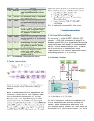
This document discusses the hardware implementation of a wireless backscatter communication protocol for brain-controlled spinal interfaces (BCSIs), designed to aid rehabilitation for patients with spinal cord injuries by allowing direct neural signal decoding and spinal cord stimulation. The focus is on the implant-side implementation using low-power FPGA, the clinical significance of BCSIs, as well as detailing the communication protocol requirements between the external reader and implanted neural sensors. The research aims to enhance portability and efficiency in decoding neural signals while fostering neuroplasticity to restore movement capabilities in patients.
![ending up with the power in the desired frequency band over
time. The core part of our decoder is a canonical correlation
analysis (CCA) filter, which we train with the data. This filter
results in a set of coefficients, one for each channel. We can
then linearly combine (multiply and add) the weighted band
power from each channel to result in a signal which finally
predicts lever movement, as seen in Figure 7.
Fig. 7. Real level movement (blue) and roughly decoded lever
movement (red). Adapted from code by Nicholas Tolley.
After placing a threshold on predicted movement, we can
stimulate the spinal cord whenever that threshold is crossed,
i.e. when the prediction is strong enough, resulting in
activity-dependent stimulation.
Ultimately, we can consider the BCSI as artificial neurons
which promotes a new neural pathway around an injury in the
cervical spinal cord which severed a previous neural pathway:
decoding one’s intention to move, then encoding that intention
as stimulation to promote muscle movement.
III. Implementing BCSIs
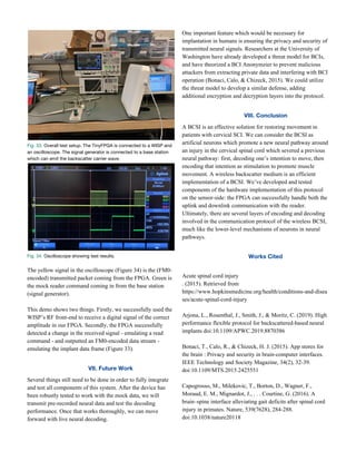
Through developing the BCSI, the primary way of performing
the decoding has been via the TDT (Tucker-Davis
Technologies) system - a large, rack-mounted lab computer -
as pictured in Figure 8.
Fig. 8. Soshi Samejima using the TDT (photo taken by Nicholas
Tolley).
The development of this device will have to go beyond this
medium in order to be mobile. The electrodes used to record
the LFPs and the electrodes used to stimulate the spinal cord
are already small and relatively power-efficient, i.e. already
suitable for mobile use. However, this large computer
in-between which takes care of the computationally-intensive
(and thus power-hungry) decoding is not suitable for portable
use.
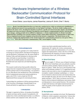
One method of implementing the BCSI decoding is via a
completely implanted application-specific integrated circuit
(ASIC) derived from an FPGA (field-programmable gate
array) which can perform the decoding. Such a device has
been developed by Ranganathan et al., called the Neural
Closed-Loop Implantable Platform (NeuralCLIP) shown in
Figure 9. Power supply is already a concern with
medically-implantable devices; the main downside of the
NeuralCLIP is that it must be carefully and specifically
designed to handle the computational load efficiently.
An alternative implementation which circumvents this issue is
a wireless one: an external reader utilizing backscatter
communication to transfer the data from the implanted
electrodes to a computer which can do the intensive decoding.
The hardware for such a device has been developed by
Rosenthal et al., called NeuroDisc. The tradeoffs between the
different implementation approaches are summarized in Table
10.
Fig. 9. [Left] NeuralCLIP and [Right] NeuroDisc (Ranganathan et al.,
2019; Rosenthal, Kampianakis, Sharma, & Reynolds, 2018).
TDT Implanted Wireless
Computational Resources High Low High
Mobility / Duration Very Low High/ Med High
Battery-dependency High High Low
Communication Latency Very Low Low High
Tab. 10. Comparing different implementations of decoding in BCSI.
IV. The Wireless Protocol
A. Overview
In order to communicate the implanted system with the
external reader, a protocol is necessary to specify in what
forms information will be exchanged. On a high-level, the
protocol involves communication between only two
components: the (external) reader, and the (internal) sensor
implant. For consistency, we will refer to the following terms](https://image.slidesharecdn.com/anandsekarseniorthesis-200620054806/85/Senior-Thesis-4-320.jpg)
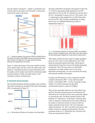
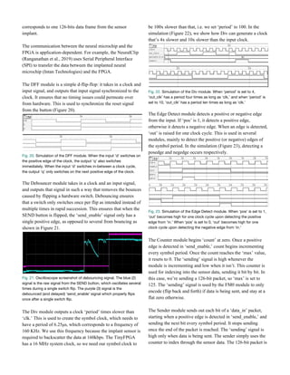
![Command Structure
Start [2b: 00 | 12b: device ID]
Read [2b: 01 | 16b: active channels | 8b: frame count]
Cont [2b: 10]
End [2b: 11 | 12b: device ID]
Tab. 14. Reader commands
Each command begins with a frame-synchronization
(frame-sync) pulse which is a 12.5μs delimiter followed by a
PIE-encoded 0 and calibration pulse, as shown in Figure 15.
Fig. 15. Frame-sync. PW refers to the duration of the Pulse Width.
C. Uplink Communication
The protocol supports up to 16 neural channels, with 16 bits
per channel. After recording the data with the electrodes, the
implant encodes the data using Hamming encoding, which is a
linear error-correcting code that can detect two-bit errors and
correct one-bit errors. The goal of error-correcting codes, like
Hamming, is to send redundant information in different ways,
such that the data is robust in a noisy environment. Here, we
specifically use H(11, 15) which transmits 15 total bits for
every 11 data bits.
Next, the reader applies an interleaving algorithm to the frame.
The goal of the interleaving process is to increase the
likelihood of correction/ detection of burst errors (which
become spread). In particular, we use a pattern interleaving
algorithm that requires a permutation vector with the same
length in bits as the frame. This vector will be predetermined
by the reader and implant, so that an adversary would not be
able to interpret the intercepted data.
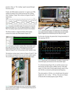
After the hamming and interleaving blocks, the resulting
frame bits are encoded via FM0. FM0, also known as
differential manchester encoding, is a line encoding scheme
which involves a switch on every symbol period. If the bit is
0, it switches again halfway through the period, otherwise if
the bit is 1, it stays constant during the period.
Fig. 16. FM0 encoding (shown by the yellow signal).
As seen in Figure 16, the transitions of the digital signal
indicate a logical value (1/ 0), not the value of the digital
signal itself (high/ low). One reason to use FM0 modulation to
wirelessly transmit the data from the implant is that a
transition is guaranteed at every bit boundary, making the
synchronization between the implant and the reader easier to
achieve. FM0 is also less error-prone in noisy environments
than simply comparing the signal levels against a threshold.
Moreover, it achieves Zero DC bias, i.e. if the high/ low
analog signals are the same magnitude/ opposite polarity, the
average voltage is zero, resulting in lower transmitting power
necessary and minimal noise (Schouhamer Immink &
Pátrovics, 1997).
Finally, the FM0-encoded frame is transmitted using ASK or
Phase-Shift Keying (PSK) as Binary-PSK (BPSK) or
Differential Quadrature PSK (DQPSK). Quadrature amplitude
modulation utilizes complex values to send two orthogonal
carrier waves, such that two bits can be sent per symbol,
yielding a higher data rate. DQPSK is the method used for
backscatter modulation in the NeuroDisc, but our current
implementation only uses ASK.
D. Backscatter Communication
One approach for the implant to send data to the reader would
be to actively generate and amplify its own carrier frequency.
However, this consumes a significant amount of power.
Another way for the implant to send data to the reader is for
the reader to broadcast a carrier wave, which the implant can
passively encode data on by switching the impedance on its
antennae, reflecting the carrier wave according to the data.
This approach was preferred and used for our system since it
consumes significantly less power (Rosenthal, Kampianakis,
Sharma, & Reynolds, 2018). The downside is that this results
in more path attenuation, i.e. power loss as a wave propagates
more distance, which could result in less reliable
communication in more noisy environments. To minimize the
impact of these possible errors, we used the hamming and
interleaving blocks.
E. OSI Model
The Open Systems Interconnection (OSI) model is a
hierarchical structure composed of layers which represents
how most modern communication infrastructures, such as the
Internet, work. This involves several layers of encapsulation -
from physical to application - to ensure robust (error-free)
communication. The OSI model applied to this protocol is
shown in Table 17.](https://image.slidesharecdn.com/anandsekarseniorthesis-200620054806/85/Senior-Thesis-6-320.jpg)