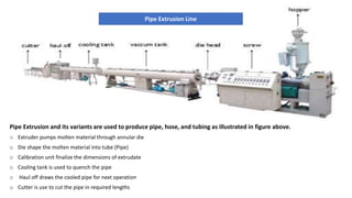
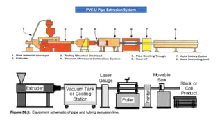
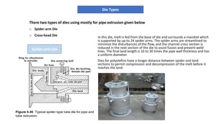
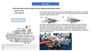
Pipe Extrusion Line
TALLINN UNIVERSITY OF TECHNOLOGY
PRESENTATION
POLYMER TECHNOLOGY-1
BY: WALI KHAN
Pipe Extrusion and its variants are used to produce pipe, hose, and tubing as illustrated in figure above.
o Extruder pumps molten material through annular die
o Die shape the molten material into tube (Pipe)
o Calibration unit finalize the dimensions of extrudate
o Cooling tank is used to quench the pipe
o Haul off draws the cooled pipe for next operation
o Cutter is use to cut the pipe in required lengths
Pipe Extrusion Line
PVC-U Pipe Extrusion System
o Extruder screw transport materials from hopper to metering zone
o Barrel heaters and friction inside barrel produces heat to melt materials
o Mix additives with primary material in molten state
o Produce homogeneous mixing
o Pump molten material though die
Extrusion Section
There two types of dies using mostly for pipe extrusion given below
o Spider-arm Die
o Cross-head Die
Die Types
Spider-arm Die
In this die, melt is fed from the base of die and surrounds a mandrel which
is supported by up-to 24 spider arms. The spider arms are streamlined to
minimize the disturbances of the flow, and the channel cross section is
reduced in the next section of the die to assist fusion and prevent weld
lines. The final land length is 10 to 30 times the pipe wall thickness and has
a uniform diameter.
Dies for polyolefins have a longer distance between spider and land
sections to permit compression and decompression of the melt before it
reaches the land.
There two types of dies using mostly for pipe extrusion given below
o Spider-arm Die
o Cross-head Die
Die Types
Cross-head Die
A cross-head die is transition piece that usually alters the direction of melt flow
in by 90° to coat the wire. Design of the cross-head should be streamlined with
minimum melt residence time.
The most common type of die for thermoplastic extrusion is tube die (A) that
extrudes thin wall tube around wire. The tube is drawn by vacuum onto the
wire after it leave the die. The vacuum is pulled the clearance between the
conductor and its passageway through cross-head. Type (B) is pressure die in
which the melt comes in contact with the wire prior to leaving the die while the
melt is under pressure.
1
5
67
11
10
4
9 8
12 13
2
3
o Screen pack or breaker plate die:
In this type of die, the mandrel is supported by a metal
screen containing 1-mm diameter holes that fits onto the
back of the mandrel. This design does not require a
compression zone due to the lack of spider arms and used
mainly for large-diameter polyolefin pipe.
o Spiral mandrel die:
A better solution, particularly for larger pipe die to avoid
weld lines is spiral mandrel die. Here the mandrel is rigidly
supported, and the melt flow is directed around it in an
initially helical pattern, which is converted to axial flow by
the geometry of the flow channels and lands. Weld lines are
eliminated but difficulty is to ensure an even flow rate at all
points of the die outlet.
As melt exits die, it swells slightly. Therefore, it requires size
adjustment, namely calibration.
Die Types
For the extrusion of pipes, profiles, and similar semi-finished products, the calibration and cooling sections are
connected to the die that has shaped the melt. The goal is to solidify the melt by contact with calibration (Sizing)
die in the calibration section to a thickness sufficient for transferring the take-off forces and still maintaining the
desired dimensions.
The calibration practically always means that the extrudate is pulled through one or more so-called calibrators,
made predominantly from metal (brass, steel, aluminum).
Pipe Calibration Systems
There are many kinds of advance calibration systems available now a days but here, only three will be discussed in detail
o Extended water-cooled mandrels
o Vacuum calibration
o Pressure calibration
o Friction calibration
o Internal calibration
o Precision extrusion pull forming
o Moveable calibrators
When extrudate is drawn along an extended water-cooled
mandrel, the diameter of the mandrel fixes the internal
diameter of the pipe or tubing. This mandrel is tapered to
compensate for shrinkage of the plastic and the pipe
thickness is controlled by the die gap and pull-off rate.
Although this system is difficult to control, it is used in
products where internal diameter is critical.
Pipe Calibration Systems
Water-cooledmandrel
In calibration with vacuum, the contact between the
calibrator system and the extruded profile necessary for
its cooling and sizing is achieved by applying vacuum to
the calibration equipment. In this process, the
equipment can surround the profile completely (closed
external sizing), the vacuum being applied through fine
boreholes or slits in the surrounding wall as shown in
figure. The profile is pulled through plates, between
which vacuum is applied
The main advantage of this process is that there is no
floating plug in the interior of the profile. It is only
necessary to maintain atmospheric pressure inside the
profile. For this purpose, boreholes for equalizing the air
pressure are arranged in the mandrel or cores of the
profile die.
Pipe Calibration Systems
VacuumCalibration
In contrast to vacuum, during pressure forming or
calibration through pressure, the air inside the
pipe is pressurized while the air out-side is the
pipe is at atmospheric pressure. The change in
pressure still forces the exterior of the pipe against
calibration rings, but a plug at the end of the pipe
prevents the air from escaping. Puller speed and
die gap again control the wall thickness. Pipes and
tubes are usually cooled in a water bath that is
part of the calibration unit and many lines require
a second water bath for high throughputs or for
profiling of the bath temperature.
Large diameter pipes dimensions are controlled by
pressure or vacuum calibration, and water is spray
system cools the pipe.
Pipe Calibration Systems
PressureCalibration
Haul-off units are part of pipe extrusion line, their main purpose is to pull
pipe through calibration unit, cooling tanks. The wall thickness is
determined by haul-off unit too.
Haul-off Systems
There are many kinds of plastic pipe cutters like conventional ones but plasma ray cutter and laser cutter
using as a advance technology in pipe cutting techniques.
Pipe Cutters
1. Handbook of thermoplastic elastomers (Second Edition) by Drobny, Jiri
2. Extrusion – The definitive processing guide and handbook by Giles, Harold
3. Extrusion Dies for Plastics and Rubber - Design and Engineering Computations (3rd Edition) by Michaeli, Walter
4. Modern Plastics Handbook by Charles A. Harper
References

Pipe Extrusion Line

  • 1.
    Pipe Extrusion Line TALLINNUNIVERSITY OF TECHNOLOGY PRESENTATION POLYMER TECHNOLOGY-1 BY: WALI KHAN
  • 2.
    Pipe Extrusion andits variants are used to produce pipe, hose, and tubing as illustrated in figure above. o Extruder pumps molten material through annular die o Die shape the molten material into tube (Pipe) o Calibration unit finalize the dimensions of extrudate o Cooling tank is used to quench the pipe o Haul off draws the cooled pipe for next operation o Cutter is use to cut the pipe in required lengths Pipe Extrusion Line
  • 3.
  • 4.
    o Extruder screwtransport materials from hopper to metering zone o Barrel heaters and friction inside barrel produces heat to melt materials o Mix additives with primary material in molten state o Produce homogeneous mixing o Pump molten material though die Extrusion Section
  • 5.
    There two typesof dies using mostly for pipe extrusion given below o Spider-arm Die o Cross-head Die Die Types Spider-arm Die In this die, melt is fed from the base of die and surrounds a mandrel which is supported by up-to 24 spider arms. The spider arms are streamlined to minimize the disturbances of the flow, and the channel cross section is reduced in the next section of the die to assist fusion and prevent weld lines. The final land length is 10 to 30 times the pipe wall thickness and has a uniform diameter. Dies for polyolefins have a longer distance between spider and land sections to permit compression and decompression of the melt before it reaches the land.
  • 6.
    There two typesof dies using mostly for pipe extrusion given below o Spider-arm Die o Cross-head Die Die Types Cross-head Die A cross-head die is transition piece that usually alters the direction of melt flow in by 90° to coat the wire. Design of the cross-head should be streamlined with minimum melt residence time. The most common type of die for thermoplastic extrusion is tube die (A) that extrudes thin wall tube around wire. The tube is drawn by vacuum onto the wire after it leave the die. The vacuum is pulled the clearance between the conductor and its passageway through cross-head. Type (B) is pressure die in which the melt comes in contact with the wire prior to leaving the die while the melt is under pressure. 1 5 67 11 10 4 9 8 12 13 2 3
  • 7.
    o Screen packor breaker plate die: In this type of die, the mandrel is supported by a metal screen containing 1-mm diameter holes that fits onto the back of the mandrel. This design does not require a compression zone due to the lack of spider arms and used mainly for large-diameter polyolefin pipe. o Spiral mandrel die: A better solution, particularly for larger pipe die to avoid weld lines is spiral mandrel die. Here the mandrel is rigidly supported, and the melt flow is directed around it in an initially helical pattern, which is converted to axial flow by the geometry of the flow channels and lands. Weld lines are eliminated but difficulty is to ensure an even flow rate at all points of the die outlet. As melt exits die, it swells slightly. Therefore, it requires size adjustment, namely calibration. Die Types
  • 8.
    For the extrusionof pipes, profiles, and similar semi-finished products, the calibration and cooling sections are connected to the die that has shaped the melt. The goal is to solidify the melt by contact with calibration (Sizing) die in the calibration section to a thickness sufficient for transferring the take-off forces and still maintaining the desired dimensions. The calibration practically always means that the extrudate is pulled through one or more so-called calibrators, made predominantly from metal (brass, steel, aluminum). Pipe Calibration Systems There are many kinds of advance calibration systems available now a days but here, only three will be discussed in detail o Extended water-cooled mandrels o Vacuum calibration o Pressure calibration o Friction calibration o Internal calibration o Precision extrusion pull forming o Moveable calibrators
  • 9.
    When extrudate isdrawn along an extended water-cooled mandrel, the diameter of the mandrel fixes the internal diameter of the pipe or tubing. This mandrel is tapered to compensate for shrinkage of the plastic and the pipe thickness is controlled by the die gap and pull-off rate. Although this system is difficult to control, it is used in products where internal diameter is critical. Pipe Calibration Systems Water-cooledmandrel
  • 10.
    In calibration withvacuum, the contact between the calibrator system and the extruded profile necessary for its cooling and sizing is achieved by applying vacuum to the calibration equipment. In this process, the equipment can surround the profile completely (closed external sizing), the vacuum being applied through fine boreholes or slits in the surrounding wall as shown in figure. The profile is pulled through plates, between which vacuum is applied The main advantage of this process is that there is no floating plug in the interior of the profile. It is only necessary to maintain atmospheric pressure inside the profile. For this purpose, boreholes for equalizing the air pressure are arranged in the mandrel or cores of the profile die. Pipe Calibration Systems VacuumCalibration
  • 11.
    In contrast tovacuum, during pressure forming or calibration through pressure, the air inside the pipe is pressurized while the air out-side is the pipe is at atmospheric pressure. The change in pressure still forces the exterior of the pipe against calibration rings, but a plug at the end of the pipe prevents the air from escaping. Puller speed and die gap again control the wall thickness. Pipes and tubes are usually cooled in a water bath that is part of the calibration unit and many lines require a second water bath for high throughputs or for profiling of the bath temperature. Large diameter pipes dimensions are controlled by pressure or vacuum calibration, and water is spray system cools the pipe. Pipe Calibration Systems PressureCalibration
  • 12.
    Haul-off units arepart of pipe extrusion line, their main purpose is to pull pipe through calibration unit, cooling tanks. The wall thickness is determined by haul-off unit too. Haul-off Systems
  • 13.
    There are manykinds of plastic pipe cutters like conventional ones but plasma ray cutter and laser cutter using as a advance technology in pipe cutting techniques. Pipe Cutters
  • 14.
    1. Handbook ofthermoplastic elastomers (Second Edition) by Drobny, Jiri 2. Extrusion – The definitive processing guide and handbook by Giles, Harold 3. Extrusion Dies for Plastics and Rubber - Design and Engineering Computations (3rd Edition) by Michaeli, Walter 4. Modern Plastics Handbook by Charles A. Harper References