Downloaded 186 times
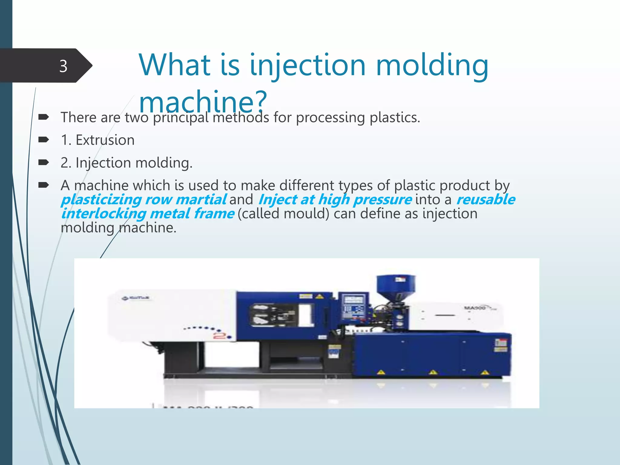
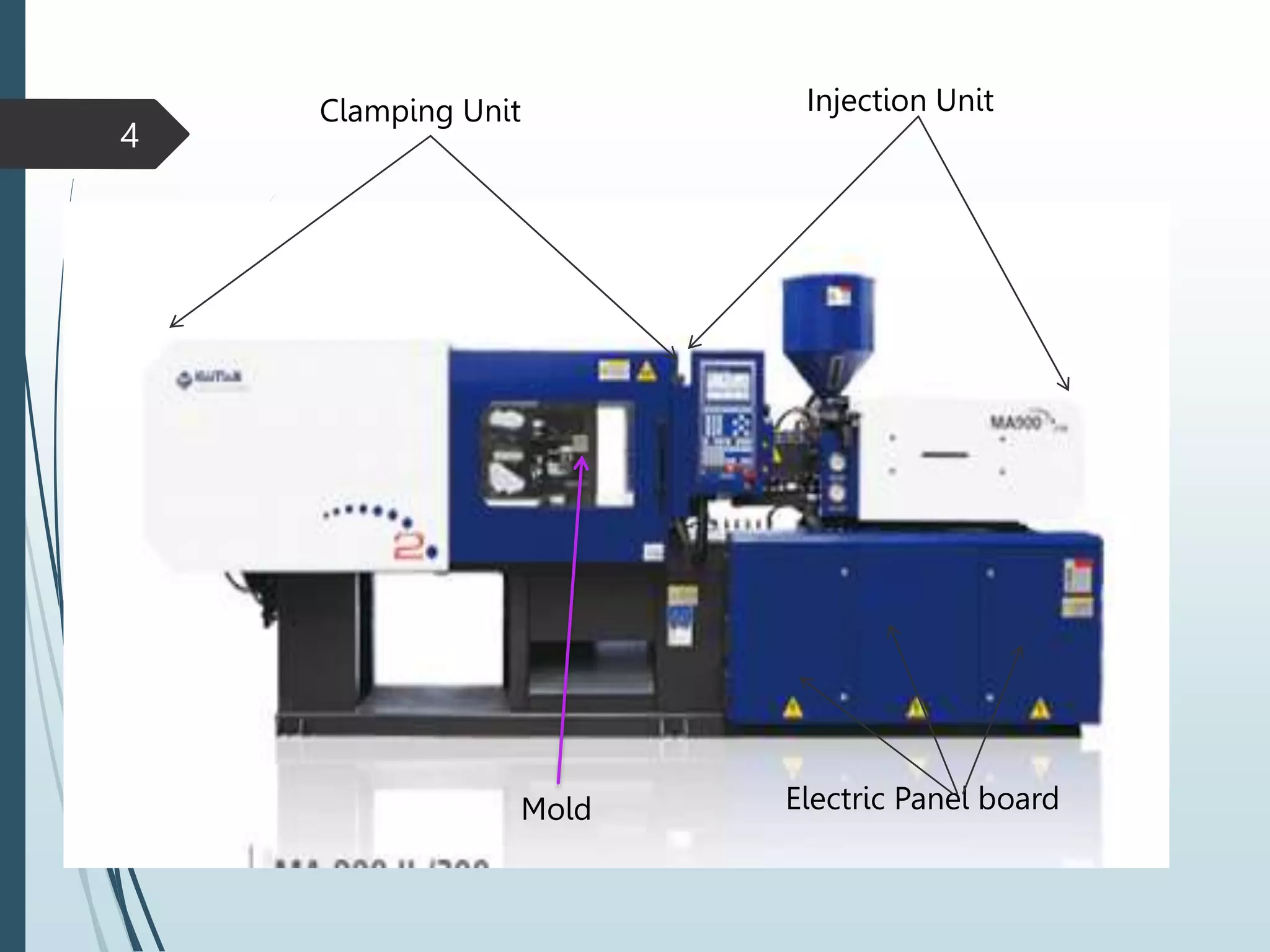


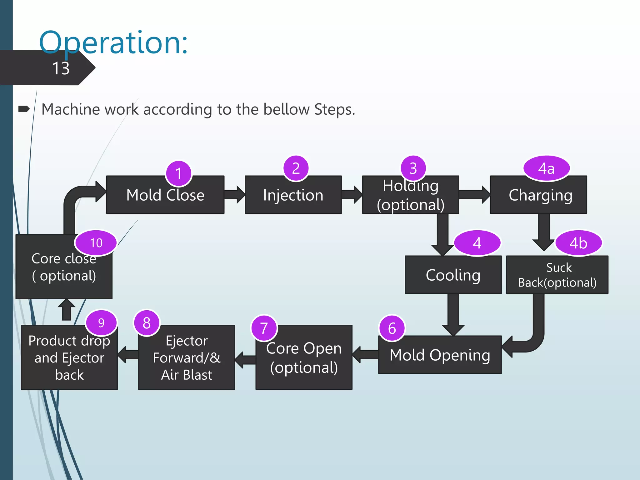

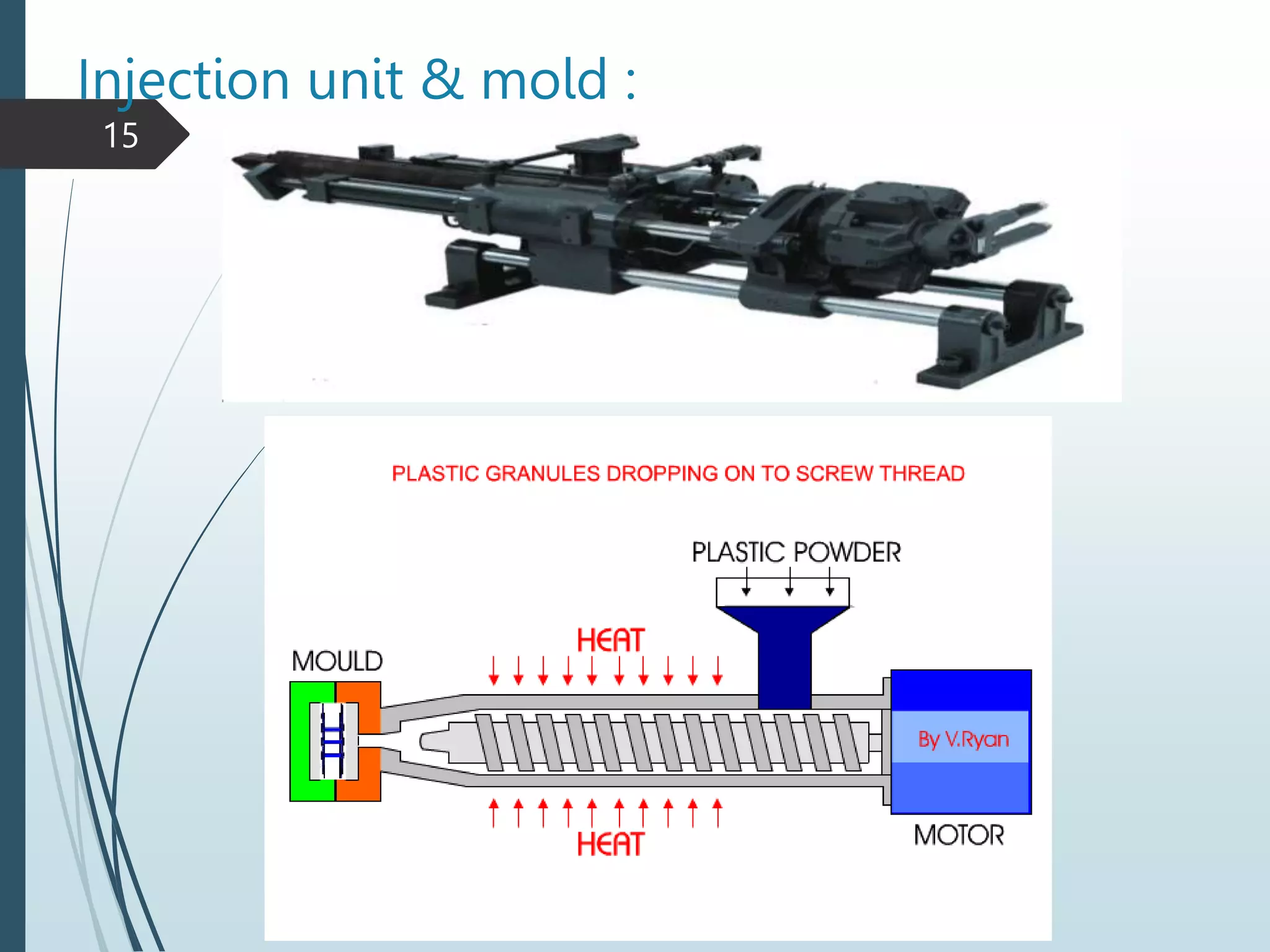


This document provides an overview of injection molding machines and their components and operation. It begins with defining injection molding as a process that uses heat and pressure to mold raw plastic materials into products within a reusable metal mold. It then describes the main parts of the machine including the clamping unit, injection unit, mold, and electric panel board. The document provides details on the injection and clamping processes, parameter settings, common product defects, and safety procedures. It also includes a section for maintenance technicians that covers the machine's energy flow, control system, key equipment, and safety checks.


