Download to read offline
![International Research Journal of Engineering and Technology (IRJET) e-ISSN: 2395-0056
Volume: 06 Issue: 03 | Mar 2019 www.irjet.net p-ISSN: 2395-0072
© 2019, IRJET | Impact Factor value: 7.211 | ISO 9001:2008 Certified Journal | Page 8220
PLASTIC INJECTION MOULDING MACHINE
Gaikwad Mahesh Digamber1, Sharif Mohiuddin Akbar2, Dhomase Datta Govind3, Ravale
Shivshankar Ashokrao4 ,Mr Bidve Mangesh Angadrao5,Mr Devshette Ashish Rajkumar6
1,2,3,4 Students, Diploma in Mechanical Engineering, Vishweshwarayya Abhiyantriki Padvika Mahavidyalay,
Almala, Maharashtra, India.
5HOD, Department Of Mechanical Engineering, Vishweshwarayya Abhiyantriki Padvika Mahavidyalay, Almala,
Maharashtra, India.
6Project Guide, Lecturer, Department Of Mechanical Engineering, Vishweshwarayya Abhiyantriki Padvika
Mahavidyalay, Almala, Maharashtra, India.
--------------------------------------------------------------------***---------------------------------------------------------------------
Abstract - Due to environment of competition, industries
are into heavy pressure to produce products at a rapid rate.
This led to evolve new technologies and production processes.
Plastic injection moulding process is one of the production
technique used to produce plastic products at a rapid rate
with minimum defects, but it is a complex process in terms of
product, process parameters, and production set-up. Injection
moulding has been a challenging process for many
manufacturers and researchers to produce products meeting
requirements at the lowestcost. Facedwithglobalcompetition
in injection moulding industry, using the trial and error
approach to determine the process parameters for injection
moulding is no longer good enough. Factors that affect the
quality of a moulded part can be classified into four
categories: part design, mould design, machine performance
and processing conditions. The part and mould design are
assumed as established and fixed. During production, quality
characteristics may deviate due to drifting or shifting of
processing conditions caused bymachine wear, environmental
change or operator fatigue.
Development of small injection moulding machinefor forming
small plastic articles in small-scaleindustries wasstudied. This
work which entailed design, construction and test small
injection moulding machine thatwascapableofformingsmall
plastic articles by injecting molten resins into a closed, cooled
mould, where it solidifies to give the desired products was
developed. The machine wasdesignedandconstructedto work
as a prototype for producing very small plastic components.
Design concept, operation, and assembly of components parts
were made.
Key Words: Development, Injection, Moulding,
Machine, Plastics, Industries, Quality,
1. INTRODUCTION
Plastic waste is one of the greatest sources of waste which
has been increasing since the plastic was first used as a daily
need product. But, most danger property of plastic is that is
does not degrade with time which makes it difficult to
dispose. Plastic are said to remain in the environment for
billions of years. Good quality of plastic is that it can be
Recycled or Reused. So, there is only one way to make is less
dangerous by using the good quality, and that isbyreusingit
or recycling it. We can reuse some of the products, like
plastic bottles, but there are so many products that cannot
be reused. So, plastic recycling is the process through which
we can use these plastic to create new products. So, we
decided to make a plastic recycling machine that can reuse
shredded plastic to make useful product and at a cheaper
cost. The most common methods of processing plastics to
manufacture plastic parts include Extrusion, Injection
molding, plastic injection moulding process,Blowmoulding,
Casting, etc. Among these, perhaps injection moulding is the
most significant for local industry – almostall manufacturing
companies use parts that are injection moulded, whether
they make toys, home-appliances, electronics or electrical
parts, watches, computers. In Plastic Injection moulding
process, plastic products are produced by forcing the resins
made of plastic materials byapplicationofhighpressureinto
a mould where it is cooled, allowed to solidify and after that
taken out from the mould by opening cop and drag part of
the mould. Articles having complicated shapes and
geometries with great dimensional accuracy can be easily
produced by the plastic injection moulding process [3].
Plastic injection moulding machine consist of three units
namely Clamping Unit, the Injection Unit, and the DriveUnit.
The functions of the clamping unit are to hold the mould,
close and open during the operation. The fixed and moving
plates, the tie bars and the mechanism for opening, closing
and clamping are the parts of the clamping unit. The
injection unit or plasticizing unit melts the polymer resins
and injects it into the mould. The drive unit provides power
to the plasticizing unit and clamping unit. The Basic
requirement to produce article by plasticinjection moulding
process is the preparation of mould, runner system, gate
location and sprue designandselectioncoolingchannelsand
location of the cooling channels [4].](https://image.slidesharecdn.com/irjet-v6i31027-190926092244/85/IRJET-Plastic-Injection-Moulding-Machine-1-320.jpg)
![International Research Journal of Engineering and Technology (IRJET) e-ISSN: 2395-0056
Volume: 06 Issue: 03 | Mar 2019 www.irjet.net p-ISSN: 2395-0072
© 2019, IRJET | Impact Factor value: 7.211 | ISO 9001:2008 Certified Journal | Page 8220
PLASTIC INJECTION MOULDING MACHINE
Gaikwad Mahesh Digamber1, Sharif Mohiuddin Akbar2, Dhomase Datta Govind3, Ravale
Shivshankar Ashokrao4 ,Mr Bidve Mangesh Angadrao5,Mr Devshette Ashish Rajkumar6
1,2,3,4 Students, Diploma in Mechanical Engineering, Vishweshwarayya Abhiyantriki Padvika Mahavidyalay,
Almala, Maharashtra, India.
5HOD, Department Of Mechanical Engineering, Vishweshwarayya Abhiyantriki Padvika Mahavidyalay, Almala,
Maharashtra, India.
6Project Guide, Lecturer, Department Of Mechanical Engineering, Vishweshwarayya Abhiyantriki Padvika
Mahavidyalay, Almala, Maharashtra, India.
--------------------------------------------------------------------***---------------------------------------------------------------------
Abstract - Due to environment of competition, industries
are into heavy pressure to produce products at a rapid rate.
This led to evolve new technologies and production processes.
Plastic injection moulding process is one of the production
technique used to produce plastic products at a rapid rate
with minimum defects, but it is a complex process in terms of
product, process parameters, and production set-up. Injection
moulding has been a challenging process for many
manufacturers and researchers to produce products meeting
requirements at the lowestcost. Facedwithglobalcompetition
in injection moulding industry, using the trial and error
approach to determine the process parameters for injection
moulding is no longer good enough. Factors that affect the
quality of a moulded part can be classified into four
categories: part design, mould design, machine performance
and processing conditions. The part and mould design are
assumed as established and fixed. During production, quality
characteristics may deviate due to drifting or shifting of
processing conditions caused bymachine wear, environmental
change or operator fatigue.
Development of small injection moulding machinefor forming
small plastic articles in small-scaleindustries wasstudied. This
work which entailed design, construction and test small
injection moulding machine thatwascapableofformingsmall
plastic articles by injecting molten resins into a closed, cooled
mould, where it solidifies to give the desired products was
developed. The machine wasdesignedandconstructedto work
as a prototype for producing very small plastic components.
Design concept, operation, and assembly of components parts
were made.
Key Words: Development, Injection, Moulding,
Machine, Plastics, Industries, Quality,
1. INTRODUCTION
Plastic waste is one of the greatest sources of waste which
has been increasing since the plastic was first used as a daily
need product. But, most danger property of plastic is that is
does not degrade with time which makes it difficult to
dispose. Plastic are said to remain in the environment for
billions of years. Good quality of plastic is that it can be
Recycled or Reused. So, there is only one way to make is less
dangerous by using the good quality, and that isbyreusingit
or recycling it. We can reuse some of the products, like
plastic bottles, but there are so many products that cannot
be reused. So, plastic recycling is the process through which
we can use these plastic to create new products. So, we
decided to make a plastic recycling machine that can reuse
shredded plastic to make useful product and at a cheaper
cost. The most common methods of processing plastics to
manufacture plastic parts include Extrusion, Injection
molding, plastic injection moulding process,Blowmoulding,
Casting, etc. Among these, perhaps injection moulding is the
most significant for local industry – almostall manufacturing
companies use parts that are injection moulded, whether
they make toys, home-appliances, electronics or electrical
parts, watches, computers. In Plastic Injection moulding
process, plastic products are produced by forcing the resins
made of plastic materials byapplicationofhighpressureinto
a mould where it is cooled, allowed to solidify and after that
taken out from the mould by opening cop and drag part of
the mould. Articles having complicated shapes and
geometries with great dimensional accuracy can be easily
produced by the plastic injection moulding process [3].
Plastic injection moulding machine consist of three units
namely Clamping Unit, the Injection Unit, and the DriveUnit.
The functions of the clamping unit are to hold the mould,
close and open during the operation. The fixed and moving
plates, the tie bars and the mechanism for opening, closing
and clamping are the parts of the clamping unit. The
injection unit or plasticizing unit melts the polymer resins
and injects it into the mould. The drive unit provides power
to the plasticizing unit and clamping unit. The Basic
requirement to produce article by plasticinjection moulding
process is the preparation of mould, runner system, gate
location and sprue designandselectioncoolingchannelsand
location of the cooling channels [4].](https://image.slidesharecdn.com/irjet-v6i31027-190926092244/75/IRJET-Plastic-Injection-Moulding-Machine-1-2048.jpg)
![International Research Journal of Engineering and Technology (IRJET) e-ISSN: 2395-0056
Volume: 06 Issue: 03 | Mar 2019 www.irjet.net p-ISSN: 2395-0072
© 2019, IRJET | Impact Factor value: 7.211 | ISO 9001:2008 Certified Journal | Page 8221
Injection moulding process can be performed in four
Steps
Step-1:
The process starts with selection of the product which is
going to be produced and selectionofsuitableof plasticresin
which fits in characteristics of the product such as tensile
strength, compressive strength, stiffness etc.
Step-2:
Preparation of mold, runner, gate and process parameters.
Step-3:
Injecting the melt resin into the cavity and allowing it to
solidify.
Step-4:
Taking out the final product from the mold.
1.1 Plastic Injection Moulding
The process involves introducing raw materials in form
of granules into one end of a heated cylinder, heating the
materials in the heating chamber, and forcing the molten
metal into a closed mould, where the final solidification of
the molten metal in form of the configuration of the mould
cavity takes [3]. The intending injection machine will be
made from mild steel and medium carbon steel. It can only
be used for the production of small components such as key
holder, bottle cap, tally, ruler, and clothes peg. Themildsteel
is used for the construction of supporting plates, hopper,
mainframe, mould, and platens, handle, and tie bars. This is
because; they are not subjected to constant heat. It is easily
weldable, and has good workability but show poor response
to heat treatment. An injection moulding machine is a piece
of equipment consists of two basic elements, the injection
unit and the clamping unit. Injection moulding can be used
with a variety of plastic resins. The chosen resins for this
process are polyethylene; polypropylene, ABS, and
fluorocarbons, because of characteristics of intricate shapes
can easily be produced [4]. The advantagesofsmall injection
moulding process include good surface finish of the product
can be produced, less scrap and flashes are produced, and
the process has relatively low labour costs.
2. WORKING & PRINCIPLE OF MACHINE
The injection type molding machine works on the principal
of heating plastic and make useful product out of it.
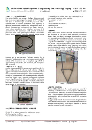
In this project PID controller is used to set the required
temperature to change the state of plastic from solid to semi
solid and band heater are used to heat up the hollow tube
which contain shredded plastic. First PID controller and
band heaters are connected to the power supply through a
MCB with the help of wires.
The band heaters are connected to the controller via a Solid
State Relay which acts as a switch to turn on and off the
supply to the band heaters by which the temperature is
controlled. Controller takes temperature input from the
thermocouple which is in contact with the hollow tube and
continuously reads the temperature of tube.
As power supply is switched on, we have to set the required
temperature in PID controller and then band heaters will
start heating up and then heat is transferred by conduction
to the barrels which contain the shredded plastic. As
temperature increase plastic changes its state from solid to
semisolid.
As plastic changes its state from solid to semi solid we inject
the semi-solid plastic through the nozzle into a die with help
of solid rod which acts as a plunger. The plastic which gets
injected into the die takes shape of the cavity which is shape
of our final products.
3. CONSTRUCTIONAL PARTS OF MACHINE
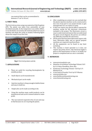
3.1 PID CONTROLLER
PID controller is a control loop feedback mechanism
commonly used in industrial control system. The combined
operation of these threecontrollersgivescontrol strategy for
process control. PID controller manipulates the process
variables like temperature in this case.
Fig. 3.1 PID controller
3.2 BAND HEATERS
Band heaters provide countless solution for cylindrical
surface heating applications. Band heaters are most widely
used heater because of their versatile design and rugged
construction characteristics. Band heaters are designed to
clamp to an exterior or interior cylindrical surface. Band
heaters often have higher watt densities allowing fast heat-
up and high operating temperatures. They generally include
clamp assemblies making installation easy.Bandheatersare
used for injection moldingbarrelsandnozzles,extrusionand
molding presses, pipe heating, heat treating and autoclaves,
food industry and other applications.
Fig. 3.2 Band heaters in various Sizes](https://image.slidesharecdn.com/irjet-v6i31027-190926092244/85/IRJET-Plastic-Injection-Moulding-Machine-2-320.jpg)

This document describes the development of a small plastic injection moulding machine for producing small plastic articles in small-scale industries. It discusses the design, construction, and testing of the machine. The machine is capable of injecting molten resins into a closed, cooled mould to produce plastic products. The design concept, operation, and assembly of component parts are covered. The document also provides details on the working principle of plastic injection moulding, including the various constructional parts of the machine like the PID controller, band heaters, thermocouple, and solid state relay. It discusses the assembly procedure and includes calculations and results from the first trial using polypropylene plastic.


