Downloaded 303 times

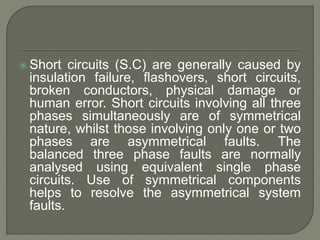

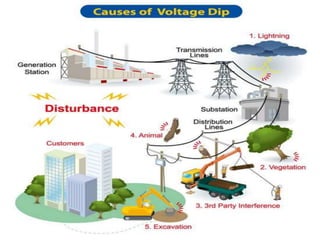
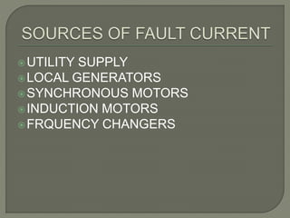
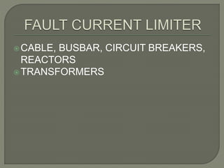
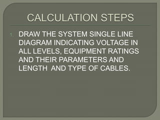

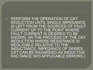
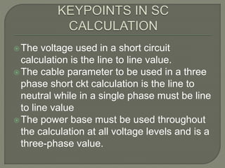
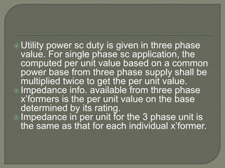
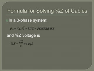
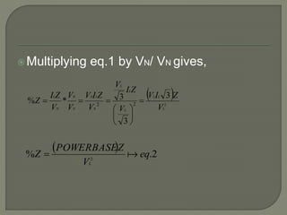
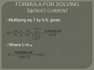
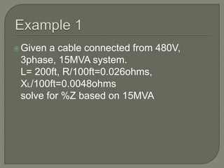
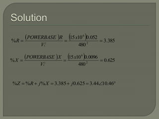
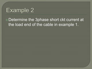
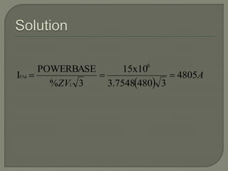


This document discusses short circuit calculations for electrical systems. It explains that short circuits can be caused by insulation failures, flashovers, physical damage or human error. Symmetrical and asymmetrical faults are described. Short circuit calculations should be performed at protective devices to determine device ratings and settings, cable sizes, and motor starting capabilities. A 6-step process for short circuit calculations is outlined, involving drawing diagrams, applying a power base, calculating impedances, and determining fault currents. Equations for converting three-phase values to single-phase are provided. An example cable calculation and fault current determination is shown.


