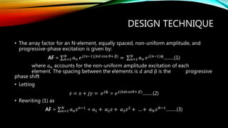
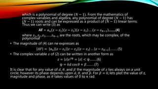
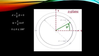
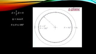
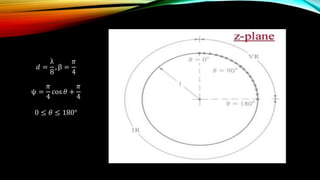
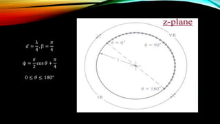
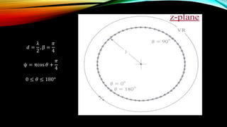
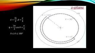
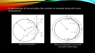
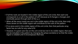
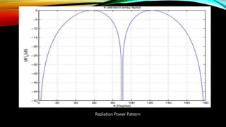
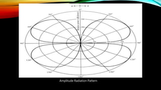
The document discusses the Schelkunoff polynomial method for antenna synthesis. It involves designing an antenna array to produce a desired radiation pattern with nulls in specific directions. The method models the array factor as a polynomial and solves for the roots, which correspond to null locations. Array coefficients are then determined to produce the required roots within the visible region of the unit circle based on the element spacing and progressive phase shifts. As an example, a 4 element linear array is designed with nulls at 0, 90, and 180 degrees.
Hello everyone. This is a short presentation on path loss and shadowing. I have not covered all the topics but a brief idea is given on path loss and wireless channel propagation models.
Hope you find it useful.
Thanks
Broadside Array vs end-fire array
Higher directivity.
Provide increased directivity in
elevation and azimuth planes.
Generally used for reception.
Impedance match difficulty in
high power transmissions.
Variants are:
Horizontal Array of Dipoles
RCA Fishborne Antenna
Series Phase Array
Deterministic MIMO Channel Capacity
• CSI is Known to the Transmitter Side
• CSI is Not Available at the Transmitter Side
Channel Capacity of Random MIMO Channels
An antenna array (or array antenna) is a set of multiple connected antennas which work together as a single antenna, to transmit or receive radio waves. The individual antenna elements are connected to a single receiver or transmitter by feedlines that feed the power to the elements in a specific phase relationship. The radio waves radiated by each individual antenna combine and superpose, adding together (interfering constructively) to enhance the power radiated in desired directions, and cancelling (interfering destructively) to reduce the power radiated in other directions. Similarly, when used for receiving, the separate radio frequency currents from the individual antennas combine in the receiver with the correct phase relationship to enhance signals received from the desired directions and cancel signals from undesired directions.
Circular antenna array has gained immense
popularity in the field of communications nowadays. It has
proved to be a better alternative over other types of antenna
array configuration due to its all-azimuth scan capability,
and a beam pattern which can be kept invariant. This paper is
basically concerned with the thinning of a large multiple
concentric circular ring arrays of uniformly excited isotropic
antennas based on Improved Particle Swarm Optimization
(IPSO) method. In this paper a 9 ringed Concentric Circular
Antenna Array (CCAA) with central element feeding is
considered. The computational results show that the number
of antenna array elements can be brought down from 279 to
147 with simultaneous reduction in Side Lobe Level of about
20 dB with a fixed half power beamwidth.
Linear Antenna Array synthesis with Decreasing Sidelobe and Narrow BeamwidthIDES Editor
Synthesizing arrays with low sidelobe and pencil
beam radiation profile is under investigation for decades. A
variety of array structures are available, but the simplest and
useful structure is that of a linear array. Here, two basic
symmetric Linear Antenna Array structures are assumed. The
required array structure is assumed to provide low sidelobe
and pencil beam profile. Departure from a uniformity in
current and location profile has shown quiet appreciable
improvement in the radiation pattern. The simulations are
carried out using Differential Evolution Algorithm employing
Best of Random mutation strategy (DEBoR).
15 Criteria for Working Remotely for the Aspiring Digital NomadLibby Tucker
Lessons learned as a nomadic traveler on the road. The 15 "mobility criteria" that are necessities to lead a digital nomad lifestyle. To live and work remotely, there are certain things you cannot be without. The mobility criteria are the basics so you can get up and go!
To learn more about the mobility criteria, check out this post on LiveWorkAnywhere
http://liveworkanywhere.com/remote-work/mobility-criteria
This module enables you to wireless transmit & receive serial data. It is a drop in replacement for wired serial connections allowing transparent two way data communication. You can simply use it for serial port replacement to establish connection between MCU or embedded project and PC for data transfer. This board operates on 5V and has LED indication and 3V regulator.
I think my presentation should covers almost all portition of topic android technology.......this will help u very much....
THANKS TO MY BELOVED FRIENDS OF IHRD CAS kaduthuruthy.....
by,,,,
MEBIN MATHEW
ME creations
An array antenna is a very interesting concept to control antenna radiation patterns. By using properly designed array elements, we can design a high gain or beam steering antenna very easily.
The Gesture Recognition Technology is rapidly growing technology and this PPT describes about the working of gesture recognition technology,the sub fields in it, its applications and the challenges it faces.
This Chapter is part of previous published ch.1 and ch.3 and its use for undergraduate students in physics department. also, you can use it for mathematical and Statistical courses and for those experimental courses of data fitting.
Chapter 6 Control systems analysis and design by the root-locus method. From the book (Ogata Modern Control Engineering 5th).
6-1 introduction.
6-2 Root locus plots.
6-5 root locus approach to control-system design.
Avionics 738 Adaptive Filtering at Air University PAC Campus by Dr. Bilal A. Siddiqui in Spring 2018. This lecture covers background material for the course.
This presentation gives an information about: photoelasticity, covering syllabus of Unit-3, of Experimental stress analysis subject for BE course under Visvesvaraya Technological University (VTU), Belgaum.
Similar to Schelkunoff Polynomial Method for Antenna Synthesis (20)
Welcome to WIPAC Monthly the magazine brought to you by the LinkedIn Group Water Industry Process Automation & Control.
In this month's edition, along with this month's industry news to celebrate the 13 years since the group was created we have articles including
A case study of the used of Advanced Process Control at the Wastewater Treatment works at Lleida in Spain
A look back on an article on smart wastewater networks in order to see how the industry has measured up in the interim around the adoption of Digital Transformation in the Water Industry.
Cosmetic shop management system project report.pdfKamal Acharya
Buying new cosmetic products is difficult. It can even be scary for those who have sensitive skin and are prone to skin trouble. The information needed to alleviate this problem is on the back of each product, but it's thought to interpret those ingredient lists unless you have a background in chemistry.
Instead of buying and hoping for the best, we can use data science to help us predict which products may be good fits for us. It includes various function programs to do the above mentioned tasks.
Data file handling has been effectively used in the program.
The automated cosmetic shop management system should deal with the automation of general workflow and administration process of the shop. The main processes of the system focus on customer's request where the system is able to search the most appropriate products and deliver it to the customers. It should help the employees to quickly identify the list of cosmetic product that have reached the minimum quantity and also keep a track of expired date for each cosmetic product. It should help the employees to find the rack number in which the product is placed.It is also Faster and more efficient way.
Student information management system project report ii.pdfKamal Acharya
Our project explains about the student management. This project mainly explains the various actions related to student details. This project shows some ease in adding, editing and deleting the student details. It also provides a less time consuming process for viewing, adding, editing and deleting the marks of the students.
Explore the innovative world of trenchless pipe repair with our comprehensive guide, "The Benefits and Techniques of Trenchless Pipe Repair." This document delves into the modern methods of repairing underground pipes without the need for extensive excavation, highlighting the numerous advantages and the latest techniques used in the industry.
Learn about the cost savings, reduced environmental impact, and minimal disruption associated with trenchless technology. Discover detailed explanations of popular techniques such as pipe bursting, cured-in-place pipe (CIPP) lining, and directional drilling. Understand how these methods can be applied to various types of infrastructure, from residential plumbing to large-scale municipal systems.
Ideal for homeowners, contractors, engineers, and anyone interested in modern plumbing solutions, this guide provides valuable insights into why trenchless pipe repair is becoming the preferred choice for pipe rehabilitation. Stay informed about the latest advancements and best practices in the field.
CFD Simulation of By-pass Flow in a HRSG module by R&R Consult.pptxR&R Consult
CFD analysis is incredibly effective at solving mysteries and improving the performance of complex systems!
Here's a great example: At a large natural gas-fired power plant, where they use waste heat to generate steam and energy, they were puzzled that their boiler wasn't producing as much steam as expected.
R&R and Tetra Engineering Group Inc. were asked to solve the issue with reduced steam production.
An inspection had shown that a significant amount of hot flue gas was bypassing the boiler tubes, where the heat was supposed to be transferred.
R&R Consult conducted a CFD analysis, which revealed that 6.3% of the flue gas was bypassing the boiler tubes without transferring heat. The analysis also showed that the flue gas was instead being directed along the sides of the boiler and between the modules that were supposed to capture the heat. This was the cause of the reduced performance.
Based on our results, Tetra Engineering installed covering plates to reduce the bypass flow. This improved the boiler's performance and increased electricity production.
It is always satisfying when we can help solve complex challenges like this. Do your systems also need a check-up or optimization? Give us a call!
Work done in cooperation with James Malloy and David Moelling from Tetra Engineering.
More examples of our work https://www.r-r-consult.dk/en/cases-en/
Courier management system project report.pdfKamal Acharya
It is now-a-days very important for the people to send or receive articles like imported furniture, electronic items, gifts, business goods and the like. People depend vastly on different transport systems which mostly use the manual way of receiving and delivering the articles. There is no way to track the articles till they are received and there is no way to let the customer know what happened in transit, once he booked some articles. In such a situation, we need a system which completely computerizes the cargo activities including time to time tracking of the articles sent. This need is fulfilled by Courier Management System software which is online software for the cargo management people that enables them to receive the goods from a source and send them to a required destination and track their status from time to time.
Hybrid optimization of pumped hydro system and solar- Engr. Abdul-Azeez.pdffxintegritypublishin
Advancements in technology unveil a myriad of electrical and electronic breakthroughs geared towards efficiently harnessing limited resources to meet human energy demands. The optimization of hybrid solar PV panels and pumped hydro energy supply systems plays a pivotal role in utilizing natural resources effectively. This initiative not only benefits humanity but also fosters environmental sustainability. The study investigated the design optimization of these hybrid systems, focusing on understanding solar radiation patterns, identifying geographical influences on solar radiation, formulating a mathematical model for system optimization, and determining the optimal configuration of PV panels and pumped hydro storage. Through a comparative analysis approach and eight weeks of data collection, the study addressed key research questions related to solar radiation patterns and optimal system design. The findings highlighted regions with heightened solar radiation levels, showcasing substantial potential for power generation and emphasizing the system's efficiency. Optimizing system design significantly boosted power generation, promoted renewable energy utilization, and enhanced energy storage capacity. The study underscored the benefits of optimizing hybrid solar PV panels and pumped hydro energy supply systems for sustainable energy usage. Optimizing the design of solar PV panels and pumped hydro energy supply systems as examined across diverse climatic conditions in a developing country, not only enhances power generation but also improves the integration of renewable energy sources and boosts energy storage capacities, particularly beneficial for less economically prosperous regions. Additionally, the study provides valuable insights for advancing energy research in economically viable areas. Recommendations included conducting site-specific assessments, utilizing advanced modeling tools, implementing regular maintenance protocols, and enhancing communication among system components.
Democratizing Fuzzing at Scale by Abhishek Aryaabh.arya
Presented at NUS: Fuzzing and Software Security Summer School 2024
This keynote talks about the democratization of fuzzing at scale, highlighting the collaboration between open source communities, academia, and industry to advance the field of fuzzing. It delves into the history of fuzzing, the development of scalable fuzzing platforms, and the empowerment of community-driven research. The talk will further discuss recent advancements leveraging AI/ML and offer insights into the future evolution of the fuzzing landscape.
Final project report on grocery store management system..pdfKamal Acharya
In today’s fast-changing business environment, it’s extremely important to be able to respond to client needs in the most effective and timely manner. If your customers wish to see your business online and have instant access to your products or services.
Online Grocery Store is an e-commerce website, which retails various grocery products. This project allows viewing various products available enables registered users to purchase desired products instantly using Paytm, UPI payment processor (Instant Pay) and also can place order by using Cash on Delivery (Pay Later) option. This project provides an easy access to Administrators and Managers to view orders placed using Pay Later and Instant Pay options.
In order to develop an e-commerce website, a number of Technologies must be studied and understood. These include multi-tiered architecture, server and client-side scripting techniques, implementation technologies, programming language (such as PHP, HTML, CSS, JavaScript) and MySQL relational databases. This is a project with the objective to develop a basic website where a consumer is provided with a shopping cart website and also to know about the technologies used to develop such a website.
This document will discuss each of the underlying technologies to create and implement an e- commerce website.
2. OVERVIEW
• What is antenna synthesis?
• Steps involved in antenna synthesis
• Various methods of antenna synthesis
• Schelkunoff Polynomial Method
• Design Technique
• Design Steps
• Design example
3. ANTENNA SYNTHESIS
• In general, analysis of antenna is done by selecting a particular antenna model and
its various radiation characteristics such as pattern, directivity, impedance,
beamwidth, efficiency, polarization, and bandwidth are analysed using standard
procedures usually by specifying its current distribution.
• In practice, it is often necessary to design an antenna system that will yield desired
radiation characteristics. Common requests to design an antenna are for pattern to
exhibit a desired distribution, beamwidth, size of side lobes, minor lobes, etc.
• The task, in general, is to find not only the antenna configuration but also its
geometrical dimensions and excitation distribution.
4. • The designed system should yield, either exactly or approximately, an acceptable
radiation pattern.
• This method of design is known as antenna synthesis.
5. ANTENNA SYNTHESIS STEPS
• Antenna synthesis usually requires that first an approximate analytical model is
chosen to represent, either exactly or approximately, the desired pattern.
• The second step is to match the analytical model to a physical antenna model.
6. ANTENNA SYNTHESIS METHODS
Antenna synthesis can be classified into three categories:
One group requires that the antenna patterns possess nulls in desired directions.
Schelkunoff Polynomial Method
Another category requires that the patterns exhibit a desired distribution in the entire visible
region. This is referred to as beam shaping.
Fourier Transform Method
Woodward Lawson Method
Third group includes techniques that produce patterns with narrow beams and low side
lobes.
Binomial Method
Dolph-Tschebscheff Method
Taylor line-source
7. SCHELKUNOFF POLYNOMIAL
METHOD
• Schelkunoff polynomial method is conductive to the synthesis of arrays whose
patterns possess nulls in desired directions.
• To complete the design, this method requires information on the number of nulls
and their locations.
• The number of elements and their excitation coefficients are then derived.
8. DESIGN TECHNIQUE
• The array factor for an N-element, equally spaced, non-uniform amplitude, and
progressive-phase excitation is given by:
AF = 𝑛=1
𝑁
𝑎 𝑛 𝑒 𝑗(𝑛−1)(𝑘𝑑 cos θ+ β) = 𝑛=1
𝑁
𝑎 𝑛 𝑒 𝑗(𝑛−1)ψ.........(1)
where 𝑎 𝑛 accounts for the non-uniform amplitude excitation of each
element. The spacing between the elements is 𝑑 and β is the progressive
phase shift
• Letting
𝑧 = 𝑥 + 𝑗𝑦 = 𝑒 𝑗ψ = 𝑒 𝑗(𝑘𝑑𝑐𝑜𝑠𝜃+ 𝛽).........(2)
• Rewriting (1) as
AF = 𝑛=1
𝑁
𝑎 𝑛 𝑧 𝑛−1
= 𝑎1 + 𝑎2 𝑧 + 𝑎3 𝑧2
+ … + 𝑎 𝑁 𝑧 𝑁−1
…......(3)
9. which is a polynomial of degree (𝑁 − 1). From the mathematics of
complex variables and algebra, any polynomial of degree 𝑁 − 1 has
(𝑁 − 1) roots and can be expressed as a product of 𝑁 − 1 linear terms.
Thus we can write (3) as
AF = 𝑎 𝑛 𝑧 − 𝑧1 𝑧 − 𝑧2 𝑧 − 𝑧3 … 𝑧 − 𝑧 𝑁−1 .........(4)
where 𝑧1, 𝑧2, 𝑧3, … , 𝑧 𝑁−1 are the roots, which may be complex, of the
polynomial
• The magnitude of (4) can ne expresses as
𝐴𝐹 = 𝑎 𝑛 𝑧 − 𝑧1 𝑧 − 𝑧2 𝑧 − 𝑧3 … 𝑧 − 𝑧 𝑁−1 ………(5)
• The complex variable 𝑧 of (2) can be written in another form as
𝑧 = 𝑧 𝑒 𝑗ψ
= 𝑧 < ψ.........(6)
ψ = 𝑘𝑑 cos 𝜃 + 𝛽………(7)
It is clear that for any value of 𝑑, 𝜃, and 𝛽 the magnitude of 𝑧 lies always on a unit
circle; however its phase depends upon 𝑑, 𝜃, and 𝛽. For 𝛽 = 0, lets plot the value of z,
magnitude and phase, as 𝜃 takes values of 0 to π rad.
14. • For all the physically observable angles of θ, only exists over a part of the circle.
• Any values of z outside that arc are not realizable by any physical observation angle
θ for the spacing.
• The realizable part of the circle is referred to as the visible region and the remaining
as invisible region.
• It is obvious that the visible region can be extended by increasing the spacing
between the elements.
• It requires a spacing of at least λ
2 to encompass, at least once, the entire circle. Any
spacing greater than λ
2 leads to multiple values of z.
15. • To demonstrate the versatility of the arrays, let us plot the values of z for the same
spacings but with a 𝛽 = 𝜋
4.
20. • A comparison between the corresponding figures indicates that the overall visible
region for each spacing has not changed but its relative position on the unit circle
has rotated counter clockwise by an amount equal to β.
• We can conclude that the overall extent of the visible region can be controlled by
the spacing between the elements and its relative position on the unit circle by the
progressive phase excitation of the elements.
• These two can be used effectively in the design of the array factors.
21. • To demonstrate all the principles, lets consider an example along with some
computations.
Roots of array factor Roots of array factor on unit circle
and within visible region
22. • If all the roots are located in the visible region of the unit circle, then each one
corresponds to a null in the pattern of 𝐴𝐹 because as θ changes z changes and
eventually passes through each of the 𝑧 𝑛’s.
• When all the zeros (roots) are not in the visible region of the unit circle, then only
those zeroes on the visible region will contribute to the nulls of the pattern.
• If no zeros exist in the visible region of the unit circle, then that particular array
factor has no nulls for any value of θ.
• However, if a given zero lies on the unit circle but not in its visible region, that zero
can be included in the pattern by changing the phase excitation 𝛽 so that the visible
region is rotated until it encompasses that root.
23. DESIGN STEPS
1. For given spacing, phase shift and null locations plot the visible region.
2. Find the roots of AF corresponding to the desired null locations.
3. Check whether the roots lie on the unit circle within the visible region.
4. Find the array factor with respect to the roots present on the unit circle within the
visible region.
5. Find array coefficients
24. EXAMPLE
• Design a linear array with a spacing between the elements of 𝑑 = λ
4 such that it has
zeros at 𝜃 = 0°, 90°, 𝑎𝑛𝑑 180°. Determine the number of elements, their excitation,
and plot the derived pattern.
ψ =
2𝜋
λ
× 𝑑 cos 𝜃 + 𝛽
𝑧 = 1 < ψ
𝐴𝐹 = 𝑧 − 𝑧1 𝑧 − 𝑧2 𝑧 − 𝑧3 … (𝑧 − 𝑧 𝑁−1)
Array Coefficients 𝑎1, 𝑎2, 𝑎3, … , 𝑎 𝑁