Downloaded 232 times

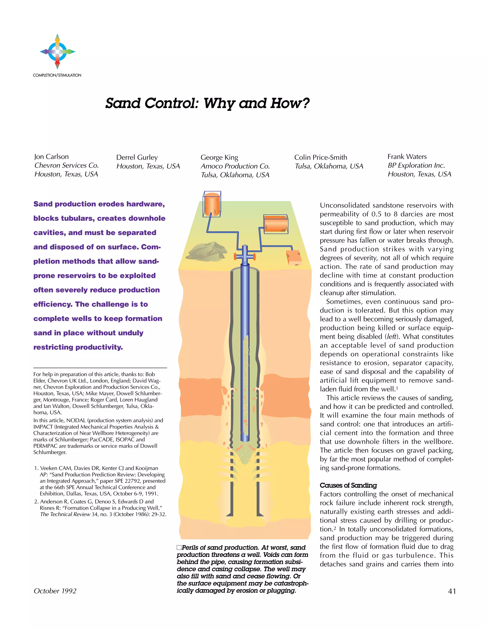
![Resin-Coated Gravel Without Screens:
Resin-coated gravel may be used as a
downhole filter without installing a screen.
The gravel is circulated into position as a
slurry, either inside casing or open hole and
then squeezed to form a plug across the
production zone. Adjacent particles are
bonded together by the resin, strengthening
the pack.
In cased hole, the plug may be com-
pletely drilled out to leave gravel-filled per-
forations. Alternatively, the pack may be
drilled out to the top of the perforations/
open hole so that hydrocarbons are pro-
duced through the pack. A narrow hole can
be drilled through the pack to provide a
conduit to reduce drawdown through the
pack. This can be achieved using coiled
tubing if a conventional rig is not available.
Resin-coated gravel has the advantage of
needing no special hardware. But the pack
creates significant additional drawdown that
may affect productivity. If the drillout tech-
nique is employed to reduce drawdown, all
perforations must be evenly packed and the
resulting pack may be fragile. Complete
coverage of intervals longer than about 20 ft
[6 m] is difficult to achieve. The technique
represents about 5% of sand-control treat-
ments, mainly concentrated on low-cost
onshore markets.
Slotted Liners and Prepacked Screens: Slot-
ted pipes, screens and prepacked screens
offer the lowest-cost downhole filtering.
Slotted liners have the largest holes, wire-
wrapped screens have smaller openings,
while screens prepacked with resin-coated
sand offer the finest filtering. Each type can
be run as part of the completion string and
are particularly suited for high-angle wells,
which cannot be easily completed other-
wise (see “Screening Horizontal Wells,”
page 45).
Slots are typically sized to cause bridging
of the largest 10% of the formation particles,
filling the annulus between the screen and
casing, or open hole, with formation sand
creating a filter for remaining particles.
However, production can be restricted by
this relatively low-permeability, sand-
packed annulus. Also, production of even a
small amount of fines can plug many
screens, particularly prepacked screens,
within a few hours of installation.
Slotted liners and screens are best suited
to formations that are friable rather than
completely unconsolidated. They are mostly
used in California, USA, and some Gulf of
Mexico, USA fields where permeabilities
are greater than 1 darcy. Slotted liners and
prepacked screens are used in only about
5% of sand-control completions.
Finally, rocks either fail in tension when
they are pulled apart or they fail in shear
when they are crushed. IMPACT analysis
enables the interpreter to pick the most
likely failure mechanism. From this, the
program predicts sanding potential.
Completion Options
Once it has been established that at planned
production rates sand is likely to be pro-
duced, the next step is to choose a comple-
tion strategy to limit sanding. A first option
is to treat the well with “tender loving care,”
minimizing shocks to the reservoir by
changing drawdown and production rate
slowly and in small increments. Production
rate may be reduced to ensure that draw-
down is below the the point at which the
formation grains become detached. More
subtly, selective perforation may avoid
zones where sanding is most likely. How-
ever, both options reduce production, which
may adversely affect field economics.9
The most popular options for completing
sand-prone reservoirs physically restrain
sand movement. The four main classes of
completion are resin injection, slotted liners
and prepacked screens, resin-coated gravel
without screens and gravel packing.
Resin Injection: To cement the sand grains
in situ, a resin is injected into the formation,
generally through perforations, and then
flushed with a catalyst. Most commercially
available systems employ phenolic, furan or
epoxy resins. They bind rock particles
together creating a stable matrix of perme-
able, consolidated grains around the casing.
Clay concentration can hinder the effec-
tiveness of the consolidation process, so a
clay stabilizer is often used as a preflush.
Residual water may also interfere with the
development of consolidation strength and
may necessitate use of increased quantities
of resin.10 The quantity of resin injected is a
compromise between enhancing consolida-
tion strength and reducing permeability. For
example, if an 8-darcy unconsolidated sand
is resin treated to give a compressive
strength of up to 3300 psi, permeability may
be reduced by 25% and productivity cut by
up to 10%.11
Further, sand production will not be pre-
vented if chemical injection is uneven and
some exposed sand is uncoated. Because of
this, the technique tends to be reserved for
short intervals, up to 10 to 15 ft [3 to 4 m].
Complete coverage of larger zones is diffi-
cult unless selective placement tools are
used. Although resin consolidation is used
successfully, it accounts for no more than
about 10% of sand-control completions.
43October 1992
3. Morita N and Boyd PA: “Typical Sand Production
Problems: Case Studies and Strategies for Sand Con-
trol,” paper SPE 22739, presented at the 66th SPE
Annual Technical Conference and Exhibition, Dallas,
Texas, USA, October 6-9, 1991.
4. Winchester PH: “The Cardinal Rules of Gravel Pack-
ing to Avoid Formation Damage,” paper SPE 19476,
presented at the SPE Asia-Pacific Conference, Sydney,
Australia, September 13-15, 1989.
5. Bratli R K and Risnes R: “Stability and Failure of Sand
Arches,” paper SPE 8427, presented at the 54th SPE
Annual Technical Conference and Exhibition, Las
Vegas, Nevada, USA, September 23-26, 1979.
Tippie DB and Kohlhaas CA: “Variation of Skin Dam-
age with Flow Rate Associated With Sand Flow or Sta-
bility in Unconsolidated-Sand Reservoirs,” paper SPE
4886, presented at the 44th SPE Annual California
Regional Meeting, San Francisco, California, USA,
April 4-5, 1974.
Morita N, Whitfill DL, Massie I and Knudsen TW:
“Realistic Sand-Production Prediction: Numerical
Approach,” SPE Production Engineering 4, no. 1
(February 1989): 15-24.
6. Deruyck B, Ehlig-Economides C and Joseph J: “Testing
Design and Analysis,” Oilfield Review 4, no. 2 (April
1992): 28-45.
7. Morita and Boyd, reference 3.
8. Santarelli FJ, Ouadfel H and Zundel JP: “Optimizing
the Completion Procedure to Minimize Sand Produc-
tion Risk,” paper SPE 22797, presented at the 66th
SPE Annual Technical Conference and Exhibition,
Dallas, Texas, USA, October 6-9, 1991.
Tixier MP, Loveless GW and Anderson RA: “Estima-
tion of Formation Strength From the Mechanical Prop-
erties Log,” Journal of Petroleum Technology 27
(March 1975): 283-293.
Stein N: “Determine Properties of Friable Formation
Sands,” World Oil 206, no. 3 (March 1988): 33-37.
9. Massie I, Nygaard O and Morita N: “Gullfaks Subsea
Wells: An Operator’s Implementation of a New Sand
Production Prediction Model,” paper SPE 16893,
presented at the 62nd SPE Annual Technical Confer-
ence and Exhibition, Dallas, Texas, USA, September
27-30, 1987.
Unneland T and Waage RI: “Experience and Evalua-
tion of Production Through High-Rate Gravel-
Packed Oil Wells, Gullfaks Field, North Sea,” paper
SPE 22795, presented at the 66th SPE Annual Tech-
nical Conference and Exhibition, Dallas, Texas,
USA, October 6-9, 1991.
10. Pelgrom J and Wilson RA: “Completion Develop-
ments in Unconsolidated Oil-Rim Reservoirs,” paper
OSEA 90123, presented at the Eighth Offshore South
East Asia Conference, Singapore, December 4-7,
1990.
11. Davies, DR: “Applications of Polymers in Sand Con-
trol,” paper presented at Use of Polymers in Drilling
and Oilfield Fluids, organized by the Offshore Engi-
neering Group of the Plastics and Rubber Institute,
London, England, December 9, 1991.](https://image.slidesharecdn.com/sandcontrolwhyandhow-160112161331/85/Sand-control-why-and-how-3-320.jpg)
![Studies generally conclude that the most effec-
tive technique for excluding sand in high-angle
and horizontal wells is gravel packing.1 Although
there have been some notable operational suc-
cesses, the technical complexities of high-angle
gravel packing and its relatively high cost mean
that alternative techniques are often considered.2
A case in point in the UK North Sea is the Alba
field which is operated by Chevron UK Ltd. The
350-ft [107-m] thick Eocene sand reservoir is
completely unconsolidated and currently under
development. Most of the field’s production wells
will have horizontal sections of up to 2600 ft.
When the field comes onstream, each well will
produce up to 30,000 B/D using electric sub-
mersible pumps.
Water breakthrough is expected after only two
months of production and 40% water cut is
expected by the end of the first year. Early water
production will exacerbate sand production by
reducing the interstitial tension between sand
grains, making sand control a major factor of the
development plan.
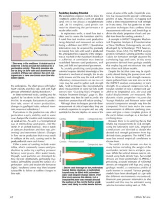
Initial plans called for horizontal cased-hole
gravel packs. However, the company continued to
study alternative solutions and concluded that
prepacked screens could successfully keep sand
at bay (right). Prepacked screens cost signifi-
cantly less than gravel packs and are simpler to
install. What convinced Chevron was not the cost
but the increased internal diameter (ID) afforded
by the prepacked screens—4.4 in. [11 cm] as
opposed to the 2.9 in. [7.4 cm] of the planned
gravel packs.
Larger ID reduces the pressure drop along the
horizontal length of the well, leading to a better
inflow distribution—when the pressure drop is
high, production from the near end of the well-
bore is favored. In the field’s conventionally devi-
ated wells, where pressure differential will not
significantly affect inflow performance, Chevron
will employ conventional gravel packs.
The prepacked screens will comprise 5-in. pipe
wrapped with two layers of screen with an out-
side diameter of 6 5/8-in. [16.8-cm]. Between the
screen will be a 1/2-in. [1.3 -cm] thick pack of
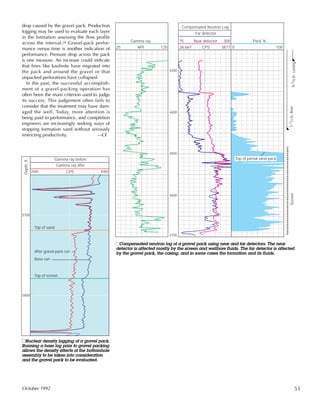
nHorizontal well com-
pletion design for the
Alba field.
1. Forrest JK: “Horizontal Gravel Packing Studies in a Full-
Scale Model Wellbore,” paper SPE 20681, presented at
the 65th SPE Annual Technical Conference and Exhibition,
New Orleans, Louisiana, USA, September 23-26, 1990.
Sparlin DD and Hagen WH Jr: “Gravel Packing Horizontal
and High-Angle Wells,” World Oil 213, no. 3 (March
1992): 45-49.
2. Wilson DJ and Barrilleaux MF: “Completion Design and
Operational Considerations for Multizone Gravel Packs in
Deep, High-Angle Wells,” paper OTC 6751, presented at
the 23rd Annual Offshore Technology Conference, Hous-
ton, Texas, USA, May 6-9, 1991.
Zaleski TE Jr: “Sand-Control Alternatives for Horizontal
Wells,” Journal of Petroleum Technology 43 (May 1991):
509-511.
430-ft water depth
30-in. casing, 800 ft MD/TVD
20-in. casing, 1200 ft MD/TVD
103
/4-in. casing, 1500 ft MD/TVD
133
/8-in. casing set between: 2500 ft -4000 ft MD
2500 ft -3500 ft TVD
95
/8-in. casing set ± 200 ft into horizontal:
7000 ft–9500 ft MD
6200 ft–6400 ft TVD
81
/2-in. open hole
with prepacked screen
1000 ft–2600 ft
Eocene
45October 1992
resin-coated gravel. The screens will be inserted
into open hole, 8 1/2-in. [22-cm] diameter, so
there is a likelihood of sand sloughing around the
screens. Chevron tested the effects of sloughing
on permeability around the wellbore. At worst, it
reduced permeability from 3 darcies to 1, not
enough to significantly limit production.
On the downside, the longevity of the screens
is uncertain and there is a lack of zonal isolation
afforded by an openhole completion. In an effort
to combat this, blank sections with internal seals
will be deployed every 400 ft [120 m] of screen,
allowing fluids to be spotted, and plugs and
straddle packers to be set using coiled tubing.
Screening Horizontal Wells](https://image.slidesharecdn.com/sandcontrolwhyandhow-160112161331/85/Sand-control-why-and-how-5-320.jpg)
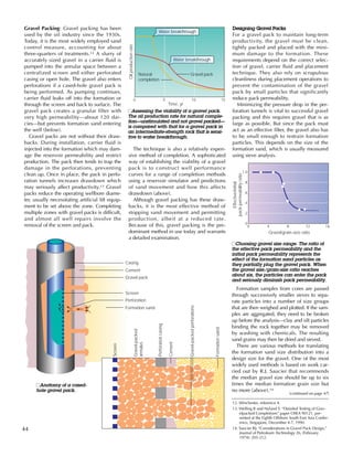
![nThe four positions for gravel packing. In
squeeze position, the service tool seals into
the packer and does not allow circulation.
When slurry is pumped in this mode, all
the carrier fluid leaks off into the formation.
In upper circulating position, slurry is
pumped down the casing-screen annulus
and the carrier fluid can be squeezed
through any part of the screen, into the
washpipe at the bottom of the service tool
and back to surface via the service tool-
casing annulus above the packer.
In lower circulating position, slurry is
also pumped down the casing-screen
annulus, but returns of carrier fluid have to
pass through the bottom of the pack where
the washpipe is sealed into the lower tell-
tale—a sealbore with a short piece of
screen below—located below the main
screen. The aim is try to maintain flow in
the casing-screen annulus and ensure that
there is not a void in the gravel in the
annulus below the screen.
However, if the interval being packed is
longer than 25 ft [8 m], backpressure on
the fluid may cause the fluid to bypass the
pack and pass down the well via the
screen/washpipe annulus, which may
encourage bridging off higher up the well.
Reverse circulation involves pumping
fluid through the washpipe, up the screen/
washpipe annulus and back up to surface.
46 Oilfield Review
Service tool
Permanent-retrievable
packer
Ported housing
Sealbore housing
Locating collars
Blank pipe
Primary screen
‘O’ ring seal sub
Lower telltale
Sump packer
Seal unit
1. Squeeze position 3. Lower circulating position2. Upper circulating position 4. Reversing position](https://image.slidesharecdn.com/sandcontrolwhyandhow-160112161331/85/Sand-control-why-and-how-6-320.jpg)
![Recently, work by B.W. Hainey and J.C.
Troncoso of ARCO points to the possibility
of using larger gravel, offering higher pack
permeability.15 To explain this, Hainey and
Troncoso argue that in some cases formation
sand grains move as larger agglomerates
rather than as individual grains.16
Average grain size is not the only determi-
nant of gravel-pack permeability. The best
gravel-pack sands are round and evenly
sized. The most common way of estimating
roundness and sphericity is by examining
the gravel through a 10- to 20-power micro-
scope and comparing the shapes with a ref-
erence chart. Gravel-size distribution can be
monitored by sieve analysis.
The next decision facing the engineer is
whether the completion should be cased or
openhole. Openhole gravel packs have no
perforations and therefore offer the mini-
mum pressure drop across the pack. But
placement may be time-consuming. Care
must be taken to remove the filter cake
deposited on the formation by drilling fluid
and to avoid abrading the formation and
contaminating the gravel. Cased-hole gravel
packs present the additional challenge of
properly packing the perforations.
To check that a well is suitable for cased-
hole gravel packing, productivity may be
calculated using NODAL production system
analysis. This models the pressure drop as
reservoir fluid flows through the perforations
into the completion hardware to surface.
Pressure drop in perforation tunnels is a
major impediment to production and varies
with tunnel length, perforation area, pack
permeability, viscosity of the produced flu-
ids and reservoir pressure (see “Choosing a
Perforation Strategy,” page 54). The gravel
size range determines pack permeability—
the smaller the grains, the more the pack
restricts formation flow—and is fixed by the
size of the formation sand. Formation fluid
viscosity and reservoir pressure are also
fixed. To reduce pressure drop, inflow area
may be raised by increasing perforation
diameter and/or increasing the number of
perforations. If the well is perforated with
tubing-conveyed perforating (TCP), high
shot density guns, gravel packs can nearly
match the inflow performance of openhole
packs for many reservoirs. Pressure drop
may also be reduced by increasing the
diameter of casing in which the gravel pack
is to be placed. If sufficient inflow area can-
not be achieved through perforation, open-
hole completion is required.
Once the method of completion is
selected, the hardware may be chosen. At
its simplest, a packer and screen assembly
with a washpipe inside are usually run in
hole with a service tool. However, when
multiple zones are to be completed in
stages, the hardware becomes a complex
series of screens and packers.
The service tool is then used to set the
packer above the zone to be completed.
Thereafter, the positions of the service tool
in the packer and washpipe in the screen
assembly determine the flow direction of
fluids pumped downhole. Sophisticated sys-
tems have four positions: squeeze, upper
circulating, lower circulating and reverse
circulating and therefore allow single-trip
treatments (previous page).
In a single-trip gravel-pack treatment, the
perforation guns are fired and lowered into
the rathole. The perforations may be filled
with gravel with the packer in the squeeze
position and the annulus is filled with it in
either the upper or lower circulating posi-
tions. Excess gravel is then reversed out.
However, the hardware used in many
gravel-pack operations does not permit sin-
gle-trip operations. For a cased-hole gravel
pack, the TCP guns must be retrieved and
then the workstring must removed after
gravel packing so that the completion string
may be run. During these trips, the service
tool and the washpipe are withdrawn from
the packer, exposing the relatively high-per-
meability formation to the hydrostatic pres-
sure of the completion fluid above the
packer. This usually causes fluid to be lost
into the formation.
To reduce losses, particulate loss control
material (LCM) suspended in a viscous fluid
is commonly pumped downhole before
each trip. The LCM plugs the completion
fluid’s flow path into the formation. After the
trip, the LCM is removed. Common LCMs
include marble chips (calcium carbonate,
removable with acid), oil-soluble resins or
salt pills (see “Gravel Packing Forth Field
Exploration Wells,” next page).
Each time LCM is used, there is a danger
of incomplete removal damaging the reser-
voir. To avoid the need to pump LCM when
the washpipe and workstring are removed
from the packer, a flapper valve can be
employed below the packer. This valve is
capable of accommodating a large-diameter
washpipe to direct flow to the casing-screen
annulus. It closes after the service tool and
washpipe are removed, preventing comple-
tion fluid from passing through the pack and
into the permeable formation. When the
completion string is run, the flapper valve is
opened—either mechanically, with wireline
or using pressure.
Wire-wrapped screens are usually used to
retain the gravel. Selection of wire spacing
is not subject to any hard and fast rules, but
a common rule of thumb calls for the slots
to be 75% of the smallest gravel diameter.
Screen diameter depends on the inlet area,
the pack thickness and the ability to fish the
screen out of the hole. This normally leads
to using screens with at least 1-in. [2.5 cm]
annular clearance. Screens are normally
run 5 ft [1.5 m] above and below the pro-
ducing zone and centralized every 15 ft [5
m] to improve the chances of a consistent
gravel fill.
Transporting gravel into the perforations
and annulus is the next consideration.
Gravel can sometimes bridge off prema-
turely, leaving voids in the annulus. In verti-
cal wells, incomplete fill may be rectified
when pumping stops and gravel in the
annulus collapses into the voids. This ceases
to be the case in wells deviated more than
50°, where voids below a bridge are likely
to remain. Transport is a function of the sus-
pension properties of the fluid and the
energy required to move the slurry. Impor-
tant factors determining settling are pump
rate, the relative densities of the gravel and
the carrier fluid, gravel diameter and the
apparent viscosity of the fluid when
pumped downhole.17
There is also a relationship between
gravel concentration and carrier fluid vis-
cosity when it comes to “turning the corner”
in the annulus and entering perforations.
Fluid viscosity must increase if gravel con-
centration in the slurry increases, otherwise
the gravel will tend to sink to the bottom of
the well. Packing efficiency is also affected
by the rate the carrier fluid leaks off into the
formation. If leakoff is rapid, the gravel is
likely to be carried to the perforation tunnel-
formation interface and held there as the
fluid leaks off. If leakoff is slow, the gravel
has more time to settle and will not effec-
tively pack the perforations.
47October 1992
15. According to American Petroleum Institute recom-
mended practices (RP 58), the designation 40/60
indicates that not more than 2% of the gravel should
be smaller than the 40-mesh sieve and not more
than 0.1% should be larger than the 20-mesh sieve.
16. Hainey BW and Troncoso JC: “Frac-Pack: An Inno-
vative Stimulation and Sand Control Technique,”
paper SPE 23777, presented at the SPE International
Symposium on Formation Damage Control,
Lafayette, Louisiana, USA, February 26-27, 1992.
17. Gurley DG and Hudson TE: “Factors Affecting
Gravel Placement in Long Deviated Intervals,” paper
SPE 19400, presented at the SPE Formation Damage
Control Symposium, Lafayette, Louisiana, USA,
February 22-23, 1990.](https://image.slidesharecdn.com/sandcontrolwhyandhow-160112161331/85/Sand-control-why-and-how-7-320.jpg)
![There is no such thing as a typical gravelpack;
each is a complex combination of relatively sim-
ple operations. This example is based on a
gravel-packing procedure used on several verti-
cal appraisal wells in the Forth field in the UK
North Sea operated by BP Exploration. Forth, dis-
covered in 1986, has an Eocene reservoir com-
prising massive, clean sand located at a depth of
about 5500 ft [1675 m]. Permeability is 6 to 12
millidarcies and porosity is 35%.1
Cleanliness is fundamental to gravel packing
efficiency. Any contaminants that may plug the
gravel pack and decrease productivity must be
removed. In preparation for the gravel packing,
the mud pits were cleaned and the mud changed
to brine completion fluid. Tubulars were exter-
nally shot blasted, internally jetted and steam
cleaned before being run in hole. Because the
dope used to lubricate pipe joints is a serious
contaminant, it was applied sparingly to the pin
end only.
Cement for the production casing was dis-
placed with seawater. The cement scours the cas-
ing, but to further clean the wellbore, scrapers
were run and seawater circulated at high pump
rates. Cleanup pills of detergent, scouring pills
with gel spacers and flocculants were also circu-
lated. The well was then displaced to brine. Ini-
tial returns of seawater-contaminated brine were
discarded before the system was closed and sur-
face filters employed to reduce the maximum
particulate size to less than 2 microns [µm].
Solids in the brine were monitored to ensure that
there were fewer than 10 parts per million.
Perforation was carried out using tubing-con-
veyed perforating (TCP) guns with an underbal-
ance of about 300 psi. A short flow of 2 ft3/ft of
perforation was performed to remove debris. The
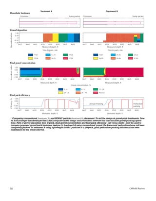
TCP guns were then dropped off. BP decided to
prepack the perforations with gravel prior to run-
ning the screen assembly. This strategy was used
to limit formation damage and prevent loss con-
trol material from entering the perforation tun-
nels (above).
Gravel in gelled carrier fluid was circulated
into place and then squeezed into the perfora-
tions. This was repeated two or three times to
ensure that all the perforations were packed. An
LCM pill of sodium chloride in xanthan gum and a
modified starch was then spotted across the
packed perforations to prevent loss of completion
fluid while the tubing was pulled.
A sump packer was set below the zone to be
completed and above the dropped TCP guns. The
main packer, service tool and screen assembly
were then run and the packer set.
The LCM pill was dissolved by circulating
unsaturated brine and the main gravel pack circu-
lated into place. A second LCM pill was then
spotted across the screen to allow recovery of the
service tool without losing completion fluid into
the formation (next page, left). The final comple-
tion hardware was run and the LCM dissolved.
1. Gilchrist JM and Gilchrist AL: “A Review of Gravel Pack-
ing in the Forth Field,” paper SPE 23128, presented at the
Offshore Europe Conference, Aberdeen, Scotland,
September 3-6, 1991.
48 Oilfield Review
Gravel slurry
Prepack gravel
Formation
Cement
Casing
Gun fish Settled excess gravel
Loss control material
Loss control material
pill
nPrepacking the perfo-
rations. Prepacking the
perforations prevents
loss control material from
entering the perforation
tunnels; this improves
subsequent cleanup and
reduces damage. Tub-
ing-conveyed perforating
guns were dropped,
gravel was bullheaded
into the perforations and
loss control material
spotted across the tun-
nel entrances.
Gravel Packing Forth Field Exploration Wells](https://image.slidesharecdn.com/sandcontrolwhyandhow-160112161331/85/Sand-control-why-and-how-8-320.jpg)
![nDissolving the loss control material and circulating
an annular gravel pack.
There is no industry consensus on govern-
ing choice of fluid viscosity and gravel con-
centration, but the following three combina-
tions are the most common:
•In conventional, circulating gravel packs,
most of the carrier fluid squeezed out of
the slurry is circulated back to surface.
The slurry usually has a low-viscosity car-
rier fluid of less than 50 centipoise (cp)
and ungelled water is a common carrier.
Gravel concentration can range from 0.25
to 15 lbm/gal depending on the carrier
fluid viscosity and company preference.
The technique is generally employed for
intervals of more than 50 ft [15 m] and
deviated holes up to horizontal. Fluid
leakoff is essential to ensure that perfora-
tions are packed, but excessive leakoff
may lead to bridging.
•High-density circulating gravel packs are
used for medium to long intervals—25 ft
[8 m] to more than 100 ft [30 m]. The
slurry usually has a viscosity of more than
50 cp and a gravel concentration of 7 to
15 lbm/gal.
•Squeeze packs, in which all the carrier
fluid leaks off into the formation, are used
for short intervals of less than 25 ft.
The conventional approach to controlling
settling—decreasing gravel concentration
and increasing carrier-fluid viscosity—has
drawbacks. To place an equivalent quantity
of gravel, more carrier fluid must be lost,
increasing the potential for formation dam-
age. However, increased viscosity slows the
rate of leakoff—a 250-cp fluid will leak off
more than six times slower than a 40-cp
fluid.18 Increasing carrier-fluid viscosity may
also increase formation damage.
Sometimes, in an effort to improve place-
ment, carrier-fluid viscosity and gravel con-
centration are both increased to create a
plug of slurry. But increased slurry viscosity
raises friction pressure and may increase the
possibility of bridging in the annulus.
Another way of reducing settling, helping
gravel to turn the corner and efficiently pack
perforations is to use a gravel and carrier
fluid of closely matched densities—not the
case when using conventional gravels or
low-density brines. For this purpose, Dowell
Schlumberger has developed ISOPAC low-
density, high-strength particles. Because set-
tling is not a major problem when the densi-
ties are matched, the pump rate can be
slowed, improving tightness of the pack and
increasing the time available to pack all the
perforations (below and next page). The
reduced viscosity increases the rate of
leakoff and reduces the potential for forma-
tion damage.
ISOPAC particles have been used in over
30 Gulf of Mexico and North Sea jobs since
introduction in 1991. The efficiency with
which perforations have been packed can-
not be measured directly. One indirect diag-
nostic method is based on the average vol-
ume of gravel placed per foot of interval
(ft3/ft). Rules of thumb derived from experi-
ence consider the placement efficiency of
about 0.25 ft3/ft of conventional gravel as
being satisfactory for intervals of less than
60 ft [18 m]. For longer intervals it is more
difficult to fill all the perforations equally
and, if the interval is 100 ft or so, an average
placement efficiency of only about 0.1 ft3/ft
49October 1992
Main gravel
pack screen
Tell tale screen
Washpipe bottom
‘O’ ring seal sub
Sump packer
Packer
Gravel pack
extension
with sliding sleeve
Crossover
Washpipe
Blank pipe
Logging reference
screen
Wireline reentry
guide
Sliding sleeve closed
18. Hudson TE and Martin JW: “Use of Low-Density,
Gravel-Pack Material Improves Placement Effi-
ciency (Part 2),” paper SPE 18227, presented at the
63rd SPE Annual Technical Conference and Exhibi-
tion, Houston, Texas, USA, October 2-5, 1988.
Bryant D, Hudson T and Hoover S: “The Use of
Low-Density Particles for Packing a Highly Devi-
ated Well,” paper SPE 20984, presented at Europec
90, The Hague, The Netherlands, October 22-24,
1990.
Low-density
ceramic core
Polymer coating
to resist acid
Packingefficiency,%
Particle density/carrier fluid density, Dp:Dc
0.8 1.8 2.8
100
70
90
80
2.21.2
Particlesfloat
Particlessink
ISOPAC particle
Optimum Dp:Dc ratio using ISOPAC
particles
Standard Dp:Dc ratio using gravel
nEffect of particle-carrier fluid density ratio
on perforation-pack efficiency—percent
volume of perforation filled with gravel.
Efficient packing may be achieved with a
density ratio between 1.05 and 1.8. This
range may be designed using low-density
ISOPAC particles. ISOPAC particles have a
polymer coating with a low-density
ceramic core. Conventional gravel pro-
vides a ratio of about 2.4.](https://image.slidesharecdn.com/sandcontrolwhyandhow-160112161331/85/Sand-control-why-and-how-9-320.jpg)
![has been found to be common using con-
ventional gravel. However, long-interval
gravel packs using ISOPAC particles have
easily exceeded these figures. For example,
in the Norwegian North Sea, a 400 ft [122
m] interval was packed with an efficiency of
0.64 ft3/ft.
While gravel and placement technique
are being selected, the carrier fluid must
also be chosen. In some cases, plain water
is used. In others, additives are used to
increase carrier-fluid viscosity. High-viscos-
ity fluids are commonly water-base,
although oil-base fluids are used for
severely water-sensitive formations. Water-
base fluids are gelled with familiar stimula-
tion chemicals like hydroxyethyl cellulose
(HEC) or xanthan polymer. To reduce the
concentration of nonhydrated polymer that
may damage the formation, fluids gelled
with these polymers are often sheared using
a pump and filtered prior to blending with
the gravel.
Breaker is added to reduce fluid viscosity
once the job is complete and therefore min-
imize formation damage.19 HEC is normally
the polymer of choice because it has low
residue after breaking and does not build a
filter cake on the formation, minimizing per-
meability damage.
A radically different type of gelling agent,
developed by Dowell Schlumberger, uses
PERMPAC viscoelastic surfactant-based car-
rier fluid. This fluid forms rod-shaped
micelles that have a high viscosity in low-
concentration aqueous solution. It shows
high rates of leakoff into the formation, and
has good suspending capabilities compared
to conventional polymers. Unlike HEC,
PERMPAC fluids do not require a breaker
because they are thinned by temperature
and shear, and by crude oil or organic sol-
vents, all of which tend to increase as the
fluid penetrates deeper into the formation
(above, right).
To improve perforation packing, both
conventional and high-density circulating
gravel packs may be preceded by
prepacks—where the perforations are filled
with gravel either before the screen has
been run in hole or as a separate operation
prior to packing the casing-screen annulus.
Perforations can be prepacked effectively
using either water or gelled fluid provided
fluid loss into the formation is finite.20
Prepacking prior to running the screen, as
outlined in the Forth field example (see
“Gravel Packing Forth Field Exploration
Wells,” page 48), is used to limit the pene-
tration of LCM into the perforation tunnels
during tripping. Determining the prepack
volume is important. Too little gravel will
result in the LCM penetrating unpacked per-
forations. Too much may necessitate a trip
to clean out the excess in the sump and
covering perforations. Volume depends on a
number of factors, such as the competence
of the formation, the quality of the cement
job, the design and size of the perforation
charges, the extent of cleanup flow after
perforation and the formation permeability.
Prepacking with the screen in place is car-
ried out with the service tool in the squeeze
position before the annular pack is circu-
lated into place. The process takes less time
than the alternative prescreen technique.
The prepack may be pumped as several
stages of gravel slurry interspersed with
stages of acid to clean up damage around
the perforations. The gravel slurry not only
prepacks the perforations but also acts as a
diverter, probably because of pressure that
results when the higher viscosity carrier
fluid leaks off into the formation. Diversion
ensures that more perforations are acidized
and then prepacked than would normally
be the case.21
Sometimes acidization is carried out as a
separate stage, prior to the gravel pack. The
primary aim of this treatment is to increase
the rate at which the carrier fluid will leak
off during the subsequent gravel pack,
although the acid also stimulates the well.
When stimulation is required that matrix
treatments cannot deliver, one alternative is
to create short, wide fractures by carrying
out a tip-screenout fracturing treatment fol-
lowed by a circulating gravel pack (see
“Rewriting the Rules for High-Permeability
Stimulation,” page 18).
51October 1992
Surfactant
PERMPAC fluid in brine environment PERMPAC fluid in oil environment
Hydrophilic Hydrophobic+
Time, min
Volumeoffluidthroughcore,ml
160
40
80
120
0
0 10 20 30
Xanthan polymer
36 lbm/1000 gal
40
PERMPAC fluid
2.5% by volume
HEC 40 lbm/1000 gal
+
+ + + + + + + + +
+
+
+++
+ +
+++++
+
++
+ + + + + + + + +
+
+
+++
+ +
+++++
+
++
+
+ +
+
+
+
+
+
+
+
+
+
+ +
+
+
+
+
+
+
+
+
+
Activator
-
-
-
+
Hydrocarbon
core
-
Water
-
-
Oil
-
- -
-
-
-
+
+
+
+
+
+
+
+
+
+
+
+
+ +
+
+ +
+
+
+
+
+
++
+
+
+
+ + +
nLeakoff tests (left) for different carrier
fluids. The leakoff for three fluids—
containing respectively the PERMPAC
system, hydroxyethyl cellulose (HEC)
and xanthan polymer, in concentra-
tions that give equivalent viscos-
ity—were tested on Berea sandstone
cores with nominal air permeabilities
of 300 millidarcies. The PERMPAC
fluid shows an enhanced leakoff,
because contact with oil causes the
fluid’s micelles to break up (above).
Final leakoff rate becomes constant
as contact with oil is reduced.
19. Gulbis J, Hawkins G, King M, Pulsinelli R, Brown E
and Elphick J: “Taking the Breaks Off Proppant-Pack
Conductivity,” Oilfield Review 3, no. 1 (January
1991): 18-26.
20. Penberthy WL Jr and Echols EE: “Gravel Placement
in Wells,” paper SPE 22793, presented at the 66th
SPE Annual Technical Conference and Exhibition,
Dallas, Texas, USA, October 6-9, 1991.
21. Matherne BB and Hall BE: “A Field Evaluation of a
Gravel-Diverted Acid Stimulation Prior to Gravel
Packing,” paper SPE 19741, presented at the 64th
SPE Annual Technical Conference and Exhibition,
San Antonio, Texas, USA, October 8-11, 1989.](https://image.slidesharecdn.com/sandcontrolwhyandhow-160112161331/85/Sand-control-why-and-how-11-320.jpg)

1) Sand production from unconsolidated reservoirs can be triggered during initial flow or later due to pressure changes and can vary in severity, sometimes requiring remedial action and sometimes being tolerated. 2) The article reviews methods for predicting, controlling, and preventing sand production, focusing on gravel packing as the most popular method for completing sand-prone wells. 3) Factors like inherent rock strength, stress levels, fluid turbulence, and pressure changes can cause sand production by detaching and transporting sand grains. The challenge is to control sand without reducing well productivity.


