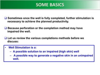
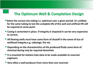
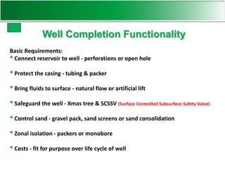
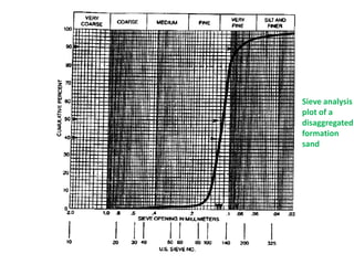
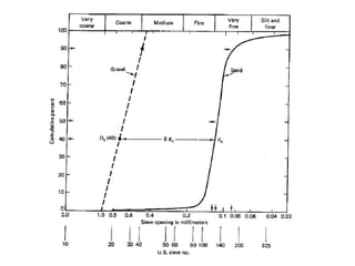
SAND CONTROL
Production Operations
SOME BASICS
 Sometimes once the well is fully completed, further stimulation is
necessary to achieve the planned productivity.
 Because perforation or the completion method may have
impaired the well.
 Let us review the various completions methods before we
discuss:
• Well Stimulation is a:
– A possible solution to an impaired (high skin) well
– A possible way to generate a negative skin in an unimpaired
well.
•Select the correct size tubing i.e. optimum over a given period. It’s unlikely
for the same tubing to last the complete life of the well and artificial lift will
be required at some point.
•Casing is cemented in place. If integrity is impaired it can be very expensive
to correct.
•All flowing wells must have some form of shutoff in the event of loss of
wellhead integrity e.g. sabotage, fire etc.
•Depending on the characteristics of the produced fluids some form of
chemical dosing may be required downhole
•It is essential for bottom hole data to be made available to reservoir
engineers
•Very often a well produces from more than one reservoir
The Optimum Well & Completion Design
Well Completion Functionality
Basic Requirements:
•Connect reservoir to well - perforations or open hole
•Protect the casing - tubing & packer
•Bring fluids to surface - natural flow or artificial lift
•Safeguard the well - Xmas tree & SCSSV (Surface Controlled Subsurface Safety Valve)
•Control sand - gravel pack, sand screens or sand consolidation
•Zonal isolation - packers or monobore
•Costs - fit for purpose over life cycle of well
Above all, produce safely............
• A monobore completion is a
completion with fullbore
access across the payzone,
without diameter restrictions.
• This makes entering the well
with wireline or coiled tubing
much simpler, lowering risk of
problems and so reducing life
cycle cost.
Casing
Tubing
Packer
Liner hanger
Liner
Perforations
Monobore Completion
Allows production
independently from
two zones
Dual Completions
A Petroleum Technologist should ask the Question:
Do we expect any sand from the well?
If so how much and when?
What are we going to do to stop it?
 Sand production occurs when the overburden stresses
round perforations or the wellbore exceed the sand strength.
 The overburden stress increases with drawdown as the
reservoir pressure helping to support the rock
decreases.
Sand Control
Sand Production
Sand production leads to numerous problems
– erosion of downhole tubulars
– erosion of valves, fittings and flowlines
– clogging of surface process equipment
– the well-bore filling-up with sand
– collapsed casing as a result of lack of formation support.
– disposal problems particularly in offshore fields
So:Sand Prediction, andControl is a keyrequirement in many
fields:
Predicting Sand Production
• “FIST” is the Shell in-house sand prediction tool and uses core
strength data, and log strength data (sonic logs, porosity logs)
to predict a failure envelope.
• The envelope indicates at what conditions of a drawdown and
reservoir pressure sand failure may occur and under what
conditions sand production may become excessive.
PT (petroleum technologist) uses a programme called FIST (Fully Integrated
Sand prediction Tool). The input consists of core and log measurements of
rock properties.
Sand Control Techniques
Passive approaches
Maintenance and workover
Rate exclusion
Selective completion practices
Active approaches
Chemical consolidation
High energy resin placement
Consolidated gravel
Slotted liners or screens
Gravel packing
Frac & Pack
Barefoot
Perforated
Cased Hole
Completion Types with no Sand Control
Sand Control Screens
• Slotted liner or screen provides
a down hole filter
• Sand “bridges” on holes in the
screens while production flows
through.
• Sand production is often not
prevented by screens and
failure/erosion can still be a
problem
Bridging
With Well
Sorted Material
Plugging a problem
With Poorly
Sorted Material
Screens work like filters and are designed in such a way
that the slot opening is twice the median grain diameter, so
that particles bridge over the opening.
In this way, the particles don’t plug the slot, but leave
sufficient porosity open between the particles to allow flow
into the screen.
It may mean that some sand is produced until the
bridging is established.
However, if the particles are poorly sorted, then the pore
spaces may be plugged off by smaller particles leading to
lower productivity.
When screens are used in horizontal wells, the annulus is
open, which makes it difficult to do any remedial work on
the formation like pumping acid to stimulate production or
dissolve filter cake.
However, running screens in open hole is cheaper than
running casing, cementing it in place & then perforating.
Wire Wrapped Screen Prepacked Screen Excluder Screen
Screen Types
Expandable Screen/Slotted Tubular
A pipe has overlapping slots cut into it and is expanded by pulling or pushing a cone
through the screen. It easily opens up forming a tight fit with the casing or hole. A much
finer slotted tubular is sandwiched between 2 normal slotted tubulars in order to have a
small slot width for sand control.
• Historically, the most
widely applied sand
control technique
• Uses high permeability
gravel in conjunction with
slotted liner or screen
• Specially sized gravel is
packed into perforations
and annulus to stabilize
formation
Cased Hole
Gravel Pack
Open Hole
Gravel Pack
Gravel Packing
Gravel packing is basically a downhole filter to stop sand
production.
It should work better than just a downhole screen, because
gravel pack sand (rounded sand particles in range of 200 - 1200
microns in diameter) is pumped into the annulus between the
screen and the formation (see next slide for a close-up).
The gravel pack sand is squeezed against the formation sand
to stop it moving and ensures good sand control, with reduced
risk of plugging.
Gravel Packing
Formation
Perforations
Cement
Gravel
Casing
Wire
Wrapped
Screen
Internal Gravel Pack
The gravel pack sand is made of rounded sand particles in range of 200 - 1200
microns in diameter). The sand grains should be well rounded and similar in
size, with <1% fine particles, so that there is maximum permeability through
the gravel pack.
Normally a wire-wrapped screen is used as this has a larger inflow surface
area. The gravel is transported using a carrier fluid which can be brine or a
viscosified (HEC) brine solution. The mixture is called a slurry.
Ideally, you need high viscosity & good carrying capacity in low shear regimes
(in the tubing) and low viscosity when the fluid is being injected into the
formation (low viscosity gives better injectivity).
• Goal is to inject plastic resins into the formation to
provide increased compressive strength while
maintaining acceptable permeability
• Treatment objective are:
– Cover entire perforated interval
– Coat all sand grains
– Concentrate resin at contact points
– Leave pore spaces open
• Three types of resins systems available:
– Epoxies
– Furans (and furan/phenolic blends)
– Phenolics
2nd method: Sand Consolidation
Prepacked
Screen
Chemical
Sand
Consolidation
External
Gravel
Pack
Internal
Gravel
Pack
Frac
and
Pack
Completion Types with Sand Control
• A sieve analysis is a laboratory routine performed on a formation sand
sample for the selection of the proper-sized gravel-pack sand.
• A sieve analysis consists of placing a formation sample at the top of a
series of screens that have progressively smaller mesh sizes downwards in
the sieve stack.
• After placing the sieve stack in a vibrating machine, the sand grains in the
sample will fall through the screens until encountering a screen through
which certain grain sizes cannot pass because the openings in the screen
are too small.
• By weighing the screens before and after sieving, the weight of formation
sample, retained by each size screen, can be determined.
• The cumulative weight percent of each sample retained can be plotted as a
comparison of screen mesh size on semi-log coordinates to obtain a sand
size-distribution plot
Sieve analysis for gravel pack selection
Schwartz sorting criteria
Uc < 3  uniform (well sorted) sand
3 < Uc ≤ 5  medium sand
Uc > 5  non uniform (poorly sorted) sand
Sorting Criteria:-
1. For formation sand having Uc < 5 & ev of sand < 0.05 ft/sec we select df(10) size
2. For formation sand having Uc < 5 & ev of sand > 0.05 ft/sec we select df(40) size
3. For formation sand having Uc > 10 & ev of sand > 0.1 ft/sec we select df(70) size
Diameter of gravel must be 6 times the diameter of the formation sand particles.
And for finding d90 size take Uc as 1.5
• Once the sieve analysis has been performed and plotted, the remainder of the
gravel-pack sizing can be performed graphically.
• With a straight edge, construct the gravel curve so that its uniformity coefficient,
Uc, is 1.5.
• The actual gravel size can be determined by the intercept of gravel curve with the
0 and 100 percentile values. Select to the nearest standard gravel size.
Sieve analysis
plot of a
disaggregated
formation
sand
Given the formation sand sieve analysis as shown in figure (in previous slide).
Determine median sand size & uniformity coefficient of sand: -
Also Select the proper gravel size (i.e. gravel diameter) for a well that is
expected to produce at a rate such that fluid velocity through half of open
screen area is about 0.02 m/sec: -
Use Schwartz gravel pack selection criteria and also mention the criteria.
SAND SORTING CRITERIA
The assortment of chemicals pumped down the well
during drilling and completion can often cause damage to
the surrounding formation by entering the reservoir rock
and blocking the pore throats (the channels in the rock
throughout which the reservoir fluids flow).
Similarly, the act of perforating can have a similar effect by
jetting debris into the perforation channels.
Both these situations reduce the permeability in the near
well bore area and so reduce the flow of fluids into the
well bore.
Let us remember …….
Sand control

Sand control

  • 1.
  • 2.
    SOME BASICS  Sometimesonce the well is fully completed, further stimulation is necessary to achieve the planned productivity.  Because perforation or the completion method may have impaired the well.  Let us review the various completions methods before we discuss: • Well Stimulation is a: – A possible solution to an impaired (high skin) well – A possible way to generate a negative skin in an unimpaired well.
  • 3.
    •Select the correctsize tubing i.e. optimum over a given period. It’s unlikely for the same tubing to last the complete life of the well and artificial lift will be required at some point. •Casing is cemented in place. If integrity is impaired it can be very expensive to correct. •All flowing wells must have some form of shutoff in the event of loss of wellhead integrity e.g. sabotage, fire etc. •Depending on the characteristics of the produced fluids some form of chemical dosing may be required downhole •It is essential for bottom hole data to be made available to reservoir engineers •Very often a well produces from more than one reservoir The Optimum Well & Completion Design
  • 4.
    Well Completion Functionality BasicRequirements: •Connect reservoir to well - perforations or open hole •Protect the casing - tubing & packer •Bring fluids to surface - natural flow or artificial lift •Safeguard the well - Xmas tree & SCSSV (Surface Controlled Subsurface Safety Valve) •Control sand - gravel pack, sand screens or sand consolidation •Zonal isolation - packers or monobore •Costs - fit for purpose over life cycle of well
  • 5.
    Above all, producesafely............
  • 6.
    • A monoborecompletion is a completion with fullbore access across the payzone, without diameter restrictions. • This makes entering the well with wireline or coiled tubing much simpler, lowering risk of problems and so reducing life cycle cost. Casing Tubing Packer Liner hanger Liner Perforations Monobore Completion
  • 7.
  • 8.
    A Petroleum Technologistshould ask the Question: Do we expect any sand from the well? If so how much and when? What are we going to do to stop it?  Sand production occurs when the overburden stresses round perforations or the wellbore exceed the sand strength.  The overburden stress increases with drawdown as the reservoir pressure helping to support the rock decreases. Sand Control
  • 9.
    Sand Production Sand productionleads to numerous problems – erosion of downhole tubulars – erosion of valves, fittings and flowlines – clogging of surface process equipment – the well-bore filling-up with sand – collapsed casing as a result of lack of formation support. – disposal problems particularly in offshore fields So:Sand Prediction, andControl is a keyrequirement in many fields:
  • 10.
    Predicting Sand Production •“FIST” is the Shell in-house sand prediction tool and uses core strength data, and log strength data (sonic logs, porosity logs) to predict a failure envelope. • The envelope indicates at what conditions of a drawdown and reservoir pressure sand failure may occur and under what conditions sand production may become excessive. PT (petroleum technologist) uses a programme called FIST (Fully Integrated Sand prediction Tool). The input consists of core and log measurements of rock properties.
  • 11.
    Sand Control Techniques Passiveapproaches Maintenance and workover Rate exclusion Selective completion practices Active approaches Chemical consolidation High energy resin placement Consolidated gravel Slotted liners or screens Gravel packing Frac & Pack
  • 12.
  • 13.
    Sand Control Screens •Slotted liner or screen provides a down hole filter • Sand “bridges” on holes in the screens while production flows through. • Sand production is often not prevented by screens and failure/erosion can still be a problem Bridging With Well Sorted Material Plugging a problem With Poorly Sorted Material
  • 14.
    Screens work likefilters and are designed in such a way that the slot opening is twice the median grain diameter, so that particles bridge over the opening. In this way, the particles don’t plug the slot, but leave sufficient porosity open between the particles to allow flow into the screen. It may mean that some sand is produced until the bridging is established.
  • 15.
    However, if theparticles are poorly sorted, then the pore spaces may be plugged off by smaller particles leading to lower productivity. When screens are used in horizontal wells, the annulus is open, which makes it difficult to do any remedial work on the formation like pumping acid to stimulate production or dissolve filter cake. However, running screens in open hole is cheaper than running casing, cementing it in place & then perforating.
  • 16.
    Wire Wrapped ScreenPrepacked Screen Excluder Screen Screen Types
  • 17.
    Expandable Screen/Slotted Tubular Apipe has overlapping slots cut into it and is expanded by pulling or pushing a cone through the screen. It easily opens up forming a tight fit with the casing or hole. A much finer slotted tubular is sandwiched between 2 normal slotted tubulars in order to have a small slot width for sand control.
  • 18.
    • Historically, themost widely applied sand control technique • Uses high permeability gravel in conjunction with slotted liner or screen • Specially sized gravel is packed into perforations and annulus to stabilize formation Cased Hole Gravel Pack Open Hole Gravel Pack Gravel Packing
  • 19.
    Gravel packing isbasically a downhole filter to stop sand production. It should work better than just a downhole screen, because gravel pack sand (rounded sand particles in range of 200 - 1200 microns in diameter) is pumped into the annulus between the screen and the formation (see next slide for a close-up). The gravel pack sand is squeezed against the formation sand to stop it moving and ensures good sand control, with reduced risk of plugging. Gravel Packing
  • 20.
  • 21.
    Internal Gravel Pack Thegravel pack sand is made of rounded sand particles in range of 200 - 1200 microns in diameter). The sand grains should be well rounded and similar in size, with <1% fine particles, so that there is maximum permeability through the gravel pack. Normally a wire-wrapped screen is used as this has a larger inflow surface area. The gravel is transported using a carrier fluid which can be brine or a viscosified (HEC) brine solution. The mixture is called a slurry. Ideally, you need high viscosity & good carrying capacity in low shear regimes (in the tubing) and low viscosity when the fluid is being injected into the formation (low viscosity gives better injectivity).
  • 22.
    • Goal isto inject plastic resins into the formation to provide increased compressive strength while maintaining acceptable permeability • Treatment objective are: – Cover entire perforated interval – Coat all sand grains – Concentrate resin at contact points – Leave pore spaces open • Three types of resins systems available: – Epoxies – Furans (and furan/phenolic blends) – Phenolics 2nd method: Sand Consolidation
  • 23.
  • 24.
    • A sieveanalysis is a laboratory routine performed on a formation sand sample for the selection of the proper-sized gravel-pack sand. • A sieve analysis consists of placing a formation sample at the top of a series of screens that have progressively smaller mesh sizes downwards in the sieve stack. • After placing the sieve stack in a vibrating machine, the sand grains in the sample will fall through the screens until encountering a screen through which certain grain sizes cannot pass because the openings in the screen are too small. • By weighing the screens before and after sieving, the weight of formation sample, retained by each size screen, can be determined. • The cumulative weight percent of each sample retained can be plotted as a comparison of screen mesh size on semi-log coordinates to obtain a sand size-distribution plot Sieve analysis for gravel pack selection
  • 25.
    Schwartz sorting criteria Uc< 3  uniform (well sorted) sand 3 < Uc ≤ 5  medium sand Uc > 5  non uniform (poorly sorted) sand Sorting Criteria:- 1. For formation sand having Uc < 5 & ev of sand < 0.05 ft/sec we select df(10) size 2. For formation sand having Uc < 5 & ev of sand > 0.05 ft/sec we select df(40) size 3. For formation sand having Uc > 10 & ev of sand > 0.1 ft/sec we select df(70) size Diameter of gravel must be 6 times the diameter of the formation sand particles. And for finding d90 size take Uc as 1.5
  • 27.
    • Once thesieve analysis has been performed and plotted, the remainder of the gravel-pack sizing can be performed graphically. • With a straight edge, construct the gravel curve so that its uniformity coefficient, Uc, is 1.5. • The actual gravel size can be determined by the intercept of gravel curve with the 0 and 100 percentile values. Select to the nearest standard gravel size.
  • 28.
    Sieve analysis plot ofa disaggregated formation sand
  • 29.
    Given the formationsand sieve analysis as shown in figure (in previous slide). Determine median sand size & uniformity coefficient of sand: - Also Select the proper gravel size (i.e. gravel diameter) for a well that is expected to produce at a rate such that fluid velocity through half of open screen area is about 0.02 m/sec: - Use Schwartz gravel pack selection criteria and also mention the criteria. SAND SORTING CRITERIA
  • 32.
    The assortment ofchemicals pumped down the well during drilling and completion can often cause damage to the surrounding formation by entering the reservoir rock and blocking the pore throats (the channels in the rock throughout which the reservoir fluids flow). Similarly, the act of perforating can have a similar effect by jetting debris into the perforation channels. Both these situations reduce the permeability in the near well bore area and so reduce the flow of fluids into the well bore. Let us remember …….