Downloaded 342 times


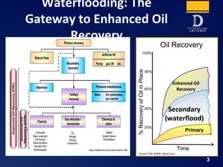
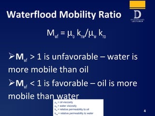

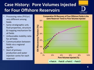


This document outlines best practices for waterflood design and operation in enhanced oil recovery, emphasizing key factors like injection efficiency, water quality, and subsurface integrity. It includes technical discussions on mobility ratios, voidage replacement ratios, and the importance of surveillance and interdisciplinary teamwork. It also highlights emerging technologies and provides key takeaways for effective waterflood management.