SlideShare a Scribd company logo
1 of 10
Download to read offline
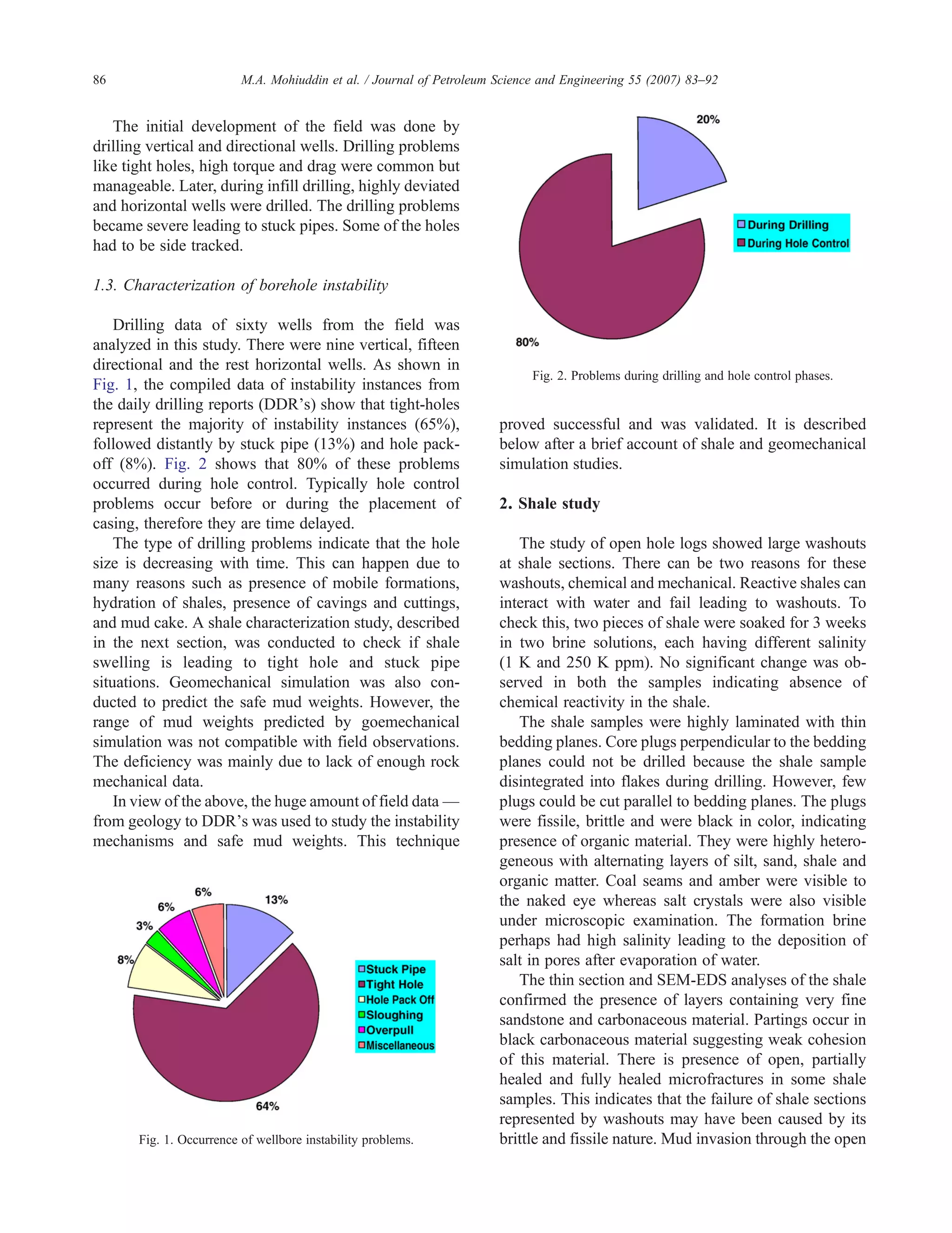
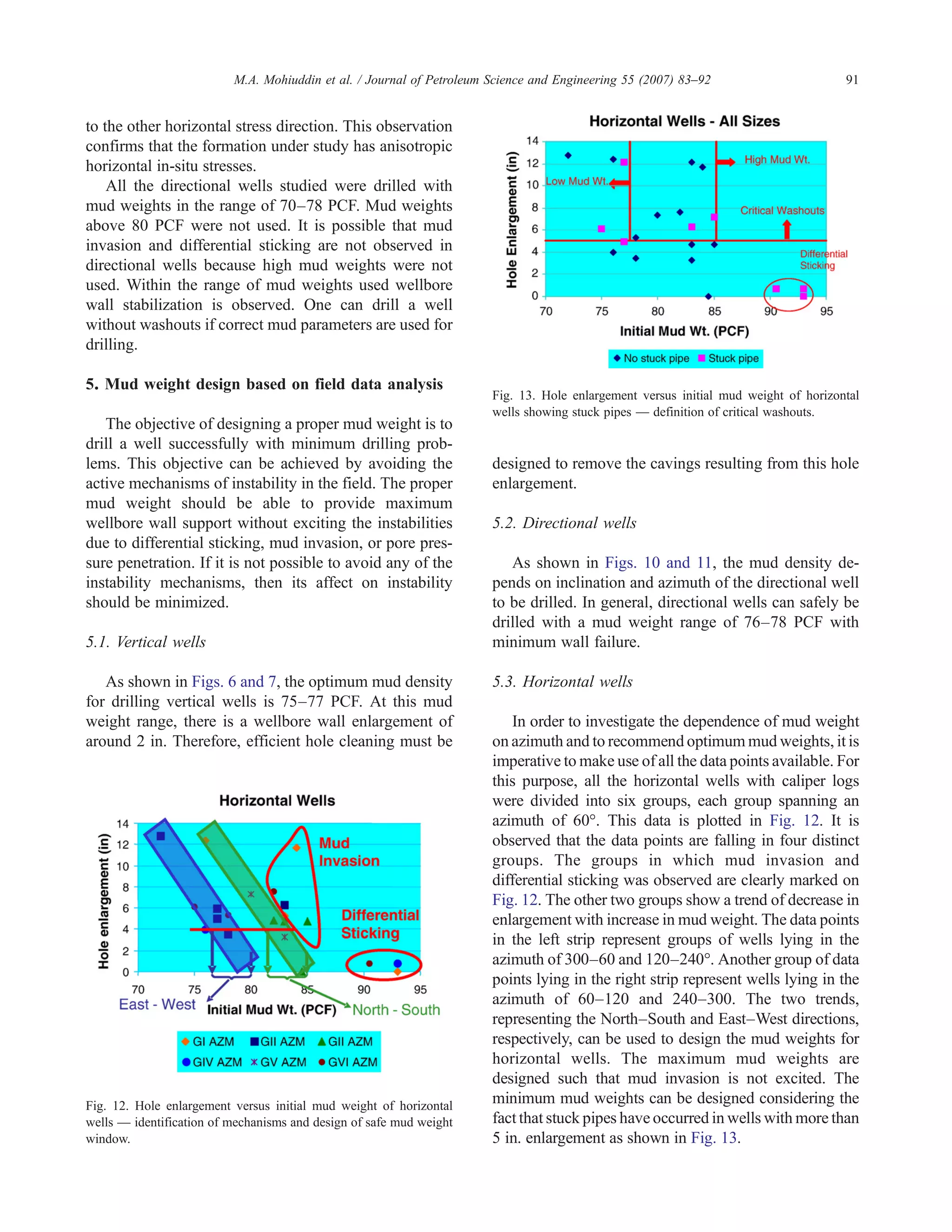
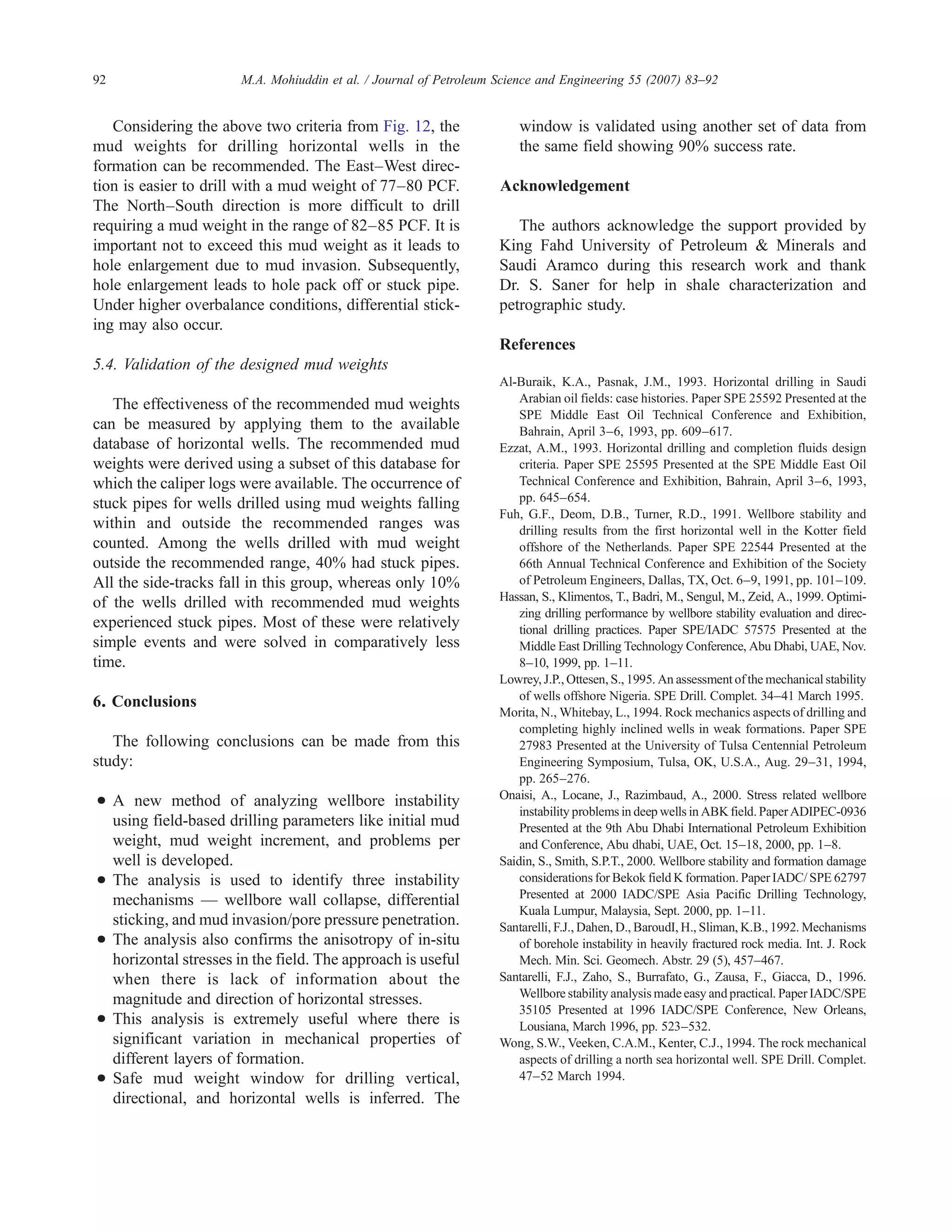
Analysis of wellbore instability in vertical, directional,
and horizontal wells using field data
M.A. Mohiuddin, K. Khan, A. Abdulraheem ⁎, A. Al-Majed, M.R. Awal
Center for Petroleum and Minerals, Research Institute, King Fahd University of Petroleum and Minerals,
P.O. Box # 755, Dhahran - 31261, Saudi Arabia
Received 18 April 2005; accepted 26 April 2006
Abstract
An old offshore field produced using vertical and directional wells is being redeveloped by drilling horizontal wells. The
experience gained while drilling vertical and directional wells is not useful for drilling horizontal wells, as the failure rate is 1 in 3
holes. Quantification of drilling problems in sixty wells show that majority are tight holes. Stuck pipes and hole pack offs are also
significant in number. The major loss of productivity is due to stuck pipes. A preliminary study of shale in sections where problems
occur, show no chemical reactivity. Petrographic analysis confirmed the fissile and brittle nature of shale with presence of open,
partially healed microfractures and partings. Rock mechanical simulation predicted the safe mud weight window for horizontal
wells as 76–90 PCF, depending on azimuth. However, all the horizontal wells analyzed in this study were drilled using the same
mud weight window. Therefore, field based parameters like initial mud weight used for drilling, mud weight increment and
problems per well were used to analyze wellbore instability, identify different instability mechanisms and design safe mud weight
window for drilling horizontal wells. These parameters were used first on the drilling data of vertical wells to develop the procedure
for the analysis of wellbore instability and identify the mechanisms of instability. The developed procedure was then applied to the
drilling data of directional wells to show the dependence of mud weight on the inclination and azimuth of the well. Finally, the
procedure was applied to horizontal wells data along with the concept of critical washouts to infer the safe mud weight window as
77–80 PCF in East–West and 82–85 PCF in North–South directions. The safe mud weight window is validated on another set of
drilling data showing 90% success rate. The analysis confirms the existence of anisotropy in horizontal stresses and is extremely
useful in cases where there is significant variation in mechanical properties of different layers of reservoir rock.
© 2006 Elsevier B.V. All rights reserved.
Keywords: Wellbore instability; Drilling data analysis; Wellbore wall stabilization; Differential sticking; Mud invasion; Pore pressure penetration
1. Introduction
Wellbore instability manifests itself in different ways
like hole pack off, excessive reaming, overpull, torque
and drag, sometimes leading to stuck pipe that may
require plugging and side tracking. This requires
additional time to drill a hole, driving up the cost of
reservoir development significantly. In case of offshore
fields, loss of hole is more critical due to a limited
number of holes that can be drilled from a platform.
Drilling an ingauge hole is an interplay of two
factors: uncontrollable and controllable. Uncontrollable
Journal of Petroleum Science and Engineering 55 (2007) 83–92
www.elsevier.com/locate/petrol
⁎ Corresponding author.
E-mail addresses: mamuddin@kfupm.edu.sa (M.A. Mohiuddin),
aazeez@kfupm.edu.sa (A. Abdulraheem).
0920-4105/$ - see front matter © 2006 Elsevier B.V. All rights reserved.
doi:10.1016/j.petrol.2006.04.021
factors are the earth stresses (horizontal and vertical),
pore pressure, rock strength and rock chemistry.
Controllable factors include mud weight, wellbore
azimuth and inclination. A proper drilling program
optimizes the controllable factors with the knowledge of
uncontrollable factors. The controllable factors are
heavily dependent on rock mechanical behavior of
rock. For example, it is well known in the rock
mechanics literature that the change in mud weight
with the angle of inclination depends on the in-situ
stresses, if the rock anisotropy is negligible. If a normal
stress regime is present, then the horizontal wells are
more susceptible to instabilities and hence the most
difficult to drill. The mud weight control plays a crucial
role in instability management with the angle of
inclination. Unfortunately, drillers traditionally depend
on empirically derived “Rules of Thumb” rather than
rock mechanic principles of rock stability and failure in
designing mud weight.
1.1. Literature review
Design of wells using principles of rock mechanics is
well reported in the literature (Wong et al., 1994; Morita
and Whitebay, 1994). A case study of designing a
horizontal well in Vlieland sand in the Dutch sector of
North Sea is reported by Fuh et al. (1991). The rock
mechanical parameters such as in-situ stresses, strength
and pore pressure of the Vlieland sand and shale which
overlies it were computed from the back analysis of
drilling problems from previous eight vertical wells
drilled in the area. A mud program was designed using
these estimated parameters and a horizontal hole was
drilled with few manageable instances of instability.
Drilling of overburden shales in offshore Nigeria
resulted in several problems of stuck pipes and
sidetracks. A detailed rock mechanics study was
conducted to characterize the state of in-situ stress,
rock strength, and formation pore pressure. These
parameters were used to perform a geomechanical
simulation and estimate safe mud weights. Use of these
mud weights led to a marked improvement in wellbore
stability (Lowrey and Ottesen, 1995).
Four wells drilled in Gulf of Suez and Mediterranean
Sea, offshore Egypt, were analyzed for wellbore
instability, to improve drilling performance in future
wells (Hassan et al., 1999). A suite of logs, including
DSI sonic, GR, and density were used as input to
IMPACT-ELAN of Geoframe to predict rock strength,
petrophysical properties, and safe mud weight windows.
The weak shales in the overburden were failing due to
inadequate wall support inspite of using oil based mud
(OBM). The simulation predicted higher mud weight for
adequate wall support. Use of predicted higher mud
weights during drilling improved the hole condition and
related instabilities. Therefore, OBM used of to drill
shaly sections should be checked for correct mud
weight.
Saidin and Smith (2000) discussed wellbore insta-
bility encountered when drilling through the Terengganu
shale (K-shale), Bekok field, Malaysia. Due to the time
dependency of the observed instability cases, K-shale
was thought of as reactive and unstable due to shale–
fluid interaction. Invert emulsion OBM was used to drill
the wells. This, however, resulted in severe formation
damage without any improvement in stability. Rock
characterization and laboratory measurements of rock-
mechanical properties indicated that K-shales had predo-
minantly non-reactive weak clay. This information
helped in improving the design of mud weight window
leading to successful completion of a new well. To mi-
nimize differential sticking due to high mud weights,
invert emulsion SBM was used.
In many cases, factors like magnitude of the
maximum horizontal in-situ stress and variations in
rock strength are not well known. These parameters are
estimated using empirical or semi-empirical approaches.
Under such circumstances, the safe mud weight window
predicted using geomechanical simulation is often not
realistic. For such cases, drilling data accumulated from
previous problematic wells can be used to predict safe
mud weight window. A brief review of studies using the
above mentioned approach is given in the following
paragraphs.
Santarelli et al. (1996) presented wellbore instability
problems occurring in a developed field in Italy. The
problems were back analyzed with respect to the mud
types, mud weights, azimuths, and stress regime. More
drilling problems like reaming and stuck pipe occurred
in a particular azimuth. This proved the existence of
anisotropic distribution of horizontal stresses, which
was not known because of absence of any in-situ stress
related data. The non-inhibitive water based mud gave
better results compared to other mud system. In the light
of new data, drilling practices which were planned
during appraisal drilling phase were continued with
necessary modifications.
Santarelli et al. (1992) presented a case study of
drilling in highly fractured volcanic rocks at great
depths. Use of OBM did not solve the problem since the
instability was not due to clay. Analysis of the clay in
those rocks showed that they were non-reactive. It was
found that the main mechanism of instability was mud
penetration in fractures which led to eventual erosion of
84 M.A. Mohiuddin et al. / Journal of Petroleum Science and Engineering 55 (2007) 83–92
the wellbore wall due to inadequate wall support.
Appropriate mud weight was designed by simulating the
fractured rock mass using discrete element modeling.
Use of the new mud weight, lower than that being used,
along with proper fracture plugging material in WBM
proved successful. Classical method of solving the
instability by increasing mud weight could have
aggravated the problem.
In general, wellbore instability is caused by a
combination of different reasons or presence of more
than one mechanisms of instability. Wells drilled in
complex geological areas encounter many layers of rock
having different properties. Some layers could be weak,
while others brittle, fractured, chemically reactive or
rubble. There is no simple solution for wellbore
instability in such cases. A collapsing weak layer
needs high mud weight for stability, but increasing the
mud weight could excite instability in fractured layers
by mud invasion. Therefore, such cases require careful
rock characterization and mud weight optimization.
In the past, fields were developed using vertical wells
which did not exhibit any drilling trouble. The trend
nowadays is to drill horizontal wells to enhance
productivity. The experience of drilling vertical wells
is carried forward without appropriate modifications to
drill the horizontal wells resulting in wellbore
instabilities.
Severe instability was encountered while drilling
horizontal drains in Hamlah-Gulailah Formation, ABK
field, offshore Abu Dhabi, though vertical wells were
drilled without encountering any significant problem.
To analyze the instability problem, a comprehensive
rock mechanical study was carried out to characterize
rock strength and in-situ horizontal stresses. The study
suggested that the horizontal stresses were anisotropic in
nature with strike–slip–thrust stress regime. The rocks
were weak and fissured. The rock mechanical simula-
tion predicted higher mud weights than those actually
used in the field (Onaisi et al., 2000).
Al-Buraik and Pasnak (1993) discussed well plans,
drilling fluids, casing and cementing liners, coring,
logging, completions, and drilling problems encoun-
tered in more than a dozen horizontal wells drilled both
in sandstone and carbonate reservoirs in Saudi Arabia.
The wellbore, in sandstone reservoirs, passed through
shale and shale–sand stringers before reaching TD
(target depth). Because of the consolidated nature of the
sand, these wells are completed with 7ʺ LNRs (liners).
Three wells suffered from major wellbore instability
problems such as borehole collapse leading to stuck
pipe. The collapse due to the mechanical instability of
shale was aggravated due to extended exposure time.
Some of the shale layers needed a minimum mud weight
of 92 PCF (12.3 PPG) in order to keep the borehole
open. Several stuck liners and casings were experienced
in holes drilled with motor. This problem was partially
solved by reaming the motored hole with stiff, non-
drilling reaming assembly before running the liner or
casing.
Ezzat (1993) discussed different laboratory tests
performed for suitable mud design for drilling Khafji
and other reservoirs in Saudi Arabia. The petrophysical
examination of Khafji cores revealed that the formation
was basically sandstone with shale stringers, shaly sand,
coal/lignite/amber (plant remains and fossilized tree
resins) and iron rich shale/sand near the top of the
reservoir. The shale was characterized as water-sensitive
with kaolinite up to 49 wt.%, chlorite up to 19 wt.%, and
mixed layer illite/montmorillonite up to 13 wt.%. This
unstable shale caved in, if proper mud weight was not
used during drilling. In some instances mud weights
greater than formation fracture pressure had to be used
to keep the hole open. Use of oil-based mud resulted in
reduction of wellbore instability cases. Among the
reasons that caused mechanical instability were erosion
of unconsolidated sand, gas cut mud and hole fill after
trip, pipe whip and drillstring sticking. Appropriate
actions were taken to solve these problems.
Thus several studies have been conducted to design
safe mud weight window using field drilling data. In this
paper, wellbore instability as a function of shale–mud
interaction, rock mechanical simulation, safe mud
weight prediction, and analysis of drilling data has
been studied. This paper proposes new parameters not
used so far to develop a method of wellbore instability
analysis and calculation of safe mud weight window.
This method of analysis is very useful when in-situ
stress data and rock strength data are not available or
where there is significant variation in rock properties
through different formation layers.
1.2. Reservoir geology and drilling experience
The field under study can be divided into three main
lithological sequences. The upper part has predomi-
nantly shale with coal and sand stringers. The middle
part has clean sand and the lower part has sand and shale
stringers. The target zone for the development wells has
clean sand. The trajectories of these wells in shale–
coal–sand stringers of the upper zone are highly
deviated and long. Since longer deviated trajectories
have to be drilled, it takes more time to drill, giving rise
to delayed problems like tight hole, hole pack off, and
irremedial stuck pipe which require side tracking.
85M.A. Mohiuddin et al. / Journal of Petroleum Science and Engineering 55 (2007) 83–92
The initial development of the field was done by
drilling vertical and directional wells. Drilling problems
like tight holes, high torque and drag were common but
manageable. Later, during infill drilling, highly deviated
and horizontal wells were drilled. The drilling problems
became severe leading to stuck pipes. Some of the holes
had to be side tracked.
1.3. Characterization of borehole instability
Drilling data of sixty wells from the field was
analyzed in this study. There were nine vertical, fifteen
directional and the rest horizontal wells. As shown in
Fig. 1, the compiled data of instability instances from
the daily drilling reports (DDR's) show that tight-holes
represent the majority of instability instances (65%),
followed distantly by stuck pipe (13%) and hole pack-
off (8%). Fig. 2 shows that 80% of these problems
occurred during hole control. Typically hole control
problems occur before or during the placement of
casing, therefore they are time delayed.
The type of drilling problems indicate that the hole
size is decreasing with time. This can happen due to
many reasons such as presence of mobile formations,
hydration of shales, presence of cavings and cuttings,
and mud cake. A shale characterization study, described
in the next section, was conducted to check if shale
swelling is leading to tight hole and stuck pipe
situations. Geomechanical simulation was also con-
ducted to predict the safe mud weights. However, the
range of mud weights predicted by goemechanical
simulation was not compatible with field observations.
The deficiency was mainly due to lack of enough rock
mechanical data.
In view of the above, the huge amount of field data —
from geology to DDR's was used to study the instability
mechanisms and safe mud weights. This technique
proved successful and was validated. It is described
below after a brief account of shale and geomechanical
simulation studies.
2. Shale study
The study of open hole logs showed large washouts
at shale sections. There can be two reasons for these
washouts, chemical and mechanical. Reactive shales can
interact with water and fail leading to washouts. To
check this, two pieces of shale were soaked for 3 weeks
in two brine solutions, each having different salinity
(1 K and 250 K ppm). No significant change was ob-
served in both the samples indicating absence of
chemical reactivity in the shale.
The shale samples were highly laminated with thin
bedding planes. Core plugs perpendicular to the bedding
planes could not be drilled because the shale sample
disintegrated into flakes during drilling. However, few
plugs could be cut parallel to bedding planes. The plugs
were fissile, brittle and were black in color, indicating
presence of organic material. They were highly hetero-
geneous with alternating layers of silt, sand, shale and
organic matter. Coal seams and amber were visible to
the naked eye whereas salt crystals were also visible
under microscopic examination. The formation brine
perhaps had high salinity leading to the deposition of
salt in pores after evaporation of water.
The thin section and SEM-EDS analyses of the shale
confirmed the presence of layers containing very fine
sandstone and carbonaceous material. Partings occur in
black carbonaceous material suggesting weak cohesion
of this material. There is presence of open, partially
healed and fully healed microfractures in some shale
samples. This indicates that the failure of shale sections
represented by washouts may have been caused by its
brittle and fissile nature. Mud invasion through the openFig. 1. Occurrence of wellbore instability problems.
Fig. 2. Problems during drilling and hole control phases.
86 M.A. Mohiuddin et al. / Journal of Petroleum Science and Engineering 55 (2007) 83–92
microfractures and partings may have led to the loss of
overbalance leading to washouts.
3. Geomechanical simulation
The failure of the shale layers was simulated using a
software called PBore-3D. Any geomechanical simula-
tor needs the strength properties of rocks and in-situ
stress magnitudes as input. The Poisson's ratio and
Young's modulus of the shale layers were calculated
using sonic logs and then calibrated with static core
measurements. The strength parameters like cohesion
and internal friction angle were estimated from empirical
correlations for log data and then calibrated with
available triaxial test results. The in-situ stress regime
is a transition from normal to thrust type with the maxi-
mum horizontal stress slightly higher than the vertical
stress, i.e., σHmax ≥σv Nσhmin. Considering shear failure
in compression and tensile failure as fracture limit, the
safe mud weight window for horizontal wells is pre-
dicted from 76 to 90 PCF depending upon the azimuth of
the well.
4. Development of field data analysis technique
4.1. Analysis of vertical wells
As seen in Fig. 3, a range of initial mud weights form
69 to 82 PCF was used to drill vertical wells. The data is
used to evaluate the performance of mud weight with
respect to the number of problems encountered. As
shown in Fig. 3, there is a very weak correlation bet-
ween initial mud weight used and number of problems
encountered. But if the analysis is limited to the mud
weight range of 70–75 PCF, the numbers of problems
show a monotonous decrease from nine to zero. Only
one point is before 70 PCF is not following the trend.
The analysis indicates that even though there were
washouts in the well, no instability problems were re-
ported perhaps because of efficient cleaning or slow
drilling. Points beyond 75 PCF represent those cases
where other instability mechanisms such as mud in-
vasion were active.
Usually, instability is managed by increasing the mud
weight. As observed in Fig. 4, in the range of 70–75 PCF,
the maximum mud weight increment was applied for
wells drilled with lower initial mud weights. The mud
weight increment decreases monotonously in this range,
confirming the observation that wells drilled with a
starting mud weight of around 75 PCF were the most
stable. The trend usually followed in industry is
confirmed in Fig. 5. As shown in the figure, a strong
correlation is observed between the number of problems
encountered and the mud weight increment to counteract
the instability. The initial mud weight was not high
enough to support the wall resulting in washouts and the
subsequent problems. The mud weight increments have
significantly helped in decreasing these problems, as
evident in the figure.
Fig. 3. Problems per well versus initial mud weight of vertical wells.
Fig. 4. Mud weight increment versus initial mud weight of vertical
wells.
Fig. 5. Mud weight increment versus problems per well of vertical
wells.
87M.A. Mohiuddin et al. / Journal of Petroleum Science and Engineering 55 (2007) 83–92
Fig. 6 shows the hole enlargement of vertical wells
with initial mud weight. It is observed that the hole
enlargement is decreasing with the increase in mud
weight in the range of 70–76 PCF. Interestingly, con-
trary to the normal expected trend, the hole enlargement
increased for the mud weight value beyond 76 PCF.
Fig. 7 shows the relevant caliper logs of selected vertical
wells. The wellbore wall stabilization as indicated by
decreased washout with increase in mud weight is
clearly evident. However, when mud weight is greater
than 76 PCF, increase in hole size (washouts) at certain
locations were observed. This increase in washouts
could possibly be due to the mud invasion at high
overbalance.
Fig. 8 shows the relationship of the number of
problems per well with hole enlargement. For the wells
in the range of 70–76 PCF, the problems per well in-
creased with enlargement. The wells drilled with higher
mud weight do not follow this trend, and show more
problems per well at smaller enlargements. This is
because these wells experienced drilling problems such as
overpull and stuckpipe due to high overbalance. The origin
of problems for wells drilled in the range of 70–76 PCF
was the increased volume of cuttings and cavings in the
hole. Hence the problems increased with increase in
enlargement. It can readily be inferred from this infor-
mation that the drilling difficulty was due to the extra
amount of cuttings and cavings present in the hole. This
can be controlled by the use of correct mud weight. If mud
weight is high, it gives rise to problems due to differential
sticking and mud invasion or pore pressure penetration.
Hence, optimizing the mud weight to reduce the volume of
cavings as well as avoid differential sticking or mud
invasion is essential. Figs. 6, 7 and 8 also clearly show that
it may not be possible to have a vertical well without
washouts. However, these washouts can be minimized and
the potential drilling problems better managed.
From the analysis of initial mud weight, mud weight
increment, problems per well and hole enlargement of
vertical wells, three instability mechanisms have been
identified. If sufficient mud weight is not used, wellbore
wall support is not available and the wellbore wall
collapses. The instability due to wellbore wall collapse
can be avoided by using appropriate mud weight that
adequately supports the wall. Other instability mechan-
isms are mud invasion and differential sticking at higher
mud weights. Therefore it is essential to drill vertical
wells using an optimum mud weight that avoids the
above instability mechanisms.
4.2. Analysis of directional wells
The mud weight increment and the problems per well
decreased with higher initial mud weights for directional
wells (Fig. 9). In general, the mud weight increment for
this group of wells is less than vertical wells. This could
be an indication of the ease of drilling. Also the change
in mud weights and problems experienced are negligible
when the well is drilled with a mud weight of 75 PCF or
just above it. The range of mud weights used for this
group of wells is smaller than the one used for vertical
wells and falls within the range of interest. Therefore,
we see only one type of behavior showing decrease in
mud weight increment and problems per well with
higher initial mud weight, but the scatter of points is
more here. The possible reasons for this scatter could be
due to a combination of several parameters such as in-
clination angle, azimuth, reservoir heterogeneity or ex-
posure time for different wells, Santarelli et al. (1996).
The following discussion also supports this view.
At this point, it may be pointed out that R2
values for
some of the graphs presented earlier are low. Due to nature
of data coming from a huge field, the scatter is expected to
be there. The objective here is not to develop equations
but to see the trends. Therefore, the safe mudweights
deduced from these graphs are valid for the given ranges
only.
Fig. 10 shows the hole enlargement with initial mud
weights for directional wells. A general trend of dec-
rease in enlargement with increase in mud weight with a
lot of scatter in the data points is observed. In the case of
well D9, there is no washout. For the purpose of
classification, wells having angle of inclination between
5–60° were called directional. In the following, the
possibility of this scatter due to the change in inclination
angle is explored.
It is observed that wells D97, D94 and D9, which have
an inclination angle of 25° follow a trend. Well D61 with
an inclination angle of 4–7° in the formation also followsFig. 6. Hole enlargement versus initial mud weight of vertical wells.
88 M.A. Mohiuddin et al. / Journal of Petroleum Science and Engineering 55 (2007) 83–92
Fig.7.Open-holecaliperlogofselectedverticalwellsshowingwellborewallsupportandpossiblemudinvasion.
89M.A. Mohiuddin et al. / Journal of Petroleum Science and Engineering 55 (2007) 83–92
the same trend. Wells D17, D45, D42, D30 and D79 have
an angle of inclination around 45° in the formation. These
wells can be divided into two groups. For wells D42, D30
and D79 (Group I), the enlargement decreases with
increase in mud weight. The other group of wells (D17,
D45 and D30) has an opposite trend of increase in
enlargement with mud weight. The remaining three wells
namely, D09, D43 and D06 have an angle of inclination of
35° in the formation. This group of wells also does not
follow a trend with mud weight. The enlargement de-
creases and then increases with mud weight. It is possible
that the wells not following the trend of decrease in
enlargement with mud weight lie in different azimuths.
This aspect is also studied in detail as described below.
Fig. 11 shows the hole enlargement of directional
wells drilled in similar azimuthal directions. For wells
drilled North–South, the enlargement decreases with
increase in mud weight. The upper line is for wells
having inclination angle of 48° and lower line is for
wells having 25° inclination angle. Wells drilled in
NNE–SSW direction also follow a general trend of
decrease in enlargement with increase in mud weight.
Well D17, having an inclination of 50°, is an exception.
It has small enlargement at a low mud weight of 70 PCF.
Wells drilled East–West also follow the same trend of
decrease in enlargement with mud weight. From the
above analysis it is clear that the scatter in data in
Figs. 10 and 11 is due to different inclinations and
azimuth.
4.3. Anisotropy in horizontal stresses
If we compare wells drilled in North–South and
East–West direction, we observe that there is more
enlargement for the same mud weight for wells in
North–South direction. It is to be noted that the
North–South direction is closer to the direction of one of
the horizontal stresses and East–West direction is closer
Fig. 8. Problems per well versus hole enlargement of vertical wells.
Fig. 9. Problems per well and mud weight increment versus initial mud
weight of directional wells.
Fig. 10. Hole enlargement versus initial mud weight of directional
wells studied with respect to inclination angle.
Fig. 11. Hole enlargement versus initial mud weight of directional
wells studied with respect to azimuth.
90 M.A. Mohiuddin et al. / Journal of Petroleum Science and Engineering 55 (2007) 83–92
to the other horizontal stress direction. This observation
confirms that the formation under study has anisotropic
horizontal in-situ stresses.
All the directional wells studied were drilled with
mud weights in the range of 70–78 PCF. Mud weights
above 80 PCF were not used. It is possible that mud
invasion and differential sticking are not observed in
directional wells because high mud weights were not
used. Within the range of mud weights used wellbore
wall stabilization is observed. One can drill a well
without washouts if correct mud parameters are used for
drilling.
5. Mud weight design based on field data analysis
The objective of designing a proper mud weight is to
drill a well successfully with minimum drilling prob-
lems. This objective can be achieved by avoiding the
active mechanisms of instability in the field. The proper
mud weight should be able to provide maximum
wellbore wall support without exciting the instabilities
due to differential sticking, mud invasion, or pore pres-
sure penetration. If it is not possible to avoid any of the
instability mechanisms, then its affect on instability
should be minimized.
5.1. Vertical wells
As shown in Figs. 6 and 7, the optimum mud density
for drilling vertical wells is 75–77 PCF. At this mud
weight range, there is a wellbore wall enlargement of
around 2 in. Therefore, efficient hole cleaning must be
designed to remove the cavings resulting from this hole
enlargement.
5.2. Directional wells
As shown in Figs. 10 and 11, the mud density de-
pends on inclination and azimuth of the directional well
to be drilled. In general, directional wells can safely be
drilled with a mud weight range of 76–78 PCF with
minimum wall failure.
5.3. Horizontal wells
In order to investigate the dependence of mud weight
on azimuth and to recommend optimum mud weights, it is
imperative to make use of all the data points available. For
this purpose, all the horizontal wells with caliper logs
were divided into six groups, each group spanning an
azimuth of 60°. This data is plotted in Fig. 12. It is
observed that the data points are falling in four distinct
groups. The groups in which mud invasion and
differential sticking was observed are clearly marked on
Fig. 12. The other two groups show a trend of decrease in
enlargement with increase in mud weight. The data points
in the left strip represent groups of wells lying in the
azimuth of 300–60 and 120–240°. Another group of data
points lying in the right strip represent wells lying in the
azimuth of 60–120 and 240–300. The two trends,
representing the North–South and East–West directions,
respectively, can be used to design the mud weights for
horizontal wells. The maximum mud weights are
designed such that mud invasion is not excited. The
minimum mud weights can be designed considering the
fact that stuck pipes have occurred in wells with more than
5 in. enlargement as shown in Fig. 13.
Fig. 12. Hole enlargement versus initial mud weight of horizontal
wells — identification of mechanisms and design of safe mud weight
window.
Fig. 13. Hole enlargement versus initial mud weight of horizontal
wells showing stuck pipes — definition of critical washouts.
91M.A. Mohiuddin et al. / Journal of Petroleum Science and Engineering 55 (2007) 83–92
Considering the above two criteria from Fig. 12, the
mud weights for drilling horizontal wells in the
formation can be recommended. The East–West direc-
tion is easier to drill with a mud weight of 77–80 PCF.
The North–South direction is more difficult to drill
requiring a mud weight in the range of 82–85 PCF. It is
important not to exceed this mud weight as it leads to
hole enlargement due to mud invasion. Subsequently,
hole enlargement leads to hole pack off or stuck pipe.
Under higher overbalance conditions, differential stick-
ing may also occur.
5.4. Validation of the designed mud weights
The effectiveness of the recommended mud weights
can be measured by applying them to the available
database of horizontal wells. The recommended mud
weights were derived using a subset of this database for
which the caliper logs were available. The occurrence of
stuck pipes for wells drilled using mud weights falling
within and outside the recommended ranges was
counted. Among the wells drilled with mud weight
outside the recommended range, 40% had stuck pipes.
All the side-tracks fall in this group, whereas only 10%
of the wells drilled with recommended mud weights
experienced stuck pipes. Most of these were relatively
simple events and were solved in comparatively less
time.
6. Conclusions
The following conclusions can be made from this
study:
• A new method of analyzing wellbore instability
using field-based drilling parameters like initial mud
weight, mud weight increment, and problems per
well is developed.
• The analysis is used to identify three instability
mechanisms — wellbore wall collapse, differential
sticking, and mud invasion/pore pressure penetration.
• The analysis also confirms the anisotropy of in-situ
horizontal stresses in the field. The approach is useful
when there is lack of information about the
magnitude and direction of horizontal stresses.
• This analysis is extremely useful where there is
significant variation in mechanical properties of
different layers of formation.
• Safe mud weight window for drilling vertical,
directional, and horizontal wells is inferred. The
window is validated using another set of data from
the same field showing 90% success rate.
Acknowledgement
The authors acknowledge the support provided by
King Fahd University of Petroleum & Minerals and
Saudi Aramco during this research work and thank
Dr. S. Saner for help in shale characterization and
petrographic study.
References
Al-Buraik, K.A., Pasnak, J.M., 1993. Horizontal drilling in Saudi
Arabian oil fields: case histories. Paper SPE 25592 Presented at the
SPE Middle East Oil Technical Conference and Exhibition,
Bahrain, April 3–6, 1993, pp. 609–617.
Ezzat, A.M., 1993. Horizontal drilling and completion fluids design
criteria. Paper SPE 25595 Presented at the SPE Middle East Oil
Technical Conference and Exhibition, Bahrain, April 3–6, 1993,
pp. 645–654.
Fuh, G.F., Deom, D.B., Turner, R.D., 1991. Wellbore stability and
drilling results from the first horizontal well in the Kotter field
offshore of the Netherlands. Paper SPE 22544 Presented at the
66th Annual Technical Conference and Exhibition of the Society
of Petroleum Engineers, Dallas, TX, Oct. 6–9, 1991, pp. 101–109.
Hassan, S., Klimentos, T., Badri, M., Sengul, M., Zeid, A., 1999. Optimi-
zing drilling performance by wellbore stability evaluation and direc-
tional drilling practices. Paper SPE/IADC 57575 Presented at the
Middle East Drilling Technology Conference, Abu Dhabi, UAE, Nov.
8–10, 1999, pp. 1–11.
Lowrey, J.P., Ottesen, S., 1995. An assessment of the mechanical stability
of wells offshore Nigeria. SPE Drill. Complet. 34–41 March 1995.
Morita, N., Whitebay, L., 1994. Rock mechanics aspects of drilling and
completing highly inclined wells in weak formations. Paper SPE
27983 Presented at the University of Tulsa Centennial Petroleum
Engineering Symposium, Tulsa, OK, U.S.A., Aug. 29–31, 1994,
pp. 265–276.
Onaisi, A., Locane, J., Razimbaud, A., 2000. Stress related wellbore
instability problems in deep wells in ABK field.Paper ADIPEC-0936
Presented at the 9th Abu Dhabi International Petroleum Exhibition
and Conference, Abu dhabi, UAE, Oct. 15–18, 2000, pp. 1–8.
Saidin, S., Smith, S.P.T., 2000. Wellbore stability and formation damage
considerations for Bekok field K formation. Paper IADC/ SPE 62797
Presented at 2000 IADC/SPE Asia Pacific Drilling Technology,
Kuala Lumpur, Malaysia, Sept. 2000, pp. 1–11.
Santarelli, F.J., Dahen, D., BaroudI, H., Sliman, K.B., 1992. Mechanisms
of borehole instability in heavily fractured rock media. Int. J. Rock
Mech. Min. Sci. Geomech. Abstr. 29 (5), 457–467.
Santarelli, F.J., Zaho, S., Burrafato, G., Zausa, F., Giacca, D., 1996.
Wellbore stability analysis made easy and practical. Paper IADC/SPE
35105 Presented at 1996 IADC/SPE Conference, New Orleans,
Lousiana, March 1996, pp. 523–532.
Wong, S.W., Veeken, C.A.M., Kenter, C.J., 1994. The rock mechanical
aspects of drilling a north sea horizontal well. SPE Drill. Complet.
47–52 March 1994.
92 M.A. Mohiuddin et al. / Journal of Petroleum Science and Engineering 55 (2007) 83–92

More Related Content

What's hot

Performance of square footing resting on laterally confined sand
Performance of square footing resting on laterally confined sandPerformance of square footing resting on laterally confined sand
Performance of square footing resting on laterally confined sandeSAT Publishing House
 
Abhishek, tarachand and satyanarayana reddy igc 2013 roorkee
Abhishek, tarachand and satyanarayana reddy   igc 2013 roorkeeAbhishek, tarachand and satyanarayana reddy   igc 2013 roorkee
Abhishek, tarachand and satyanarayana reddy igc 2013 roorkeeTarachand Veeragattapu
 
Weathering of Rocks: Laboratory Test
Weathering of Rocks: Laboratory TestWeathering of Rocks: Laboratory Test
Weathering of Rocks: Laboratory TestVijai Krishnan V
 
"A Review of the Settlement of Stone Columns in Compressible Soils"
"A Review of the Settlement of Stone Columns in Compressible Soils""A Review of the Settlement of Stone Columns in Compressible Soils"
"A Review of the Settlement of Stone Columns in Compressible Soils"Remedy Geotechnics Ltd
 
Abhishek and tarachand stone columns an over view
Abhishek and tarachand stone columns an over viewAbhishek and tarachand stone columns an over view
Abhishek and tarachand stone columns an over viewTarachand Veeragattapu
 
"Observed Installation Effects of Vibro Replacement Stone Columns in Soft Clay"
"Observed Installation Effects of Vibro Replacement Stone Columns in Soft Clay""Observed Installation Effects of Vibro Replacement Stone Columns in Soft Clay"
"Observed Installation Effects of Vibro Replacement Stone Columns in Soft Clay"Remedy Geotechnics Ltd
 
A STUDY ON EFFECTS OF GEOSYNTHETIC ENCASEMENT ON FLOATING STONE COLUMN
A STUDY ON EFFECTS OF GEOSYNTHETIC ENCASEMENT ON FLOATING STONE COLUMNA STUDY ON EFFECTS OF GEOSYNTHETIC ENCASEMENT ON FLOATING STONE COLUMN
A STUDY ON EFFECTS OF GEOSYNTHETIC ENCASEMENT ON FLOATING STONE COLUMNIAEME Publication
 
THE EFFECT OF IMPROVEMENT SURROUNDING SOIL ON BORED PILE FRICTION CAPACITY
THE EFFECT OF IMPROVEMENT SURROUNDING SOIL ON BORED PILE FRICTION CAPACITY THE EFFECT OF IMPROVEMENT SURROUNDING SOIL ON BORED PILE FRICTION CAPACITY
THE EFFECT OF IMPROVEMENT SURROUNDING SOIL ON BORED PILE FRICTION CAPACITY IAEME Publication
 
Comparitive study-of-pile-foundations-with-foundations-on-stone-column-treate...
Comparitive study-of-pile-foundations-with-foundations-on-stone-column-treate...Comparitive study-of-pile-foundations-with-foundations-on-stone-column-treate...
Comparitive study-of-pile-foundations-with-foundations-on-stone-column-treate...bhupendra kumar verma
 
Geotechnical investigation for road work
Geotechnical investigation for road workGeotechnical investigation for road work
Geotechnical investigation for road workRakesh Meena
 
Geomechanical wellbore for oils
Geomechanical wellbore for oilsGeomechanical wellbore for oils
Geomechanical wellbore for oilsrana ammad
 
DRILLED SHAFT CAPACITY IN COMPRESSION
DRILLED SHAFT CAPACITY IN COMPRESSION DRILLED SHAFT CAPACITY IN COMPRESSION
DRILLED SHAFT CAPACITY IN COMPRESSION SNC-Lavalin
 
Stone columns - an overview(Ground improvement)
Stone columns -  an overview(Ground improvement)Stone columns -  an overview(Ground improvement)
Stone columns - an overview(Ground improvement)Tarachand Veeragattapu
 
Retaining wall failures
Retaining wall failuresRetaining wall failures
Retaining wall failuresSadafQasim3
 
Ground Improvement by Vibro Stone Columns
Ground Improvement by Vibro Stone ColumnsGround Improvement by Vibro Stone Columns
Ground Improvement by Vibro Stone ColumnsDesh Sonyok
 
Effect of l b ratio of stone column on bearing capacity and relative settleme...
Effect of l b ratio of stone column on bearing capacity and relative settleme...Effect of l b ratio of stone column on bearing capacity and relative settleme...
Effect of l b ratio of stone column on bearing capacity and relative settleme...IAEME Publication
 
Mca admission in india
Mca admission in indiaMca admission in india
Mca admission in indiaEdhole.com
 

What's hot (20)

Performance of square footing resting on laterally confined sand
Performance of square footing resting on laterally confined sandPerformance of square footing resting on laterally confined sand
Performance of square footing resting on laterally confined sand
 
Abhishek, tarachand and satyanarayana reddy igc 2013 roorkee
Abhishek, tarachand and satyanarayana reddy   igc 2013 roorkeeAbhishek, tarachand and satyanarayana reddy   igc 2013 roorkee
Abhishek, tarachand and satyanarayana reddy igc 2013 roorkee
 
Weathering of Rocks: Laboratory Test
Weathering of Rocks: Laboratory TestWeathering of Rocks: Laboratory Test
Weathering of Rocks: Laboratory Test
 
"A Review of the Settlement of Stone Columns in Compressible Soils"
"A Review of the Settlement of Stone Columns in Compressible Soils""A Review of the Settlement of Stone Columns in Compressible Soils"
"A Review of the Settlement of Stone Columns in Compressible Soils"
 
Abhishek and tarachand stone columns an over view
Abhishek and tarachand stone columns an over viewAbhishek and tarachand stone columns an over view
Abhishek and tarachand stone columns an over view
 
"Observed Installation Effects of Vibro Replacement Stone Columns in Soft Clay"
"Observed Installation Effects of Vibro Replacement Stone Columns in Soft Clay""Observed Installation Effects of Vibro Replacement Stone Columns in Soft Clay"
"Observed Installation Effects of Vibro Replacement Stone Columns in Soft Clay"
 
Dam engineering i 3
Dam engineering i 3Dam engineering i 3
Dam engineering i 3
 
A STUDY ON EFFECTS OF GEOSYNTHETIC ENCASEMENT ON FLOATING STONE COLUMN
A STUDY ON EFFECTS OF GEOSYNTHETIC ENCASEMENT ON FLOATING STONE COLUMNA STUDY ON EFFECTS OF GEOSYNTHETIC ENCASEMENT ON FLOATING STONE COLUMN
A STUDY ON EFFECTS OF GEOSYNTHETIC ENCASEMENT ON FLOATING STONE COLUMN
 
THE EFFECT OF IMPROVEMENT SURROUNDING SOIL ON BORED PILE FRICTION CAPACITY
THE EFFECT OF IMPROVEMENT SURROUNDING SOIL ON BORED PILE FRICTION CAPACITY THE EFFECT OF IMPROVEMENT SURROUNDING SOIL ON BORED PILE FRICTION CAPACITY
THE EFFECT OF IMPROVEMENT SURROUNDING SOIL ON BORED PILE FRICTION CAPACITY
 
Rock mechanics
Rock mechanicsRock mechanics
Rock mechanics
 
Comparitive study-of-pile-foundations-with-foundations-on-stone-column-treate...
Comparitive study-of-pile-foundations-with-foundations-on-stone-column-treate...Comparitive study-of-pile-foundations-with-foundations-on-stone-column-treate...
Comparitive study-of-pile-foundations-with-foundations-on-stone-column-treate...
 
Geotechnical investigation for road work
Geotechnical investigation for road workGeotechnical investigation for road work
Geotechnical investigation for road work
 
Geomechanical wellbore for oils
Geomechanical wellbore for oilsGeomechanical wellbore for oils
Geomechanical wellbore for oils
 
Gaudin2011
Gaudin2011Gaudin2011
Gaudin2011
 
DRILLED SHAFT CAPACITY IN COMPRESSION
DRILLED SHAFT CAPACITY IN COMPRESSION DRILLED SHAFT CAPACITY IN COMPRESSION
DRILLED SHAFT CAPACITY IN COMPRESSION
 
Stone columns - an overview(Ground improvement)
Stone columns -  an overview(Ground improvement)Stone columns -  an overview(Ground improvement)
Stone columns - an overview(Ground improvement)
 
Retaining wall failures
Retaining wall failuresRetaining wall failures
Retaining wall failures
 
Ground Improvement by Vibro Stone Columns
Ground Improvement by Vibro Stone ColumnsGround Improvement by Vibro Stone Columns
Ground Improvement by Vibro Stone Columns
 
Effect of l b ratio of stone column on bearing capacity and relative settleme...
Effect of l b ratio of stone column on bearing capacity and relative settleme...Effect of l b ratio of stone column on bearing capacity and relative settleme...
Effect of l b ratio of stone column on bearing capacity and relative settleme...
 
Mca admission in india
Mca admission in indiaMca admission in india
Mca admission in india
 

Similar to Analysis of wellbore_instability_in_vert

Review of the case study of the Yangcheng Coal Mine in China
Review of the case study of the Yangcheng Coal Mine in ChinaReview of the case study of the Yangcheng Coal Mine in China
Review of the case study of the Yangcheng Coal Mine in ChinaOnur Tuncay
 
15 sobolik comparison sand2016 7825 c
15 sobolik comparison sand2016 7825 c15 sobolik comparison sand2016 7825 c
15 sobolik comparison sand2016 7825 cleann_mays
 
Rock Melting: A Specialty Drilling System for Improved Hole Stability in Geot...
Rock Melting: A Specialty Drilling System for Improved Hole Stability in Geot...Rock Melting: A Specialty Drilling System for Improved Hole Stability in Geot...
Rock Melting: A Specialty Drilling System for Improved Hole Stability in Geot...swilsonmc
 
2010 Blast Hole Slotting Conference Paper_Aug2010
2010 Blast Hole Slotting Conference Paper_Aug20102010 Blast Hole Slotting Conference Paper_Aug2010
2010 Blast Hole Slotting Conference Paper_Aug2010Matt Stockwell
 
Pages from TMW2016_Proceedings
Pages from TMW2016_ProceedingsPages from TMW2016_Proceedings
Pages from TMW2016_ProceedingsTroy Meyer
 
Geotechnical analysis of gravity flow during block caving
Geotechnical analysis of gravity flow during block cavingGeotechnical analysis of gravity flow during block caving
Geotechnical analysis of gravity flow during block cavingMbarrera Guerra
 
HORIZONTAL ANCHOR IN REINFORCED EARTH.pptx
HORIZONTAL ANCHOR IN REINFORCED EARTH.pptxHORIZONTAL ANCHOR IN REINFORCED EARTH.pptx
HORIZONTAL ANCHOR IN REINFORCED EARTH.pptxSamirsinh Parmar
 
Numerical analysis of block caving induced instability in large open pit slopes
Numerical analysis of block caving induced instability in large open pit slopesNumerical analysis of block caving induced instability in large open pit slopes
Numerical analysis of block caving induced instability in large open pit slopesDr. Alex Vyazmensky
 
Exploration for unconventional gas in russia
Exploration for unconventional gas in russiaExploration for unconventional gas in russia
Exploration for unconventional gas in russiaHtet Naing Htoo
 
Application of electrical resistivity tomography (ert) and arial photographs ...
Application of electrical resistivity tomography (ert) and arial photographs ...Application of electrical resistivity tomography (ert) and arial photographs ...
Application of electrical resistivity tomography (ert) and arial photographs ...Alexander Decker
 
Foundation design of burj khalifa (deep foundation<piles>)
Foundation design of burj khalifa (deep foundation<piles>)Foundation design of burj khalifa (deep foundation<piles>)
Foundation design of burj khalifa (deep foundation<piles>)sumitvikram
 
EAGE_Conference_London2013
EAGE_Conference_London2013EAGE_Conference_London2013
EAGE_Conference_London2013Marcelo Giusso
 
Characterizing Mechanisms Of Clay Gouge Formation
Characterizing Mechanisms Of Clay Gouge FormationCharacterizing Mechanisms Of Clay Gouge Formation
Characterizing Mechanisms Of Clay Gouge FormationNwachukwu Anthony Anyamele
 

Similar to Analysis of wellbore_instability_in_vert (20)

Sand control why and how
Sand control why and howSand control why and how
Sand control why and how
 
Review of the case study of the Yangcheng Coal Mine in China
Review of the case study of the Yangcheng Coal Mine in ChinaReview of the case study of the Yangcheng Coal Mine in China
Review of the case study of the Yangcheng Coal Mine in China
 
15 sobolik comparison sand2016 7825 c
15 sobolik comparison sand2016 7825 c15 sobolik comparison sand2016 7825 c
15 sobolik comparison sand2016 7825 c
 
Rock Melting: A Specialty Drilling System for Improved Hole Stability in Geot...
Rock Melting: A Specialty Drilling System for Improved Hole Stability in Geot...Rock Melting: A Specialty Drilling System for Improved Hole Stability in Geot...
Rock Melting: A Specialty Drilling System for Improved Hole Stability in Geot...
 
Slope stability
Slope stabilitySlope stability
Slope stability
 
ARMA_08-354
ARMA_08-354ARMA_08-354
ARMA_08-354
 
2010 Blast Hole Slotting Conference Paper_Aug2010
2010 Blast Hole Slotting Conference Paper_Aug20102010 Blast Hole Slotting Conference Paper_Aug2010
2010 Blast Hole Slotting Conference Paper_Aug2010
 
ISEE Journal
ISEE JournalISEE Journal
ISEE Journal
 
MODULE 5 EG.pdf
MODULE 5 EG.pdfMODULE 5 EG.pdf
MODULE 5 EG.pdf
 
Pages from TMW2016_Proceedings
Pages from TMW2016_ProceedingsPages from TMW2016_Proceedings
Pages from TMW2016_Proceedings
 
Geotechnical analysis of gravity flow during block caving
Geotechnical analysis of gravity flow during block cavingGeotechnical analysis of gravity flow during block caving
Geotechnical analysis of gravity flow during block caving
 
HORIZONTAL ANCHOR IN REINFORCED EARTH.pptx
HORIZONTAL ANCHOR IN REINFORCED EARTH.pptxHORIZONTAL ANCHOR IN REINFORCED EARTH.pptx
HORIZONTAL ANCHOR IN REINFORCED EARTH.pptx
 
Research paper
Research paperResearch paper
Research paper
 
Numerical analysis of block caving induced instability in large open pit slopes
Numerical analysis of block caving induced instability in large open pit slopesNumerical analysis of block caving induced instability in large open pit slopes
Numerical analysis of block caving induced instability in large open pit slopes
 
Exploration for unconventional gas in russia
Exploration for unconventional gas in russiaExploration for unconventional gas in russia
Exploration for unconventional gas in russia
 
Application of electrical resistivity tomography (ert) and arial photographs ...
Application of electrical resistivity tomography (ert) and arial photographs ...Application of electrical resistivity tomography (ert) and arial photographs ...
Application of electrical resistivity tomography (ert) and arial photographs ...
 
Foundation design of burj khalifa (deep foundation<piles>)
Foundation design of burj khalifa (deep foundation<piles>)Foundation design of burj khalifa (deep foundation<piles>)
Foundation design of burj khalifa (deep foundation<piles>)
 
Gq3311661169
Gq3311661169Gq3311661169
Gq3311661169
 
EAGE_Conference_London2013
EAGE_Conference_London2013EAGE_Conference_London2013
EAGE_Conference_London2013
 
Characterizing Mechanisms Of Clay Gouge Formation
Characterizing Mechanisms Of Clay Gouge FormationCharacterizing Mechanisms Of Clay Gouge Formation
Characterizing Mechanisms Of Clay Gouge Formation
 

Recently uploaded

(PRIYA) Rajgurunagar Call Girls Just Call 7001035870 [ Cash on Delivery ] Pun...
(PRIYA) Rajgurunagar Call Girls Just Call 7001035870 [ Cash on Delivery ] Pun...(PRIYA) Rajgurunagar Call Girls Just Call 7001035870 [ Cash on Delivery ] Pun...
(PRIYA) Rajgurunagar Call Girls Just Call 7001035870 [ Cash on Delivery ] Pun...ranjana rawat
 
Call for Papers - African Journal of Biological Sciences, E-ISSN: 2663-2187, ...
Call for Papers - African Journal of Biological Sciences, E-ISSN: 2663-2187, ...Call for Papers - African Journal of Biological Sciences, E-ISSN: 2663-2187, ...
Call for Papers - African Journal of Biological Sciences, E-ISSN: 2663-2187, ...Christo Ananth
 
APPLICATIONS-AC/DC DRIVES-OPERATING CHARACTERISTICS
APPLICATIONS-AC/DC DRIVES-OPERATING CHARACTERISTICSAPPLICATIONS-AC/DC DRIVES-OPERATING CHARACTERISTICS
APPLICATIONS-AC/DC DRIVES-OPERATING CHARACTERISTICSKurinjimalarL3
 
Introduction to Multiple Access Protocol.pptx
Introduction to Multiple Access Protocol.pptxIntroduction to Multiple Access Protocol.pptx
Introduction to Multiple Access Protocol.pptxupamatechverse
 
Porous Ceramics seminar and technical writing
Porous Ceramics seminar and technical writingPorous Ceramics seminar and technical writing
Porous Ceramics seminar and technical writingrakeshbaidya232001
 
SPICE PARK APR2024 ( 6,793 SPICE Models )
SPICE PARK APR2024 ( 6,793 SPICE Models )SPICE PARK APR2024 ( 6,793 SPICE Models )
SPICE PARK APR2024 ( 6,793 SPICE Models )Tsuyoshi Horigome
 
Analog to Digital and Digital to Analog Converter
Analog to Digital and Digital to Analog ConverterAnalog to Digital and Digital to Analog Converter
Analog to Digital and Digital to Analog ConverterAbhinavSharma374939
 
VIP Call Girls Service Kondapur Hyderabad Call +91-8250192130
VIP Call Girls Service Kondapur Hyderabad Call +91-8250192130VIP Call Girls Service Kondapur Hyderabad Call +91-8250192130
VIP Call Girls Service Kondapur Hyderabad Call +91-8250192130Suhani Kapoor
 
(SHREYA) Chakan Call Girls Just Call 7001035870 [ Cash on Delivery ] Pune Esc...
(SHREYA) Chakan Call Girls Just Call 7001035870 [ Cash on Delivery ] Pune Esc...(SHREYA) Chakan Call Girls Just Call 7001035870 [ Cash on Delivery ] Pune Esc...
(SHREYA) Chakan Call Girls Just Call 7001035870 [ Cash on Delivery ] Pune Esc...ranjana rawat
 
MANUFACTURING PROCESS-II UNIT-5 NC MACHINE TOOLS
MANUFACTURING PROCESS-II UNIT-5 NC MACHINE TOOLSMANUFACTURING PROCESS-II UNIT-5 NC MACHINE TOOLS
MANUFACTURING PROCESS-II UNIT-5 NC MACHINE TOOLSSIVASHANKAR N
 
Coefficient of Thermal Expansion and their Importance.pptx
Coefficient of Thermal Expansion and their Importance.pptxCoefficient of Thermal Expansion and their Importance.pptx
Coefficient of Thermal Expansion and their Importance.pptxAsutosh Ranjan
 
What are the advantages and disadvantages of membrane structures.pptx
What are the advantages and disadvantages of membrane structures.pptxWhat are the advantages and disadvantages of membrane structures.pptx
What are the advantages and disadvantages of membrane structures.pptxwendy cai
 
(ANVI) Koregaon Park Call Girls Just Call 7001035870 [ Cash on Delivery ] Pun...
(ANVI) Koregaon Park Call Girls Just Call 7001035870 [ Cash on Delivery ] Pun...(ANVI) Koregaon Park Call Girls Just Call 7001035870 [ Cash on Delivery ] Pun...
(ANVI) Koregaon Park Call Girls Just Call 7001035870 [ Cash on Delivery ] Pun...ranjana rawat
 
Gfe Mayur Vihar Call Girls Service WhatsApp -> 9999965857 Available 24x7 ^ De...
Gfe Mayur Vihar Call Girls Service WhatsApp -> 9999965857 Available 24x7 ^ De...Gfe Mayur Vihar Call Girls Service WhatsApp -> 9999965857 Available 24x7 ^ De...
Gfe Mayur Vihar Call Girls Service WhatsApp -> 9999965857 Available 24x7 ^ De...srsj9000
 
(MEERA) Dapodi Call Girls Just Call 7001035870 [ Cash on Delivery ] Pune Escorts
(MEERA) Dapodi Call Girls Just Call 7001035870 [ Cash on Delivery ] Pune Escorts(MEERA) Dapodi Call Girls Just Call 7001035870 [ Cash on Delivery ] Pune Escorts
(MEERA) Dapodi Call Girls Just Call 7001035870 [ Cash on Delivery ] Pune Escortsranjana rawat
 
Structural Analysis and Design of Foundations: A Comprehensive Handbook for S...
Structural Analysis and Design of Foundations: A Comprehensive Handbook for S...Structural Analysis and Design of Foundations: A Comprehensive Handbook for S...
Structural Analysis and Design of Foundations: A Comprehensive Handbook for S...Dr.Costas Sachpazis
 
High Profile Call Girls Nagpur Meera Call 7001035870 Meet With Nagpur Escorts
High Profile Call Girls Nagpur Meera Call 7001035870 Meet With Nagpur EscortsHigh Profile Call Girls Nagpur Meera Call 7001035870 Meet With Nagpur Escorts
High Profile Call Girls Nagpur Meera Call 7001035870 Meet With Nagpur EscortsCall Girls in Nagpur High Profile
 

Recently uploaded (20)

(PRIYA) Rajgurunagar Call Girls Just Call 7001035870 [ Cash on Delivery ] Pun...
(PRIYA) Rajgurunagar Call Girls Just Call 7001035870 [ Cash on Delivery ] Pun...(PRIYA) Rajgurunagar Call Girls Just Call 7001035870 [ Cash on Delivery ] Pun...
(PRIYA) Rajgurunagar Call Girls Just Call 7001035870 [ Cash on Delivery ] Pun...
 
Call for Papers - African Journal of Biological Sciences, E-ISSN: 2663-2187, ...
Call for Papers - African Journal of Biological Sciences, E-ISSN: 2663-2187, ...Call for Papers - African Journal of Biological Sciences, E-ISSN: 2663-2187, ...
Call for Papers - African Journal of Biological Sciences, E-ISSN: 2663-2187, ...
 
DJARUM4D - SLOT GACOR ONLINE | SLOT DEMO ONLINE
DJARUM4D - SLOT GACOR ONLINE | SLOT DEMO ONLINEDJARUM4D - SLOT GACOR ONLINE | SLOT DEMO ONLINE
DJARUM4D - SLOT GACOR ONLINE | SLOT DEMO ONLINE
 
9953056974 Call Girls In South Ex, Escorts (Delhi) NCR.pdf
9953056974 Call Girls In South Ex, Escorts (Delhi) NCR.pdf9953056974 Call Girls In South Ex, Escorts (Delhi) NCR.pdf
9953056974 Call Girls In South Ex, Escorts (Delhi) NCR.pdf
 
APPLICATIONS-AC/DC DRIVES-OPERATING CHARACTERISTICS
APPLICATIONS-AC/DC DRIVES-OPERATING CHARACTERISTICSAPPLICATIONS-AC/DC DRIVES-OPERATING CHARACTERISTICS
APPLICATIONS-AC/DC DRIVES-OPERATING CHARACTERISTICS
 
Introduction to Multiple Access Protocol.pptx
Introduction to Multiple Access Protocol.pptxIntroduction to Multiple Access Protocol.pptx
Introduction to Multiple Access Protocol.pptx
 
Porous Ceramics seminar and technical writing
Porous Ceramics seminar and technical writingPorous Ceramics seminar and technical writing
Porous Ceramics seminar and technical writing
 
Roadmap to Membership of RICS - Pathways and Routes
Roadmap to Membership of RICS - Pathways and RoutesRoadmap to Membership of RICS - Pathways and Routes
Roadmap to Membership of RICS - Pathways and Routes
 
SPICE PARK APR2024 ( 6,793 SPICE Models )
SPICE PARK APR2024 ( 6,793 SPICE Models )SPICE PARK APR2024 ( 6,793 SPICE Models )
SPICE PARK APR2024 ( 6,793 SPICE Models )
 
Analog to Digital and Digital to Analog Converter
Analog to Digital and Digital to Analog ConverterAnalog to Digital and Digital to Analog Converter
Analog to Digital and Digital to Analog Converter
 
VIP Call Girls Service Kondapur Hyderabad Call +91-8250192130
VIP Call Girls Service Kondapur Hyderabad Call +91-8250192130VIP Call Girls Service Kondapur Hyderabad Call +91-8250192130
VIP Call Girls Service Kondapur Hyderabad Call +91-8250192130
 
(SHREYA) Chakan Call Girls Just Call 7001035870 [ Cash on Delivery ] Pune Esc...
(SHREYA) Chakan Call Girls Just Call 7001035870 [ Cash on Delivery ] Pune Esc...(SHREYA) Chakan Call Girls Just Call 7001035870 [ Cash on Delivery ] Pune Esc...
(SHREYA) Chakan Call Girls Just Call 7001035870 [ Cash on Delivery ] Pune Esc...
 
MANUFACTURING PROCESS-II UNIT-5 NC MACHINE TOOLS
MANUFACTURING PROCESS-II UNIT-5 NC MACHINE TOOLSMANUFACTURING PROCESS-II UNIT-5 NC MACHINE TOOLS
MANUFACTURING PROCESS-II UNIT-5 NC MACHINE TOOLS
 
Coefficient of Thermal Expansion and their Importance.pptx
Coefficient of Thermal Expansion and their Importance.pptxCoefficient of Thermal Expansion and their Importance.pptx
Coefficient of Thermal Expansion and their Importance.pptx
 
What are the advantages and disadvantages of membrane structures.pptx
What are the advantages and disadvantages of membrane structures.pptxWhat are the advantages and disadvantages of membrane structures.pptx
What are the advantages and disadvantages of membrane structures.pptx
 
(ANVI) Koregaon Park Call Girls Just Call 7001035870 [ Cash on Delivery ] Pun...
(ANVI) Koregaon Park Call Girls Just Call 7001035870 [ Cash on Delivery ] Pun...(ANVI) Koregaon Park Call Girls Just Call 7001035870 [ Cash on Delivery ] Pun...
(ANVI) Koregaon Park Call Girls Just Call 7001035870 [ Cash on Delivery ] Pun...
 
Gfe Mayur Vihar Call Girls Service WhatsApp -> 9999965857 Available 24x7 ^ De...
Gfe Mayur Vihar Call Girls Service WhatsApp -> 9999965857 Available 24x7 ^ De...Gfe Mayur Vihar Call Girls Service WhatsApp -> 9999965857 Available 24x7 ^ De...
Gfe Mayur Vihar Call Girls Service WhatsApp -> 9999965857 Available 24x7 ^ De...
 
(MEERA) Dapodi Call Girls Just Call 7001035870 [ Cash on Delivery ] Pune Escorts
(MEERA) Dapodi Call Girls Just Call 7001035870 [ Cash on Delivery ] Pune Escorts(MEERA) Dapodi Call Girls Just Call 7001035870 [ Cash on Delivery ] Pune Escorts
(MEERA) Dapodi Call Girls Just Call 7001035870 [ Cash on Delivery ] Pune Escorts
 
Structural Analysis and Design of Foundations: A Comprehensive Handbook for S...
Structural Analysis and Design of Foundations: A Comprehensive Handbook for S...Structural Analysis and Design of Foundations: A Comprehensive Handbook for S...
Structural Analysis and Design of Foundations: A Comprehensive Handbook for S...
 
High Profile Call Girls Nagpur Meera Call 7001035870 Meet With Nagpur Escorts
High Profile Call Girls Nagpur Meera Call 7001035870 Meet With Nagpur EscortsHigh Profile Call Girls Nagpur Meera Call 7001035870 Meet With Nagpur Escorts
High Profile Call Girls Nagpur Meera Call 7001035870 Meet With Nagpur Escorts
 

Analysis of wellbore_instability_in_vert

  • 1. Analysis of wellbore instability in vertical, directional, and horizontal wells using field data M.A. Mohiuddin, K. Khan, A. Abdulraheem ⁎, A. Al-Majed, M.R. Awal Center for Petroleum and Minerals, Research Institute, King Fahd University of Petroleum and Minerals, P.O. Box # 755, Dhahran - 31261, Saudi Arabia Received 18 April 2005; accepted 26 April 2006 Abstract An old offshore field produced using vertical and directional wells is being redeveloped by drilling horizontal wells. The experience gained while drilling vertical and directional wells is not useful for drilling horizontal wells, as the failure rate is 1 in 3 holes. Quantification of drilling problems in sixty wells show that majority are tight holes. Stuck pipes and hole pack offs are also significant in number. The major loss of productivity is due to stuck pipes. A preliminary study of shale in sections where problems occur, show no chemical reactivity. Petrographic analysis confirmed the fissile and brittle nature of shale with presence of open, partially healed microfractures and partings. Rock mechanical simulation predicted the safe mud weight window for horizontal wells as 76–90 PCF, depending on azimuth. However, all the horizontal wells analyzed in this study were drilled using the same mud weight window. Therefore, field based parameters like initial mud weight used for drilling, mud weight increment and problems per well were used to analyze wellbore instability, identify different instability mechanisms and design safe mud weight window for drilling horizontal wells. These parameters were used first on the drilling data of vertical wells to develop the procedure for the analysis of wellbore instability and identify the mechanisms of instability. The developed procedure was then applied to the drilling data of directional wells to show the dependence of mud weight on the inclination and azimuth of the well. Finally, the procedure was applied to horizontal wells data along with the concept of critical washouts to infer the safe mud weight window as 77–80 PCF in East–West and 82–85 PCF in North–South directions. The safe mud weight window is validated on another set of drilling data showing 90% success rate. The analysis confirms the existence of anisotropy in horizontal stresses and is extremely useful in cases where there is significant variation in mechanical properties of different layers of reservoir rock. © 2006 Elsevier B.V. All rights reserved. Keywords: Wellbore instability; Drilling data analysis; Wellbore wall stabilization; Differential sticking; Mud invasion; Pore pressure penetration 1. Introduction Wellbore instability manifests itself in different ways like hole pack off, excessive reaming, overpull, torque and drag, sometimes leading to stuck pipe that may require plugging and side tracking. This requires additional time to drill a hole, driving up the cost of reservoir development significantly. In case of offshore fields, loss of hole is more critical due to a limited number of holes that can be drilled from a platform. Drilling an ingauge hole is an interplay of two factors: uncontrollable and controllable. Uncontrollable Journal of Petroleum Science and Engineering 55 (2007) 83–92 www.elsevier.com/locate/petrol ⁎ Corresponding author. E-mail addresses: mamuddin@kfupm.edu.sa (M.A. Mohiuddin), aazeez@kfupm.edu.sa (A. Abdulraheem). 0920-4105/$ - see front matter © 2006 Elsevier B.V. All rights reserved. doi:10.1016/j.petrol.2006.04.021
  • 2. factors are the earth stresses (horizontal and vertical), pore pressure, rock strength and rock chemistry. Controllable factors include mud weight, wellbore azimuth and inclination. A proper drilling program optimizes the controllable factors with the knowledge of uncontrollable factors. The controllable factors are heavily dependent on rock mechanical behavior of rock. For example, it is well known in the rock mechanics literature that the change in mud weight with the angle of inclination depends on the in-situ stresses, if the rock anisotropy is negligible. If a normal stress regime is present, then the horizontal wells are more susceptible to instabilities and hence the most difficult to drill. The mud weight control plays a crucial role in instability management with the angle of inclination. Unfortunately, drillers traditionally depend on empirically derived “Rules of Thumb” rather than rock mechanic principles of rock stability and failure in designing mud weight. 1.1. Literature review Design of wells using principles of rock mechanics is well reported in the literature (Wong et al., 1994; Morita and Whitebay, 1994). A case study of designing a horizontal well in Vlieland sand in the Dutch sector of North Sea is reported by Fuh et al. (1991). The rock mechanical parameters such as in-situ stresses, strength and pore pressure of the Vlieland sand and shale which overlies it were computed from the back analysis of drilling problems from previous eight vertical wells drilled in the area. A mud program was designed using these estimated parameters and a horizontal hole was drilled with few manageable instances of instability. Drilling of overburden shales in offshore Nigeria resulted in several problems of stuck pipes and sidetracks. A detailed rock mechanics study was conducted to characterize the state of in-situ stress, rock strength, and formation pore pressure. These parameters were used to perform a geomechanical simulation and estimate safe mud weights. Use of these mud weights led to a marked improvement in wellbore stability (Lowrey and Ottesen, 1995). Four wells drilled in Gulf of Suez and Mediterranean Sea, offshore Egypt, were analyzed for wellbore instability, to improve drilling performance in future wells (Hassan et al., 1999). A suite of logs, including DSI sonic, GR, and density were used as input to IMPACT-ELAN of Geoframe to predict rock strength, petrophysical properties, and safe mud weight windows. The weak shales in the overburden were failing due to inadequate wall support inspite of using oil based mud (OBM). The simulation predicted higher mud weight for adequate wall support. Use of predicted higher mud weights during drilling improved the hole condition and related instabilities. Therefore, OBM used of to drill shaly sections should be checked for correct mud weight. Saidin and Smith (2000) discussed wellbore insta- bility encountered when drilling through the Terengganu shale (K-shale), Bekok field, Malaysia. Due to the time dependency of the observed instability cases, K-shale was thought of as reactive and unstable due to shale– fluid interaction. Invert emulsion OBM was used to drill the wells. This, however, resulted in severe formation damage without any improvement in stability. Rock characterization and laboratory measurements of rock- mechanical properties indicated that K-shales had predo- minantly non-reactive weak clay. This information helped in improving the design of mud weight window leading to successful completion of a new well. To mi- nimize differential sticking due to high mud weights, invert emulsion SBM was used. In many cases, factors like magnitude of the maximum horizontal in-situ stress and variations in rock strength are not well known. These parameters are estimated using empirical or semi-empirical approaches. Under such circumstances, the safe mud weight window predicted using geomechanical simulation is often not realistic. For such cases, drilling data accumulated from previous problematic wells can be used to predict safe mud weight window. A brief review of studies using the above mentioned approach is given in the following paragraphs. Santarelli et al. (1996) presented wellbore instability problems occurring in a developed field in Italy. The problems were back analyzed with respect to the mud types, mud weights, azimuths, and stress regime. More drilling problems like reaming and stuck pipe occurred in a particular azimuth. This proved the existence of anisotropic distribution of horizontal stresses, which was not known because of absence of any in-situ stress related data. The non-inhibitive water based mud gave better results compared to other mud system. In the light of new data, drilling practices which were planned during appraisal drilling phase were continued with necessary modifications. Santarelli et al. (1992) presented a case study of drilling in highly fractured volcanic rocks at great depths. Use of OBM did not solve the problem since the instability was not due to clay. Analysis of the clay in those rocks showed that they were non-reactive. It was found that the main mechanism of instability was mud penetration in fractures which led to eventual erosion of 84 M.A. Mohiuddin et al. / Journal of Petroleum Science and Engineering 55 (2007) 83–92
  • 3. the wellbore wall due to inadequate wall support. Appropriate mud weight was designed by simulating the fractured rock mass using discrete element modeling. Use of the new mud weight, lower than that being used, along with proper fracture plugging material in WBM proved successful. Classical method of solving the instability by increasing mud weight could have aggravated the problem. In general, wellbore instability is caused by a combination of different reasons or presence of more than one mechanisms of instability. Wells drilled in complex geological areas encounter many layers of rock having different properties. Some layers could be weak, while others brittle, fractured, chemically reactive or rubble. There is no simple solution for wellbore instability in such cases. A collapsing weak layer needs high mud weight for stability, but increasing the mud weight could excite instability in fractured layers by mud invasion. Therefore, such cases require careful rock characterization and mud weight optimization. In the past, fields were developed using vertical wells which did not exhibit any drilling trouble. The trend nowadays is to drill horizontal wells to enhance productivity. The experience of drilling vertical wells is carried forward without appropriate modifications to drill the horizontal wells resulting in wellbore instabilities. Severe instability was encountered while drilling horizontal drains in Hamlah-Gulailah Formation, ABK field, offshore Abu Dhabi, though vertical wells were drilled without encountering any significant problem. To analyze the instability problem, a comprehensive rock mechanical study was carried out to characterize rock strength and in-situ horizontal stresses. The study suggested that the horizontal stresses were anisotropic in nature with strike–slip–thrust stress regime. The rocks were weak and fissured. The rock mechanical simula- tion predicted higher mud weights than those actually used in the field (Onaisi et al., 2000). Al-Buraik and Pasnak (1993) discussed well plans, drilling fluids, casing and cementing liners, coring, logging, completions, and drilling problems encoun- tered in more than a dozen horizontal wells drilled both in sandstone and carbonate reservoirs in Saudi Arabia. The wellbore, in sandstone reservoirs, passed through shale and shale–sand stringers before reaching TD (target depth). Because of the consolidated nature of the sand, these wells are completed with 7ʺ LNRs (liners). Three wells suffered from major wellbore instability problems such as borehole collapse leading to stuck pipe. The collapse due to the mechanical instability of shale was aggravated due to extended exposure time. Some of the shale layers needed a minimum mud weight of 92 PCF (12.3 PPG) in order to keep the borehole open. Several stuck liners and casings were experienced in holes drilled with motor. This problem was partially solved by reaming the motored hole with stiff, non- drilling reaming assembly before running the liner or casing. Ezzat (1993) discussed different laboratory tests performed for suitable mud design for drilling Khafji and other reservoirs in Saudi Arabia. The petrophysical examination of Khafji cores revealed that the formation was basically sandstone with shale stringers, shaly sand, coal/lignite/amber (plant remains and fossilized tree resins) and iron rich shale/sand near the top of the reservoir. The shale was characterized as water-sensitive with kaolinite up to 49 wt.%, chlorite up to 19 wt.%, and mixed layer illite/montmorillonite up to 13 wt.%. This unstable shale caved in, if proper mud weight was not used during drilling. In some instances mud weights greater than formation fracture pressure had to be used to keep the hole open. Use of oil-based mud resulted in reduction of wellbore instability cases. Among the reasons that caused mechanical instability were erosion of unconsolidated sand, gas cut mud and hole fill after trip, pipe whip and drillstring sticking. Appropriate actions were taken to solve these problems. Thus several studies have been conducted to design safe mud weight window using field drilling data. In this paper, wellbore instability as a function of shale–mud interaction, rock mechanical simulation, safe mud weight prediction, and analysis of drilling data has been studied. This paper proposes new parameters not used so far to develop a method of wellbore instability analysis and calculation of safe mud weight window. This method of analysis is very useful when in-situ stress data and rock strength data are not available or where there is significant variation in rock properties through different formation layers. 1.2. Reservoir geology and drilling experience The field under study can be divided into three main lithological sequences. The upper part has predomi- nantly shale with coal and sand stringers. The middle part has clean sand and the lower part has sand and shale stringers. The target zone for the development wells has clean sand. The trajectories of these wells in shale– coal–sand stringers of the upper zone are highly deviated and long. Since longer deviated trajectories have to be drilled, it takes more time to drill, giving rise to delayed problems like tight hole, hole pack off, and irremedial stuck pipe which require side tracking. 85M.A. Mohiuddin et al. / Journal of Petroleum Science and Engineering 55 (2007) 83–92
  • 4. The initial development of the field was done by drilling vertical and directional wells. Drilling problems like tight holes, high torque and drag were common but manageable. Later, during infill drilling, highly deviated and horizontal wells were drilled. The drilling problems became severe leading to stuck pipes. Some of the holes had to be side tracked. 1.3. Characterization of borehole instability Drilling data of sixty wells from the field was analyzed in this study. There were nine vertical, fifteen directional and the rest horizontal wells. As shown in Fig. 1, the compiled data of instability instances from the daily drilling reports (DDR's) show that tight-holes represent the majority of instability instances (65%), followed distantly by stuck pipe (13%) and hole pack- off (8%). Fig. 2 shows that 80% of these problems occurred during hole control. Typically hole control problems occur before or during the placement of casing, therefore they are time delayed. The type of drilling problems indicate that the hole size is decreasing with time. This can happen due to many reasons such as presence of mobile formations, hydration of shales, presence of cavings and cuttings, and mud cake. A shale characterization study, described in the next section, was conducted to check if shale swelling is leading to tight hole and stuck pipe situations. Geomechanical simulation was also con- ducted to predict the safe mud weights. However, the range of mud weights predicted by goemechanical simulation was not compatible with field observations. The deficiency was mainly due to lack of enough rock mechanical data. In view of the above, the huge amount of field data — from geology to DDR's was used to study the instability mechanisms and safe mud weights. This technique proved successful and was validated. It is described below after a brief account of shale and geomechanical simulation studies. 2. Shale study The study of open hole logs showed large washouts at shale sections. There can be two reasons for these washouts, chemical and mechanical. Reactive shales can interact with water and fail leading to washouts. To check this, two pieces of shale were soaked for 3 weeks in two brine solutions, each having different salinity (1 K and 250 K ppm). No significant change was ob- served in both the samples indicating absence of chemical reactivity in the shale. The shale samples were highly laminated with thin bedding planes. Core plugs perpendicular to the bedding planes could not be drilled because the shale sample disintegrated into flakes during drilling. However, few plugs could be cut parallel to bedding planes. The plugs were fissile, brittle and were black in color, indicating presence of organic material. They were highly hetero- geneous with alternating layers of silt, sand, shale and organic matter. Coal seams and amber were visible to the naked eye whereas salt crystals were also visible under microscopic examination. The formation brine perhaps had high salinity leading to the deposition of salt in pores after evaporation of water. The thin section and SEM-EDS analyses of the shale confirmed the presence of layers containing very fine sandstone and carbonaceous material. Partings occur in black carbonaceous material suggesting weak cohesion of this material. There is presence of open, partially healed and fully healed microfractures in some shale samples. This indicates that the failure of shale sections represented by washouts may have been caused by its brittle and fissile nature. Mud invasion through the openFig. 1. Occurrence of wellbore instability problems. Fig. 2. Problems during drilling and hole control phases. 86 M.A. Mohiuddin et al. / Journal of Petroleum Science and Engineering 55 (2007) 83–92
  • 5. microfractures and partings may have led to the loss of overbalance leading to washouts. 3. Geomechanical simulation The failure of the shale layers was simulated using a software called PBore-3D. Any geomechanical simula- tor needs the strength properties of rocks and in-situ stress magnitudes as input. The Poisson's ratio and Young's modulus of the shale layers were calculated using sonic logs and then calibrated with static core measurements. The strength parameters like cohesion and internal friction angle were estimated from empirical correlations for log data and then calibrated with available triaxial test results. The in-situ stress regime is a transition from normal to thrust type with the maxi- mum horizontal stress slightly higher than the vertical stress, i.e., σHmax ≥σv Nσhmin. Considering shear failure in compression and tensile failure as fracture limit, the safe mud weight window for horizontal wells is pre- dicted from 76 to 90 PCF depending upon the azimuth of the well. 4. Development of field data analysis technique 4.1. Analysis of vertical wells As seen in Fig. 3, a range of initial mud weights form 69 to 82 PCF was used to drill vertical wells. The data is used to evaluate the performance of mud weight with respect to the number of problems encountered. As shown in Fig. 3, there is a very weak correlation bet- ween initial mud weight used and number of problems encountered. But if the analysis is limited to the mud weight range of 70–75 PCF, the numbers of problems show a monotonous decrease from nine to zero. Only one point is before 70 PCF is not following the trend. The analysis indicates that even though there were washouts in the well, no instability problems were re- ported perhaps because of efficient cleaning or slow drilling. Points beyond 75 PCF represent those cases where other instability mechanisms such as mud in- vasion were active. Usually, instability is managed by increasing the mud weight. As observed in Fig. 4, in the range of 70–75 PCF, the maximum mud weight increment was applied for wells drilled with lower initial mud weights. The mud weight increment decreases monotonously in this range, confirming the observation that wells drilled with a starting mud weight of around 75 PCF were the most stable. The trend usually followed in industry is confirmed in Fig. 5. As shown in the figure, a strong correlation is observed between the number of problems encountered and the mud weight increment to counteract the instability. The initial mud weight was not high enough to support the wall resulting in washouts and the subsequent problems. The mud weight increments have significantly helped in decreasing these problems, as evident in the figure. Fig. 3. Problems per well versus initial mud weight of vertical wells. Fig. 4. Mud weight increment versus initial mud weight of vertical wells. Fig. 5. Mud weight increment versus problems per well of vertical wells. 87M.A. Mohiuddin et al. / Journal of Petroleum Science and Engineering 55 (2007) 83–92
  • 6. Fig. 6 shows the hole enlargement of vertical wells with initial mud weight. It is observed that the hole enlargement is decreasing with the increase in mud weight in the range of 70–76 PCF. Interestingly, con- trary to the normal expected trend, the hole enlargement increased for the mud weight value beyond 76 PCF. Fig. 7 shows the relevant caliper logs of selected vertical wells. The wellbore wall stabilization as indicated by decreased washout with increase in mud weight is clearly evident. However, when mud weight is greater than 76 PCF, increase in hole size (washouts) at certain locations were observed. This increase in washouts could possibly be due to the mud invasion at high overbalance. Fig. 8 shows the relationship of the number of problems per well with hole enlargement. For the wells in the range of 70–76 PCF, the problems per well in- creased with enlargement. The wells drilled with higher mud weight do not follow this trend, and show more problems per well at smaller enlargements. This is because these wells experienced drilling problems such as overpull and stuckpipe due to high overbalance. The origin of problems for wells drilled in the range of 70–76 PCF was the increased volume of cuttings and cavings in the hole. Hence the problems increased with increase in enlargement. It can readily be inferred from this infor- mation that the drilling difficulty was due to the extra amount of cuttings and cavings present in the hole. This can be controlled by the use of correct mud weight. If mud weight is high, it gives rise to problems due to differential sticking and mud invasion or pore pressure penetration. Hence, optimizing the mud weight to reduce the volume of cavings as well as avoid differential sticking or mud invasion is essential. Figs. 6, 7 and 8 also clearly show that it may not be possible to have a vertical well without washouts. However, these washouts can be minimized and the potential drilling problems better managed. From the analysis of initial mud weight, mud weight increment, problems per well and hole enlargement of vertical wells, three instability mechanisms have been identified. If sufficient mud weight is not used, wellbore wall support is not available and the wellbore wall collapses. The instability due to wellbore wall collapse can be avoided by using appropriate mud weight that adequately supports the wall. Other instability mechan- isms are mud invasion and differential sticking at higher mud weights. Therefore it is essential to drill vertical wells using an optimum mud weight that avoids the above instability mechanisms. 4.2. Analysis of directional wells The mud weight increment and the problems per well decreased with higher initial mud weights for directional wells (Fig. 9). In general, the mud weight increment for this group of wells is less than vertical wells. This could be an indication of the ease of drilling. Also the change in mud weights and problems experienced are negligible when the well is drilled with a mud weight of 75 PCF or just above it. The range of mud weights used for this group of wells is smaller than the one used for vertical wells and falls within the range of interest. Therefore, we see only one type of behavior showing decrease in mud weight increment and problems per well with higher initial mud weight, but the scatter of points is more here. The possible reasons for this scatter could be due to a combination of several parameters such as in- clination angle, azimuth, reservoir heterogeneity or ex- posure time for different wells, Santarelli et al. (1996). The following discussion also supports this view. At this point, it may be pointed out that R2 values for some of the graphs presented earlier are low. Due to nature of data coming from a huge field, the scatter is expected to be there. The objective here is not to develop equations but to see the trends. Therefore, the safe mudweights deduced from these graphs are valid for the given ranges only. Fig. 10 shows the hole enlargement with initial mud weights for directional wells. A general trend of dec- rease in enlargement with increase in mud weight with a lot of scatter in the data points is observed. In the case of well D9, there is no washout. For the purpose of classification, wells having angle of inclination between 5–60° were called directional. In the following, the possibility of this scatter due to the change in inclination angle is explored. It is observed that wells D97, D94 and D9, which have an inclination angle of 25° follow a trend. Well D61 with an inclination angle of 4–7° in the formation also followsFig. 6. Hole enlargement versus initial mud weight of vertical wells. 88 M.A. Mohiuddin et al. / Journal of Petroleum Science and Engineering 55 (2007) 83–92
  • 8. the same trend. Wells D17, D45, D42, D30 and D79 have an angle of inclination around 45° in the formation. These wells can be divided into two groups. For wells D42, D30 and D79 (Group I), the enlargement decreases with increase in mud weight. The other group of wells (D17, D45 and D30) has an opposite trend of increase in enlargement with mud weight. The remaining three wells namely, D09, D43 and D06 have an angle of inclination of 35° in the formation. This group of wells also does not follow a trend with mud weight. The enlargement de- creases and then increases with mud weight. It is possible that the wells not following the trend of decrease in enlargement with mud weight lie in different azimuths. This aspect is also studied in detail as described below. Fig. 11 shows the hole enlargement of directional wells drilled in similar azimuthal directions. For wells drilled North–South, the enlargement decreases with increase in mud weight. The upper line is for wells having inclination angle of 48° and lower line is for wells having 25° inclination angle. Wells drilled in NNE–SSW direction also follow a general trend of decrease in enlargement with increase in mud weight. Well D17, having an inclination of 50°, is an exception. It has small enlargement at a low mud weight of 70 PCF. Wells drilled East–West also follow the same trend of decrease in enlargement with mud weight. From the above analysis it is clear that the scatter in data in Figs. 10 and 11 is due to different inclinations and azimuth. 4.3. Anisotropy in horizontal stresses If we compare wells drilled in North–South and East–West direction, we observe that there is more enlargement for the same mud weight for wells in North–South direction. It is to be noted that the North–South direction is closer to the direction of one of the horizontal stresses and East–West direction is closer Fig. 8. Problems per well versus hole enlargement of vertical wells. Fig. 9. Problems per well and mud weight increment versus initial mud weight of directional wells. Fig. 10. Hole enlargement versus initial mud weight of directional wells studied with respect to inclination angle. Fig. 11. Hole enlargement versus initial mud weight of directional wells studied with respect to azimuth. 90 M.A. Mohiuddin et al. / Journal of Petroleum Science and Engineering 55 (2007) 83–92
  • 9. to the other horizontal stress direction. This observation confirms that the formation under study has anisotropic horizontal in-situ stresses. All the directional wells studied were drilled with mud weights in the range of 70–78 PCF. Mud weights above 80 PCF were not used. It is possible that mud invasion and differential sticking are not observed in directional wells because high mud weights were not used. Within the range of mud weights used wellbore wall stabilization is observed. One can drill a well without washouts if correct mud parameters are used for drilling. 5. Mud weight design based on field data analysis The objective of designing a proper mud weight is to drill a well successfully with minimum drilling prob- lems. This objective can be achieved by avoiding the active mechanisms of instability in the field. The proper mud weight should be able to provide maximum wellbore wall support without exciting the instabilities due to differential sticking, mud invasion, or pore pres- sure penetration. If it is not possible to avoid any of the instability mechanisms, then its affect on instability should be minimized. 5.1. Vertical wells As shown in Figs. 6 and 7, the optimum mud density for drilling vertical wells is 75–77 PCF. At this mud weight range, there is a wellbore wall enlargement of around 2 in. Therefore, efficient hole cleaning must be designed to remove the cavings resulting from this hole enlargement. 5.2. Directional wells As shown in Figs. 10 and 11, the mud density de- pends on inclination and azimuth of the directional well to be drilled. In general, directional wells can safely be drilled with a mud weight range of 76–78 PCF with minimum wall failure. 5.3. Horizontal wells In order to investigate the dependence of mud weight on azimuth and to recommend optimum mud weights, it is imperative to make use of all the data points available. For this purpose, all the horizontal wells with caliper logs were divided into six groups, each group spanning an azimuth of 60°. This data is plotted in Fig. 12. It is observed that the data points are falling in four distinct groups. The groups in which mud invasion and differential sticking was observed are clearly marked on Fig. 12. The other two groups show a trend of decrease in enlargement with increase in mud weight. The data points in the left strip represent groups of wells lying in the azimuth of 300–60 and 120–240°. Another group of data points lying in the right strip represent wells lying in the azimuth of 60–120 and 240–300. The two trends, representing the North–South and East–West directions, respectively, can be used to design the mud weights for horizontal wells. The maximum mud weights are designed such that mud invasion is not excited. The minimum mud weights can be designed considering the fact that stuck pipes have occurred in wells with more than 5 in. enlargement as shown in Fig. 13. Fig. 12. Hole enlargement versus initial mud weight of horizontal wells — identification of mechanisms and design of safe mud weight window. Fig. 13. Hole enlargement versus initial mud weight of horizontal wells showing stuck pipes — definition of critical washouts. 91M.A. Mohiuddin et al. / Journal of Petroleum Science and Engineering 55 (2007) 83–92
  • 10. Considering the above two criteria from Fig. 12, the mud weights for drilling horizontal wells in the formation can be recommended. The East–West direc- tion is easier to drill with a mud weight of 77–80 PCF. The North–South direction is more difficult to drill requiring a mud weight in the range of 82–85 PCF. It is important not to exceed this mud weight as it leads to hole enlargement due to mud invasion. Subsequently, hole enlargement leads to hole pack off or stuck pipe. Under higher overbalance conditions, differential stick- ing may also occur. 5.4. Validation of the designed mud weights The effectiveness of the recommended mud weights can be measured by applying them to the available database of horizontal wells. The recommended mud weights were derived using a subset of this database for which the caliper logs were available. The occurrence of stuck pipes for wells drilled using mud weights falling within and outside the recommended ranges was counted. Among the wells drilled with mud weight outside the recommended range, 40% had stuck pipes. All the side-tracks fall in this group, whereas only 10% of the wells drilled with recommended mud weights experienced stuck pipes. Most of these were relatively simple events and were solved in comparatively less time. 6. Conclusions The following conclusions can be made from this study: • A new method of analyzing wellbore instability using field-based drilling parameters like initial mud weight, mud weight increment, and problems per well is developed. • The analysis is used to identify three instability mechanisms — wellbore wall collapse, differential sticking, and mud invasion/pore pressure penetration. • The analysis also confirms the anisotropy of in-situ horizontal stresses in the field. The approach is useful when there is lack of information about the magnitude and direction of horizontal stresses. • This analysis is extremely useful where there is significant variation in mechanical properties of different layers of formation. • Safe mud weight window for drilling vertical, directional, and horizontal wells is inferred. The window is validated using another set of data from the same field showing 90% success rate. Acknowledgement The authors acknowledge the support provided by King Fahd University of Petroleum & Minerals and Saudi Aramco during this research work and thank Dr. S. Saner for help in shale characterization and petrographic study. References Al-Buraik, K.A., Pasnak, J.M., 1993. Horizontal drilling in Saudi Arabian oil fields: case histories. Paper SPE 25592 Presented at the SPE Middle East Oil Technical Conference and Exhibition, Bahrain, April 3–6, 1993, pp. 609–617. Ezzat, A.M., 1993. Horizontal drilling and completion fluids design criteria. Paper SPE 25595 Presented at the SPE Middle East Oil Technical Conference and Exhibition, Bahrain, April 3–6, 1993, pp. 645–654. Fuh, G.F., Deom, D.B., Turner, R.D., 1991. Wellbore stability and drilling results from the first horizontal well in the Kotter field offshore of the Netherlands. Paper SPE 22544 Presented at the 66th Annual Technical Conference and Exhibition of the Society of Petroleum Engineers, Dallas, TX, Oct. 6–9, 1991, pp. 101–109. Hassan, S., Klimentos, T., Badri, M., Sengul, M., Zeid, A., 1999. Optimi- zing drilling performance by wellbore stability evaluation and direc- tional drilling practices. Paper SPE/IADC 57575 Presented at the Middle East Drilling Technology Conference, Abu Dhabi, UAE, Nov. 8–10, 1999, pp. 1–11. Lowrey, J.P., Ottesen, S., 1995. An assessment of the mechanical stability of wells offshore Nigeria. SPE Drill. Complet. 34–41 March 1995. Morita, N., Whitebay, L., 1994. Rock mechanics aspects of drilling and completing highly inclined wells in weak formations. Paper SPE 27983 Presented at the University of Tulsa Centennial Petroleum Engineering Symposium, Tulsa, OK, U.S.A., Aug. 29–31, 1994, pp. 265–276. Onaisi, A., Locane, J., Razimbaud, A., 2000. Stress related wellbore instability problems in deep wells in ABK field.Paper ADIPEC-0936 Presented at the 9th Abu Dhabi International Petroleum Exhibition and Conference, Abu dhabi, UAE, Oct. 15–18, 2000, pp. 1–8. Saidin, S., Smith, S.P.T., 2000. Wellbore stability and formation damage considerations for Bekok field K formation. Paper IADC/ SPE 62797 Presented at 2000 IADC/SPE Asia Pacific Drilling Technology, Kuala Lumpur, Malaysia, Sept. 2000, pp. 1–11. Santarelli, F.J., Dahen, D., BaroudI, H., Sliman, K.B., 1992. Mechanisms of borehole instability in heavily fractured rock media. Int. J. Rock Mech. Min. Sci. Geomech. Abstr. 29 (5), 457–467. Santarelli, F.J., Zaho, S., Burrafato, G., Zausa, F., Giacca, D., 1996. Wellbore stability analysis made easy and practical. Paper IADC/SPE 35105 Presented at 1996 IADC/SPE Conference, New Orleans, Lousiana, March 1996, pp. 523–532. Wong, S.W., Veeken, C.A.M., Kenter, C.J., 1994. The rock mechanical aspects of drilling a north sea horizontal well. SPE Drill. Complet. 47–52 March 1994. 92 M.A. Mohiuddin et al. / Journal of Petroleum Science and Engineering 55 (2007) 83–92